Table of Contents
Advertisement
Quick Links
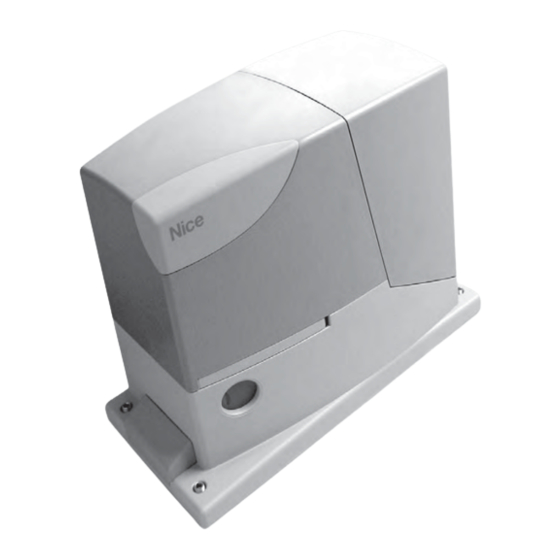
For sliding gates
Road200
Instructions and warnings for the fitter
Istruzioni ed avvertenze per l'installatore
Instructions et recommandations pour l'installateur
Anweisungen und Hinweise für den Installateur
Instrucciones y advertencias para el instalador
Instrukcje i uwagi dla instalatora
Aanwijzingen en aanbevelingen voor de installateur
Advertisement
Table of Contents

Related Manuals for Nice Road200


Summary of Contents for Nice Road200
- Page 1 For sliding gates Road200 Instructions and warnings for the fitter Istruzioni ed avvertenze per l’installatore Instructions et recommandations pour l’installateur Anweisungen und Hinweise für den Installateur Instrucciones y advertencias para el instalador Instrukcje i uwagi dla instalatora Aanwijzingen en aanbevelingen voor de installateur...
-
Page 2: Table Of Contents
Road200 Table of contents: page Warnings Additional information Programming buttons Product description and applications Programming Operating limits 7.2.1 Level one functions (ON-OFF functions) Typical system 7.2.2 Level one programming List of cables (ON-OFF functions) 7.2.3 Level two functions Installation (adjustable parameters) Preliminary checks 7.2.4... -
Page 3: Warnings
“WARNING: MAINTENANCE WORK IN • Any use or operation of ROAD200 which is not explicitly provided for in PROGRESS”. these instructions is not permitted. Improper use may cause damage and personal injury. -
Page 4: List Of Cables
Chapter 8 “Technical Characteristics” provides the data needed to determine whether ROAD200 components are suitable for the intended application. In general, ROAD200 is suitable for the automation of gates featuring leaves up to 5 m wide and weighing up to 200 kg, as shown in Tables 1 and 2. -
Page 5: Installation
3) Installation The installation of ROAD200 must be carried out by qualified personnel in compliance with current legislation, standards and regulations, and the directions provided in this manual. 3.1) Preliminary checks Before proceeding with the installation of ROAD200 you must: •... -
Page 6: Installation Of The Various Devices
If the rack is already present, once the gearmotor has been fastened, use the adjustment dowels as shown in Figure 8 to set the pinion of ROAD200 to the right height, leaving 1÷2 mm of play from the rack. Otherwise, in order to fasten the rack the installer must: 6. -
Page 7: Electrical Connections
1. Remove the protection cover in order to access the electronic figure 13, then block the cable at the first cable block ring using control unit of the ROAD200. The side screw must be removed, the clamp. and the cover lifted upwards. -
Page 8: Description Of The Electrical Connections
7 - 8 Flashing light a NICE “LUCY B” flashing light with a 12V 21W car bulb can be connected to this output. During the manoeuvre the unit flashes at intervals of 0.5 s 4) Final checks and start up... -
Page 9: Recognizing The Length Of The Leaf
1. Press the [PP] button to open the gate. Check that gate open- 5. Check that the fastening of the ROAD200 gearmotor, the rack ing occurs regularly, without any variations in speed. The leaf and the limit switch brackets are solid, stable and suitably resis- must only slowdown and stop when it is between 50 and 30 cm tant, even if the gate accelerates or decelerates sharply. -
Page 10: Memorization Of Radio Transmitters
4.7) Memorization of radio transmitters Each radio transmitter is recognised by the said receiver by means of a “code” which is different from that of any other transmitter. A “mem- orisation” phase must therefore be performed in order to allow the receiver to recognise each single transmitter. Transmitters can be mem- orised in 2 modes: Table 5: Memorization Mode I Mode I: in this mode the function of the transmitter buttons is fixed... -
Page 11: Remote" Memorization
To test ROAD200 proceed as follows: 5. If the dangerous situations caused by the movement of the leaf 1. Ensure that the instructions outlined in this manual and in partic- have been safeguarded by limiting the force of impact, the user ular in chapter 1 "WARNINGS"... -
Page 12: Commissioning
7) Additional information Programming, personalisation and how to look for and deal with faults on the ROAD200 will be dealt with in this chapter. 7.1) Programming buttons The ROAD200 control unit feature three buttons that can be used to command the control unit both during tests and programming. -
Page 13: Programming
If the function is inactive, functioning will be “semi-automatic”. During the normal functioning of ROAD200, LEDs L2 and L3 will either be on or off depending on the state of the function they represent. For example, L3 will be on if the “Automatic Closing” function is active. -
Page 14: Level Two Programming
7.2.4) Level two programming (adjustable parameters) The adjustable parameters are factory set as shown in table 15, with: “ “. However, they can be changed at any time as shown in Table 16. Follow the procedure carefully, as there is a maximum time of 10 seconds between pressing one button and another. If a longer period of time lapses, the procedure will finish automatically and memorize the modifications made up to that stage. -
Page 15: Level Two Programming Example
Wait 10 seconds before leaving the programme to allow the maximum time to lapse. 7.3) Adding or removing devices Devices can be added to or removed from the ROAD200 automa- tion system at any time. In particular, various devices types can be connected to “STOP”... -
Page 16: Photocells
7.3.2) Photocells The ROAD200 control unit is equipped with the “Phototest” function Whereas, if the test has a negative outcome (photocell blinded by the which increases the reliability of the safety devices, making it possible sun, short circuited cable etc), the fault is identified and the manoeu- to achieve "category 2"... -
Page 17: Troubleshooting
No manoeuvre starts and the OK LED does Check that ROAD200 is powered by a 230V mains supply. Check to see if the fuses F1 not flash and F2 are blown; if necessary, identify the reason for the failure and then replace the fuses with others having the same current rating and characteristics. -
Page 18: Signals On The Control Unit
7.7.2) Signals on the control unit On the ROAD200 control unit there is a set of LED each of which can give special indications both during normal operation and in case of malfunctions. Table 21: LED's on the control unit's terminals... -
Page 19: Technical Characteristics
8) Technical characteristics Nice S.p.a., in order to improve its products, reserves the right to modify their technical characteristics at any time without prior notice. In any case, the manufacturer guarantees their functionality and fitness for the intended purposes. All the technical characteristics refer to a room temperature of 20°C (±5°C). - Page 20 Technical characteristics: transmitter: FLO2 transmitter: FLO2R-S transmitter: SM2 Type 2 channel transmitter for radio command Frequency 433.92MHz Coding Digital fixed code with Digital Rolling code Digital Rolling code with 12 Bit code, FLO type with 52 Bit code, FLOR type 64 Bit code, SMILO type buttons Power supply...
-
Page 21: Instructions And Warnings For Users Of Road Gearmotor
This operation movement if people or objects are in the way, guar- has been carefully designed by Nice to make it anteeing safe and reliable activation. However, chil- extremely easy, without any need for tools or physi- dren should not be allowed to play in the vicinity of cal exertion. - Page 22 Are you satisfied? If you wish to install another automation system in your home, call your old installation technician and use Nice products. You will get the services of a specialist and the most advanced products available on the mar- ket, superior performances and maximum system compatibility.
- Page 23 Indirizzo Via Pezza Alta 13, 31046 Z.I. Rustignè, Oderzo (TV) Italia Address Tipo Motoriduttore elettromeccanico “ROAD200” con centrale incorporata Type “ROAD200” electromechanical gearmotor with incorporated control unit Modelli ROAD200 Models Accessori: Accessories Risulta conforme a quanto previsto dalle seguenti direttive comunitarie:...
- Page 24 Aubagne France Fax +34.9.35.88.42.49 Shanghai Tel. +39.06.72.67.17.61 Tel. +33.(0)4.42.62.42.52 info@es.niceforyou.com info@cn.niceforyou.com Fax +39.06.72.67.55.20 Fax +33.(0)4.42.62.42.50 inforoma@niceforyou.com infomarseille@fr.niceforyou.com www.niceforyou.com Nice Gate is the doors and gate automation division of Nice Nice Screen is the rolling shutters and awnings automation division of Nice...
Need help?
Do you have a question about the Road200 and is the answer not in the manual?
Questions and answers