Table of Contents
Advertisement
Quick Links
Download this manual
See also:
User Manual
Advertisement
Table of Contents

Related Manuals for Commell LE-5Q0


Summary of Contents for Commell LE-5Q0
- Page 1 LE-5Q0 Qseven Carrier Board User's Manual Edition 1.3 2017/11/27...
- Page 2 LE-5Q0 User’s Manual Copyright Copyright 2013, all rights reserved. This document is copyrighted and all rights are reserved. The information in this document is subject to change without prior notice to make improvements to the products. This document contains proprietary information and protected by copyright. No part of this document may be reproduced, copied, or translated in any form or any means without prior written permission of the manufacturer.
-
Page 3: Packing List
LE-5Q0 User’s Manual Packing List: Please check the package content before you starting using the board. 1 x LE-5Q0 Motherboard 2 x SATA Cable 1 x COM PORT CABLE (OALSATA3-L / 1040529) (OALES-BKU1NB / 1040086) 1 x USB2.0 Cable 1 x Power Cable... -
Page 4: Table Of Contents
LE-5Q0 User’s Manual Index Chapter 1 <Introduction> ..............4 1.1 <Product Specification> ............... 4 1.2 <Mechanical Drawing> ..............5 1.3 <Block Diagram> ................6 Chapter 2 <Hardware setup> ............7 2.1 <Connector Location and Reference> ........7 2.1.1 <Internal connectors list> ..........8 2.1.2 <External connectors list>... -
Page 5: Chapter 1
LE-5Q0 User’s Manual Chapter 1 <Introduction> 1.1 <Product Specification> System Form Factor 5.25" Qseven Carrier Board QSEVEN Base on Qseven Specification Rev. 2.0 Support 1.8V / 3.3V (Default 1.8V) Expansion 2 x Mini PCIe (card2 support mSATA) (optional), 1 x SIM slot, 1 x SDIO slot Chip 4 x Intel®... -
Page 6: Mechanical Drawing
LE-5Q0 User’s Manual 1.2 <Mechanical Drawing>... -
Page 7: Block Diagram
LE-5Q0 User’s Manual 1.3 <Block Diagram>... -
Page 8: Chapter 2
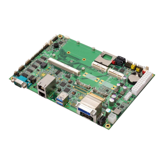
LE-5Q0 User’s Manual Chapter 2 <Hardware setup> 2.1 <Connector Location and Reference> RJ45 - 4/5 RJ45 - 2/3 DP 2/3 USB3.0/2.0 COM1 RJ45 - 1 DP 1 JSPD2 DC_2P JACT2 JACT3 JCSEL2 JVLCD JCSEL1 JSPD3 CN_LVDS1 CN_COM2 DC_IN CN_COM3/4 CN_COM5/6... -
Page 9: Internal Connectors List
LE-5Q0 User’s Manual 2.1.1 <Internal connectors list> Connector Function 230-pin MXM connector (Connector Pinout Description) DC_IN DC 6~27V input connector DC_2P DC 6~27V input connector 24-pin power supply connector CN_LVDS 1/2 20 x 2-pin LVDS connector CN_INV 1/2 5-pin LCD inverter connector... -
Page 10: Jumper Location And Reference
LE-5Q0 User’s Manual 2.2 <Jumper Location and Reference> JCSEL2 JVLCD JCSEL1 JMSATA JRTC JUSBS 2.2.1 <Jumper list> Jumper Function Power mode select JRTC CMOS Normal/Clear Setting JUSBS Mini Card2 USB Setting JVLCD Panel Voltage Setting JMSATA MiniCard2 mSATA Setting JCSEL1... -
Page 11: Clear Cmos And Power On Type Selection
LE-5Q0 User’s Manual 2.3 <Clear CMOS and Power on type selection> JRTC: Clear CMOS data jumper Jumper settings Function Clear CMOS Normal (Default) JAT: AT/ATX mode select jumper Jumper settings Function AT mode ATX mode (Default) JRTC -10-... -
Page 12: I/O Interface
LE-5Q0 User’s Manual 2.4 <I/O interface> 2.4.1 <Ethernet interface> (optional) The board integrates RJ45-2/3/4/5 with Intel I210 Gigabit Ethernet and RJ45-1 with Qseven CPU Module provided , RJ45-2/3/4/5 as the PCI Express bus. The Intel I210 supports triple speed of 10/100/1000 Base-T, with IEEE802.3 compliance and Wake-On-LAN supported. - Page 13 LE-5Q0 User’s Manual 2.4.2.2 <LVDS> The board provides two 40-pin LVDS connector(optional), with two LCD backlight inverter connector (optional)and one jumper for panel voltage setting. Please install LVDS cable before boot up. JVLCD CN_INV CN_LVDS1 JVLCD: LVDS panel power select jumper...
- Page 14 LE-5Q0 User’s Manual CN_LVDS: LVDS 40-pin connector ( Model: HIROSE DF13-40DP-1.25V compatible Signal Signal Set by JVLCD Set by JVLCD A_LVDS_0- B_LVDS_0- A_LVDS_0+ B_LVDS_0+ A_LVDS_1- B_LVDS_1- A_LVDS_1+ B_LVDS_1+ A_LVDS_2- B_LVDS_2- A_LVDS_2+ B_LVDS_2+ A_LVDS_CLK- B_LVDS_3- A_LVDS_CLK+ B_LVDS_3+ A_LVDS_3- B_LVDS_CLK- A_LVDS_3+ B_LVDS_CLK+...
-
Page 15: Audio Interface
LE-5Q0 User’s Manual 2.4.3 <Audio interface> The board integrated onboard audio interface with Realtek ALC262 code, with Intel next generation of audio standard as High Definition Audio, it offers more vivid sound and other advantages than former HD audio compliance. -
Page 16: Usb Interface
LE-5Q0 User’s Manual 2.4.4 <USB interface> USB3.0/2.0 LE-5Q0 integrates 2 x USB3.0 / 2.0, The specifications of USB3.0 are listed below: Interface USB3.0 Transfer Rate Up to 5Gb/s Voltage The specifications of USB2.0 are list: Interface USB2.0 Transfer Rate Up to 480Mb/s... - Page 17 LE-5Q0 User’s Manual CN_USB2-1/2 JUSBS Type: USB2.0, 5VSB Connector: JUSBS Type: 3-pin Power select jumper Description USB7 Mini Card2 USB Default: 2-3 Note: Mini Card2 USB and CN_USB2 (USB7) can’t be enabled simultaneously -16-...
-
Page 18: Serial Port Interface
LE-5Q0 User’s Manual 2.4.5 <Serial Port interface> The board supports five RS232 serial port and one jumper selectable RS232/422/485 serial ports. The jumper JCSEL1 & JCSEL2 can let you configure the communicating modes for CN_COM2. JCSEL2 JCSEL1 COM2 9 10... - Page 19 LE-5Q0 User’s Manual COM1: RS232 DB9 connector Signal Signal Set by JP1 COM2: RS232/422/485 connector Signal Signal DCD/ 422TX-/ 485- RXD/ 422TX+/ 485+ TXD/ 422RX+ DTR/ 422RX- Set by JP2 COM3/4: COM 20-pin header (Pitch 2.54 x 1.27mm) Signal Signal...
- Page 20 LE-5Q0 User’s Manual JP1(COM2), JP2(COM1): pin-9 setting Jumper settings Function RI (Default) Effective patterns of connection: 1-2 / 3-4 / 5-6 Other may cause damage JCSEL1, JCSEL2: For configure COM2 communication mode Function JCSEL2 JCSEL1 RS-422 RS-485 RS-232 (Default) -19-...
-
Page 21: Expansion Slot
LE-5Q0 User’s Manual 2.4.6 <Expansion slot> The board provides two PCIE mini card sockets and a SIM socket. MINI_CARD is the Mini-PCIe slot for half / full size Mini-PCIe cards and Mini Card2 supports mSATA. MINI CARD2 MINI CARD1 JMSATA... - Page 22 LE-5Q0 User’s Manual Connector: SIM (3G MiniPcie Model) Type: 6-pin SIM socket Description Description SIMVCC SIMRST SIMCLK SIMVPP SIMDATA Jumper: JMSATA MINI_CARD Mode JMSATA mSATA 1-2(Note) MINI_CARD2 Default: 2-3 -21-...
-
Page 23: Switch And Indicator
LE-5Q0 User’s Manual 2.4.7 <Switch and indicator> JFRNT JFRNT: Front panel switch and indicator 14-pin header (Pitch 2.54mm) Signal Signal HDD_LED+ Power_LED+ HDD_LED- Reset+ Power_LED- Reset- Speaker+ Power_ON+ Power_ON- Speaker- -22-... -
Page 24: Gpio And Other Interface
LE-5Q0 User’s Manual 2.4.8 <GPIO and Other interface> CN_DIO CN_LPC CPUFAN CN_SMBUS SYSFAN When using GPIO function, please note: As Output: Open-drain, most applications need use an external pull up resistor. (If not may cause damage) As Input: TTL-level. GPIO DC characteristics... - Page 25 LE-5Q0 User’s Manual CN_DIO: GPIO 12-pin header (Pitch 2.00mm) Signal Signal GPIO0 GPIO4 GPIO1 GPIO5 GPIO2 GPIO6 GPIO3 GPIO7 CN_LPC: LPC 12-pin header (Pitch 2.00mm) Signal Signal -LFRAME LAD3 LAD2 LAD1 LAD0 3.3V SERIRQ 3.3VSB CN_LPC support TPM module. CN_SMBUS: SMBus 5-pin header (Pitch 2.54mm)
-
Page 26: Power Supply
LE-5Q0 User’s Manual 2.5 <Power supply> 2.5.1 <Power input> DC_IN The DC_IN supports 9~24V wide voltage input. Note that the DC_IN and ATX do not use at the same time, it will certainly cause damage. DC_IN: ATX12V 4-pin connector Signal... - Page 27 LE-5Q0 User’s Manual 5VSB 3.3V -26-...
-
Page 28: Appendix A
LE-5Q0 User’s Manual Appendix A Appendix A <I/O Port Pin Assignment> A.1 <Serial ATA Port> Connector: SATA1/2 Type: 7-pin wafer connector GND RSATA_TXP1 RSATA_TXN1 GND RSATA_RXN1 RSATA_RXP1 GND A.2 <LAN Port> Connector: RJ45 Description MI0+ MI0- MI1+ MI2+ MI2- MI1-... - Page 29 LE-5Q0 User’s Manual Connector: SDCard Type: 30-pin header for MMC Port Description Description VDDI Ground VCC4 +3.3V VCC3 +3.3V VCC2 +3.3V VCC1 +3.3V VCCQ5 +3.3V VCCQ4 +3.3V VCCQ3 +3.3V VCCQ2 +3.3V VCCQ1 +3.3V SDIO_CLK SDIO_CMD RESET# VSS4 Ground VSS3 Ground...
- Page 30 Taiwan Commate computer Inc. 19F., NO.94, Sec. 1, Xintai 5 Rd., Xizhi Dist., New Taipei Address City 22102, Taiwan. +886-2-26963909 Website www.commell.com.tw info@commell.com.tw (General infomation) E-mail tech@commell.com.tw (Technical Support) Commell is a brand name of Taiwan Commate computer Inc. -29-...
Need help?
Do you have a question about the LE-5Q0 and is the answer not in the manual?
Questions and answers