Table of Contents
Advertisement
Quick Links
Advertisement
Table of Contents

Related Manuals for Commell LE-370


Summary of Contents for Commell LE-370
- Page 1 LE-37O 3.5 inch Motherboard User’s Manual Edition 1.2 2021/05/05...
- Page 2 Trademark All trademarks are the property of their respective holders. Any questions please visit our website at http://www.commell.com.tw...
- Page 3 LE-37O User’s Manual Packing List: Please check the package content before you starting using the board. 1 x Cooler Fan 1 x LE-37O 3.5 inch Miniboard (OHSF-37O / 2181010043) 1 xDC Input Power Cable 1 x SATA Power Cable (OALDC-B / 1040513) (OALSATA15-2PJ / 1040613) 2 x SATA Cable 1 x Dual COM cable...
-
Page 4: Table Of Contents
LE-37O User’s Manual Index Chapter 1 <Introduction>..............4 1.1 <Product Overview>............4 1.2 <Product Specification> ............5 1.3 <Block Diagram>..............6 Chapter 2 <Hardware setup> ............7 2.1 <Connector Location and Reference> ........ 7 2.1.1 <Internal connectors list> ..........8 2.1.2 <External connectors list>.........8 2.2 <Jumper Location and Reference>... -
Page 5: Chapter 1
LE-37O User’s Manual Chapter 1 <Introduction> 1.1 <Product Overview> LE-37O is a 3.5” Motherboard which supports 11th Generation Intel® Core™ U-Series Iris® Xe processors, integrated Graphics, DDR4 memory, Realtek High Definition Audio, Intel Gigabit LAN, USB3.2 Gen2, SATA3 with AHCI function for a system. New feature for Tiger Lake UP3 Tiger Lake UP3 processors are based on the 10nm process node, and offer long-life Iris®... -
Page 6: Product Specification
LE-37O User’s Manual 1.2 <Product Specification> System Intel® Tiger Lake UP3 Processor, FCBGA1449 package Processor 1 x DDR4 SO-DIMM 3200 MHz up to 32GB, Memory Support Non-ECC, unbuffered memory Watchdog Timer Generates a system reset with internal timer for 1min/s ~ 255min/s Real Time Clock Chipset integrated RTC with onboard lithium battery Expansion... -
Page 7: Block Diagram
LE-37O User’s Manual 1.3 <Block Diagram> DDR4 3200 SO-DIMM PTN3460 LVDS HDMI 1 x M.2 KEY M 2280 Tiger Lake UP3 1 x DDR4 2400 SO-DIMM Processor mSATA I219 1 x mini PCIe I225 1 x M.2 (Key E) 2 x SATA 4 x USB3.2 Gen2 ALC262 2 x USB2.0... -
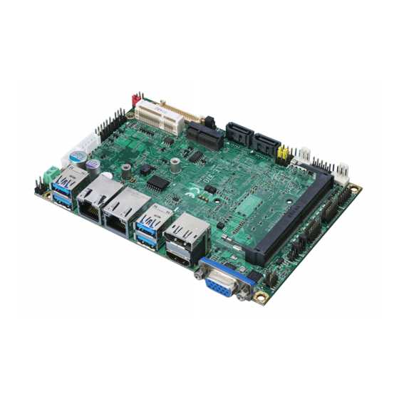
Page 8: Chapter 2
LE-37O User’s Manual Chapter 2 <Hardware setup> 2.1 <Connector Location and Reference> CN_LVDS SATA3-1 CN_USB SATA3-2 CPUFAN SYSFAN JVLCD CN_DIO CN_COM3/4 CN_PS2 JFRNT CN_COM1/2 CN_INV DC_OUT CN_AUDIO CN_BAT CN_SMBus M.2 (KEY M) USB2 I225 I219 USB1 LAN2 LAN1 HDMI... -
Page 9: Internal Connectors List
LE-37O User’s Manual 2.1.1 <Internal connectors list> Connector Function DDR4 260-pin DDR4 SO-DIMM slot SATA3-1/2 7-pin SATA3 connector CN_AUDIO 5 x 2-pin audio pin header CN_DIO 6 x 2-pin General Purpose In/Out pin header CN_LVDS 20 x 2-pin LVDS connector CN_INV 5-pin LCD inverter connector CN_COM1/2... -
Page 10: Jumper Location And Reference
LE-37O User’s Manual 2.2 <Jumper Location and Reference> 2.2.1 <Jumper list> JVLCD JMSATA JRTC Jumper Function Power mode select JRTC CMOS Normal/Clear Setting JVLCD Panel Voltage Setting JMSATA MiniCard mSATA Setting JP1/2 COM1 and CN_COM2 9-pin setting... -
Page 11: Clear Cmos And Power On Type Selection
LE-37O User’s Manual 2.2.2 <Clear CMOS and Power on type selection> JRTC JRTC: Clear CMOS data jumper Jumper settings Function Clear CMOS Normal (Default) JAT: AT/ATX mode select jumper Jumper settings Function AT mode ATX mode (Default) -10-... -
Page 12: Installing The Memory
LE-37O User’s Manual 2.3 <Installing the Memory> LE-37O has 260-pin DDR4 SODIMM support up to 32GB of memory capacity and 1.2 Voltage. The memory frequency supports 3200 MHz. Only Non-ECC memory is supported. In the process, the board must be powered off. 1. -
Page 13: I/O Interface
LE-37O User’s Manual 2.4 <I/O interface> 2.4.1 <Serial ATA interface> Support RAID0, RAID1 SATA 1/2: SATA3 7-pin connector Signal SATA3-2 SATA3-1 2.4.2 <Ethernet interface> The board provides I219-LM and I225-LM Gigabit Ethernet which supports WOL on rear I/O. It supports Intel® AMT 15.0 feature on I219-LM. (Note that the CPU must support vPro technology.) I225-LM I219-LM -12-... -
Page 14: Display Interface
LE-37O User’s Manual 2.4.3 <Display interface> Based on the 11th Gen CPU with built-in Intel® Iris® Xe Graphics, the DisplayPort resolution up to 3840x2160 @ 60Hz or 4096x2304 @ 60Hz, the HDMI up to 4096x2304 @ 24Hz and LVDS up to 1920x1200 @ 60Hz supports single bus or dual bus LVDS signaling with color depths of 18 bits or 24 bits. - Page 15 LE-37O User’s Manual CN_LVDS: LVDS 40-pin connector ( Model: HIROSE DF13-40DP-1.25V compatible Signal Signal Set by JVLCD Set by JVLCD Detect (Active low) A_LVDS_0- B_LVDS_0- A_LVDS_0+ B_LVDS_0+ A_LVDS_1- B_LVDS_1- A_LVDS_1+ B_LVDS_1+ A_LVDS_2- B_LVDS_2- A_LVDS_2+ B_LVDS_2+ A_LVDS_CLK- B_LVDS_3- A_LVDS_CLK+ B_LVDS_3+ A_LVDS_3- B_LVDS_CLK- A_LVDS_3+ B_LVDS_CLK+...
-
Page 16: Serial Port Interface
LE-37O User’s Manual 2.4.4 <Serial Port interface> CN_COM3/4 CN_COM1/2 COM1/2: RS232 20-pin header (Pitch 2.54 x 1.27mm) Signal Signal DCD1 RXD1 TXD1 DTR1 DSR1 RTS1 CTS1 DCD2 RXD2 TXD2 DTR2 DSR2 RTS2 CTS2 -15-... - Page 17 LE-37O User’s Manual COM3/4: RS232/422/485 20-pin header (Pitch 2.54 x 1.27mm) Signal Signal DCD1/ 422TX-/ 485- RXD1/ 422TX+/ 485+ TXD1 DTR1 DSR1/ 422RX+ RTS1 CTS1/ 422RX- DCD2/ 422TX-/ 485- RXD2/ 422TX+/ 485+ TXD2 DTR2 DSR2/ 422RX+ RTS2 CTS2/ 422RX- COM3 & COM4 RS-232/422/485 can set by BIOS.
-
Page 18: Usb Interface
LE-37O User’s Manual 2.4.5 <USB interface> CN_USB USB3.2 Gen2 USB3.2 Gen2 CN_USB: Front panel USB2.0 10-pin header (Pitch 2.54mm) Signal Signal 5VSB 5VSB DATA0- DATA1- DATA0+ DATA1+ -17-... -
Page 19: Audio Interface
LE-37O User’s Manual 2.4.6 <Audio interface> CN_AUDIO CN_USB2-2 CN_AUDIO: Front panel audio 10-pin header (Pitch 1.27mm x 2.54mm) Signal Signal MIC_L MIC_R FP_OUT_R MIC_DETECT SENSE FP_OUT_L FP_OUT_DETECT -18-... -
Page 20: Expansion Slot
LE-37O User’s Manual 2.4.7 <Expansion slot> JMSATA M.2 (KEY M) MINI_CARD has some special design to compatible our mini-PCIe card. MINI_CARD supports mSATA by JMSATA M2 (Key E) with 2x PCI Express x1 support WI-FI and Bluetooth Module M2-M (Key M) with 4x PCIe Gen4, support NVMe SSD. JMSATA: Setting MINI_CARD to support PCIe/mSATA Jumper settings Function... -
Page 21: Front Panel Switch And Indicator
LE-37O User’s Manual 2.4.8 <Front panel switch and indicator> JFRNT JFRNT: Front panel switch and indicator 10-pin header Signal Signal Power_ON- Power_ON+ Speaker- Speaker+ HDD_LED- HDD_LED+ Power_LED- Power_LED+ Reset+ Reset- -20-... -
Page 22: Gpio ,Smbus And Other Interface
LE-37O User’s Manual 2.4.9 <GPIO ,SMBus and Other Interface> SYSFAN CPUFAN CN_DIO CN_PS2 JACT JSPD CN_SMBus -21-... - Page 23 LE-37O User’s Manual When using GPIO function, please note: As Output: Open-drain, most applications need use an external pull up resistor. (If not may cause damage) As Input: TTL-level. GPIO DC characteristics (open drain mode) Parameter UNIT Conditions Input Low Voltage Input High Voltage Output Low Voltage =12mA...
- Page 24 LE-37O User’s Manual CN_SMBus: SMBus 5-pin connector Signal SMBDAT SMBCLK CPUFAN: CPU cooler fan 4-pin connector Signal Sensor Control SYSFAN: System cooler fan 4-pin connector Signal Sensor Control JACT: I219 RJ45 ACT LED 2-pin connector Signal I219 ACT LED- I219 ACT LED+ JSPD: I219 RJ45 SPEED LED 2-pin connector Signal I219 SPEED LED+ (1G) / I219 SPEED LED- (10/100M)
-
Page 25: Power Supply
LE-37O User’s Manual 2.5 <Power supply> 2.5.1 <Power input> DC_IN DC_IN: Terminal block 2-pin power connector Signal Signal 9~35V Power input 2.5.2 <Power output> DC_OUT DC_OUT: SATA power 4-pin connector Signal -24-... -
Page 26: Appendix A
LE-37O User’s Manual Appendix A <Flash BIOS> A.1 <Flash tool> The board is based on Insyde BIOS and can be updated easily by the BIOS auto flash tool. You can download the tool online at the address below: FPT Tool The tool’s file name is “FPT.exe”, it’s the utility that can write the data into the BIOS flash chip and update the BIOS. -
Page 27: Appendix B
EDID Panel type: There are 7 resolutions in LCD Panel Type, if your panel is not in the list, please contact tech@commell.com.tw LVDS Bus: Select Single / Dual channel Panel Color Depth: Select VESA 24 bit / JEIDA 24 bit / VESA and JEIDA 18 bit... -
Page 28: Appendix C
LE-37O User’s Manual Appendix C <Programmable Watch Dog Timer> The watchdog timer makes the system auto-reset while it stops to work for a period. The integrated watchdog timer can be setup as system reset mode by program. You can select Timer setting in the BIOS, after setting the time options, the system will reset according to the period of your selection. - Page 29 LE-37O User’s Manual Program sample Watchdog timer setup as system reset with 5 second of timeout -o 4E 87 ;enter configuration -o 4E 87 -o 4E 07 -o 4F 08 ;select Logical Device -o 4E 30 -o 4F 01 ; activate WDTO# function -o 4E F0 -o 4F 00 ;set “00”...
-
Page 30: Appendix D
LE-37O User’s Manual Appendix D <Hardware Monitor> Find the setting from Advanced-> Motherboard Advanced menu-> Super IO configuration-> Hardware Monitor -29-... -
Page 31: Appendix E
LE-37O User’s Manual Appendix E <Programmable GPIO> The GPIO can be programmed with the MS-DOS debug program using simple IN/OUT commands. GPIO -o 4E 87 ;enter configuration -o 4E 87 -o 4E 07 -o 4F 07 ;select Logical Device -o 4E 30 -o 4F 10 ;activate GPIO function (The board use GPIO4) -o 4E F0... -
Page 32: Appendix F
LE-37O User’s Manual Appendix F <RAID Setting> When use RAID function, it need to enter the BIOS set RAID mode first. Advanced Intel Advanced menu SA Configuration VMD Configuraion 1. Find VMD controller, and set to enable 2. Set “Map this Root port under VMD” to enable. 3. -
Page 33: Contact Information
Taiwan Commate computer Inc. 19F., NO.94, Sec. 1, Xintai 5 Rd., Xizhi Dist., New Taipei Address City 22102, Taiwan. +886-2-26963909 Website www.commell.com.tw info@commell.com.tw (General information) E-mail tech@commell.com.tw (Technical Support) Commell is a brand name of Taiwan Commate computer Inc. -32-...
Need help?
Do you have a question about the LE-370 and is the answer not in the manual?
Questions and answers