
Related Manuals for Technicolor TCA203


Summary of Contents for Technicolor TCA203
- Page 1 Home System Installation Guide Technicolor TCA203 Release Hawaii 5.1 SU1 Drawing number TCA203Install issued 12/19/2012...
- Page 2 Home System Installation Guide Copyright © 2013 iControl Networks All rights reserved. No reproduction in whole or in part without prior written approval. iControl Networks, iControl, and iControl logo design are pending trademarks of iControl Networks. All other trademarks are the property of their respective owners.
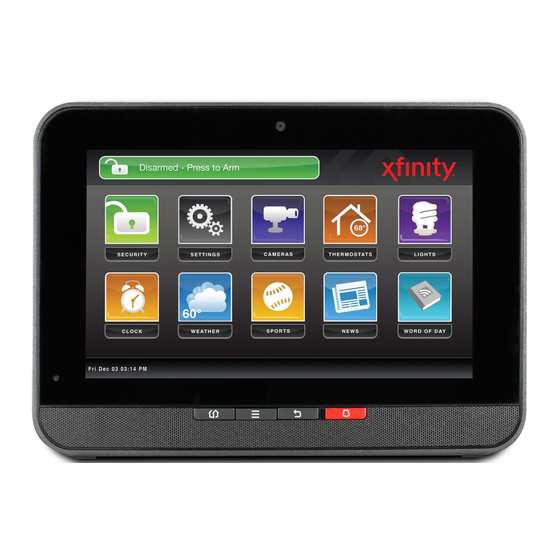
- Page 3 Overview Overview To set up the security system in a customer premises: 1. Complete a Home Security Survey (HSS) for the customer. 2. Ensure the customer premise has access to the Internet. 3. Activate the TouchScreen (see Installing the Security System on page 5).
- Page 4 Home System Installation Guide Installation Tools The following are the tools required to install the security system: Digital multi-meter Double-sided sticky tape Rubbing alcohol with container to dilute with Alternative double-sided sticky tape water Tape measure Paper towels Pocket level Drop cloth for work area Multi-purpose scissors Ladder 6’...
- Page 5 Installing the Security System Installing the Security System Installing the security system in the customer’s home consists of the following general processes. These processes are detailed in the following pages of this section: A. Setting up the Router (page 6) B.
- Page 6 Home System Installation Guide Step A: Setting up the Router 1. Ensure the customer premises has access to the Internet. 2. Reset the home network router. Note: Do this, also, if you are restarting the installation process after having established the connection between the TouchScreen and the router.
- Page 7 Installing the Security System Step B: Installing the Technicolor TouchScreen 1. Remove the TouchScreen from its packaging. 2. Use a P1 Phillips screwdriver to remove the (1) screw from the battery cover of the TouchScreen, and detach the cover. 3. Unwrap the 4.0 volt battery from its packaging and install it in the battery compartment.
- Page 8 Home System Installation Guide 6. Replace the battery cover and the screw. 7. Place the AC power cable through the holes on the sides of the TouchScreen stand. 8. Connect the adapter cable to the back of the TouchScreen.
- Page 9 Installing the Security System 9. Connect the stand to the back of the TouchScreen. Insert the longest peg into the Tamper Switch hole, which is the top right hole on the back of the TouchScreen. Slide the stand downward until the pegs lock in place.
- Page 10 Home System Installation Guide Table 1: AC Power Supply Ratings Rating Value Voltage 100 - 120V Current 0.5A Frequency 60 Hz 13. Remove the center screw from the wall outlet. 14. Plug the TouchScreen’s AC adapter into the TOP plug of the wall outlet, and replace the center screw through the bracket hole.
- Page 11 Installing the Security System Figure 2: Activation: Installation Welcome Screen Note: If the TouchScreen does not display the Installation Welcome screen, you must reset it to factory default (see page 88).
- Page 12 Home System Installation Guide Step C: Ensure Your TouchScreen Configuration Information Is Correct 1. Ensure you have the following information from Customer Care: Activation Code Broadband Server IP Cellular Server IP Cellular APN Deployment to which the TouchScreen, based on CPE ID, is applied in Inventory (only if your system uses deployments) 2.
- Page 13 Installing the Security System Figure 4: Welcome to Product Activation Screen...
- Page 14 Home System Installation Guide Step D: Activating the System Note: To set the language used in the TouchScreen, tap Change Language and choose the preferred language. 1. Tap Next. The Connectivity Setup screen displays the type of Internet routers and cable gateways to which the TouchScreen can connect.
- Page 15 Installing the Security System Figure 6: Connectivity: Connectivity Setup Screen Router/Modem Options The following options are displayed: Wi-Fi - TouchScreen connects to the router/modem wirelessly. If you select this option, follow the procedures described in For Wireless TouchScreen-to-Router Con- nectivity. Ethernet - TouchScreen connects to the router/modem using an Ethernet cable.
- Page 16 Home System Installation Guide Figure 8: Activation: Router Connection Checklist Screen 2. Follow the instructions on the Router Connection Checklist screen. 3. Tap Next. The TouchScreen locates all the available wireless routers in range, and displays their MAC addresses. Figure 9: Activation: Setting Up for Wi-Fi Screen Figure 10: Activation: Router Located Screen 4.
- Page 17 Installing the Security System Figure 11: Activation: Configuring and Securing Router Screen Continue to "Completing Activation" on page 19 For Cabled TouchScreen-to-Router Connectivity Figure 12: Activation: Initial Router Configuration, Ethernet Router-to-TouchScreen 1. Tap Ethernet with Router and then tap Next. The Ethernet Connection Checklist is displayed.
- Page 18 Home System Installation Guide Figure 13: Activation: Ethernet Connection Checklist Screen 2. Follow the instructions on the Ethernet Connection Checklist screen. 3. Tap Next. The Ethernet Adapters screen is displayed. The TouchScreen locates and secures the Ethernet adapter. Figure 14: Activation: Ethernet Adapters Screen 4.
- Page 19 Installing the Security System Figure 15: Activation: Configuring and Securing Router Scree 5. Tap Next and continue to Completing Activation. Completing Activation The Wi-Fi and Cellular Strength screen displays the relative strength of the TouchScreen’s connection to the router/modem and a GPRS/EDGE receiver. Figure 16: Activation: Wi-Fi and Cellular Signal Screen Note: If the router is connected to the TouchScreen by Ethernet, then Wi-Fi is not tested.
- Page 20 Home System Installation Guide Figure 17: Activation: Testing Connectivity Screen 2. Tap Next. The TouchScreen tests its connectivity with the Broadband servers and the Cellular servers, which is used for alarms and alerts when the broadband connection is unavailable. Figure 18: Activation: Testing Connectivity Complete Screen Note: This only tests the TouchScreen’s ability to connect by broadband and cellular.
- Page 21 Installing the Security System Figure 19: Activation: Checking for Firmware Upgrade Screen 5. If an upgrade version is available, tap Upgrade Firmware. The TouchScreen updates the firmware and then reboots. The Activate With Server page is displayed afterward. If an upgrade is not available or after the upgrade is installed, tap Next. The Enter Activation Code keypad is displayed.
- Page 22 Home System Installation Guide Figure 21: Activation: Enter Account Phone Number Screen 7. Enter the Account phone number and tap Next. The system begins the process of activating the TouchScreen with the system servers. Figure 22: Activation: Activating TouchScreen with Server Screen If the Activation fails, check to ensure you have entered the activation code and phone number correctly.
- Page 23 Installing the Security System A screen is displayed offering options to pair the TouchScreen with various security and environmental devices. If the customer requires a panel interface module, the module should be installed first. Otherwise, install the sensors next. Figure 23: Install Zones and Home Devices Screen Note: To test the security connectivity the Internet and cellular servers (after activation): From the Settings app, tap Advanced Settings ®...
- Page 24 Home System Installation Guide Step E: Adding Panel Interface Modules to the Security System The Panel Interface Module (PIM) is a device that allows the TouchScreen to takeover an a previously- installed wireless home security system so that its various elements operate as part of the new overall security system.
- Page 25 Installing the Security System Figure 25: Settings: Locating Panel Interface Boards Screen 2. Tap Next to begin searching for panel interface boards. A PIM can be located only within the first 90 seconds of being powered up. The Vista panel Alphanumeric Keypad should display “Scanning for Network.”...
- Page 26 Home System Installation Guide The TouchScreen searches for zones connected to the panel system. This can take a few minutes. When all the zones are found, an icon for each is displayed on the Configure Panel Interface Sensors screen. Note: When zones connected to the Vista alarm panel are found by the TouchScreen, it automatically configures their functionality (for example, entry/exit, perimeter, etc.) and sensor type (for example, door/window, motion detector, etc.) based on various...
- Page 27 Installing the Security System 8. Otherwise, tap Next to configure the next sensor. Continue until all the sensors have been con- figured. If you need to change the settings of a sensor, see Managing Sensors & Zones on page 94. This action can be performed after wireless sensors are installed as described on Step F: Adding Sensors to the Security System on next page...
- Page 28 Home System Installation Guide Step F: Adding Sensors to the Security System A MAXIMUM of six IP cameras and 47 ZigBee devices are supported for the system. Zig- Bee devices consist of anything that communicates with the TouchScreen over radio frequency, such as door/window sensors, lighting devices, thermostats, panel interface devices, key pads, and key fobs and smoke detectors.
- Page 29 Installing the Security System Figure 27: Sensors and Zones: Locating Wireless Sensors Screen See the installation documentation for each of your sensor device types to prepare them to be added to the TouchScreen and to place them in Search mode. Available sensors meet the following requirements: Defaulted Not currently paired with another TouchScreen device...
- Page 30 Home System Installation Guide 3. Fault each found sensor to pair it to the TouchScreen. For example, for door/window sensors, sep- arate the magnet and reed switch. 4. Determine that all the sensors have been located by the TouchScreen. 5. When all the sensors are found and paired, tap Done. Note: Any located sensors that were not paired are released by the TouchScreen.
- Page 31 Installing the Security System Figure 29: Sensors and Zones: Configure Wireless Sensors Screen 7. Tap each sensor icon to configure it. The Add Sensor/Zone - Modify screen is displayed. Figure 30: Sensors and Zones: Add Sensor/Zone - Modify Screen The details that are available for configuration vary based on the type of sensor being configured.
- Page 32 Home System Installation Guide Figure 31: Sensors and Zones: Add Sensor/Zone - Modify Zone Settings Screen The following table describes the functionality of each zone function.
- Page 33 Installing the Security System Table 2: Security Zone Functions Zone Func- Tamper Faulted Faulted Faulted Faulted Comments tion Armed Unarmed Arm Away Arm Stay Arm Night Entry/Exit Alarms No action Initiates Initiates Alarms For doorways taken entry delay. entry delay. immediately that are used to Alarms if...
- Page 34 Home System Installation Guide Zone Func- Tamper Faulted Faulted Faulted Faulted Comments tion Armed Unarmed Arm Away Arm Stay Arm Night immediate alarm if the system is armed in Away mode. Not armed when the system is in Arm Stay or Arm Night mode.
- Page 35 Installing the Security System Zone Func- Tamper Faulted Faulted Faulted Faulted Comments tion Armed Unarmed Arm Away Arm Stay Arm Night traffic area. 24-Hour Displays trou- No action No Alarm, No Alarm, No Alarm, Default function Inform ble message taken system system system...
- Page 36 Home System Installation Guide Zone Func- Tamper Faulted Faulted Faulted Faulted Comments tion Armed Unarmed Arm Away Arm Stay Arm Night Fire ble message immediately immediately immediately immediately for smoke sen- on Touch- sors Screen Trouble For Armed No action No action No action Alarms...
- Page 37 Installing the Security System Figure 32: Sensors & Zones: Configure Wireless Sensors Screen 10. If all of the sensors have not been configured, the TouchScreen displays the Modify screens for each sensor to allow you to review its details. Modify the details as needed or tap Next to cycle through all the sensors.
- Page 38 Home System Installation Guide Step G: Adding Cameras to the Security System The TouchScreen supports up to six cameras. A camera is added to the security system by using an Ethernet cable to connect it to the security router. After the camera has been added to the security system, remove the cable, and place the camera in the desired location.
- Page 39 Installing the Security System 2. Tap Next. The TouchScreen uploads a binary file multiple times to the system servers to determine the security system’s upload speed. The screen displays the current calculated upload speed. The Upload Speed is used by the system to set the default video quality for the camera. 3.
- Page 40 Home System Installation Guide 4. Perform the steps described on the Hardware Setup screen, including connecting a camera to the TouchScreen’s router with an Ethernet cable and rebooting the camera, and then tap Next. IMPORTANT: The Camera Hardware Setup screen does not apply to iCam installations. If you are installing an iCam, use the following steps to properly add the camera to your TouchScreen.
- Page 41 Installing the Security System The center LED turns on and off as the device boots up. When the LED Left and Center are on and steady, the iCam is reset to factory defaults and ready to be paired to the TouchScreen The Locating Camera screen is displayed.
- Page 42 Home System Installation Guide Figure 36: Camera: Edit New Camera Screen Table 3: Edit New Camera Options Can Be Field Description Modified? Model Model ID for the new camera. The camera manufacturer and model information are sent to the server and logged for inventory reporting and tech support purposes.
- Page 43 Installing the Security System When a camera is assigned to a zone, it takes a series of pictures when an alarm is tripped at that zone. A camera can be assigned to zones for the following types of sensors: door/window sensor, motion detector, glass break detector, smoke detector.
- Page 44 Home System Installation Guide The TouchScreen uploads a file to the system servers to measure the time until it receives an acknowledgement. c. Tap Next to return to the Adjust Camera Video Quality screen. d. Tap the appropriate video quality based on the measured speed, and tap Next. Figure 37: Camera: Adjust Camera Video Quality Screen 10.
- Page 45 Installing the Security System Figure 38: Camera: Camera Wi-Fi Connection Test Screen 11. To have the camera connected to the TouchScreen wirelessly, follow the instructions in the Cam- era Wi-Fi Connection Test screen (including disconnecting the camera from the TouchScreen router and rebooting the camera) and tap Locate Camera.
- Page 46 Home System Installation Guide Tap Next to return to the Install Zones and Home Devices screen is displayed with the Cameras marked done. 16. If you are done configuring devices, tap Next to go to Step M: Testing the Alarm Functionality of the Security System on page Table 5: Troubleshooting the Camera Installation Issue...
- Page 47 Installing the Security System Step H: Adding Lighting Devices to the Security System Lighting devices control whether a light is turned on or off. The system can even manage dimmable lights. This action can be performed after wireless sensors are installed as described on Step F: Adding Sensors to the Security System on page 28.
- Page 48 Home System Installation Guide The lighting devices should be unpaired when they are removed from their packaging. When one is installed in socket, the LED flashes three times every five seconds indicating that it is in Search mode and ready to pair with a TouchScreen. If you have problems pairing a lighting device, do the following to reset it to factory default: Press the On/Off button as you plug the device into the socket.
- Page 49 Installing the Security System 5. Tap Next. The Configure Lighting Devices screen is displayed. 6. Tap a lighting device to configure it as described on page 125. 7. After all the lighting devices are configured, tap Next. The Install Zones and Home Devices screen is displayed with Lights marked done. 8.
- Page 50 Home System Installation Guide Step I: Adding a Thermostat to the Security System This action can be performed after wireless sensors are installed as described on Step F: Adding Sensors to the Security System on page 28. You can skip this step and add a thermostat later as described on page 121.
- Page 51 Installing the Security System The Mate label begins blinking to indicate that the device is in Search mode. When the thermostat device is found, an icon is displayed for that device. 5. Tap Done. The system notes the number of devices that were found and paired. 6.
- Page 52 Home System Installation Guide 9. If you are done configuring devices, tap Next to go to Step M: Testing the Alarm Functionality of the Security System on page...
- Page 53 Installing the Security System Step J: Adding Key Fobs to the Security System A key fob is a mobile tool that lets customers arm and disarm their system with the press of a button. Note: This step can be performed after Activation. IMPORTANT: If you need to update the firmware on any key fob before adding it to the security system, you must reset the key fob to factory defaults before adding it to the...
- Page 54 Home System Installation Guide 3. Default a key fob and place it in Search mode. When a key fob is found,an icon is displayed for it. 4. Press the star button to pair the found key fob. The key fob is paired with the TouchScreen. 5.
- Page 55 Installing the Security System Figure 42: Key Fobs: Configure Wireless Key Fobs Screen 7. Tap each key fob icon to configure the name that is used for it in the TouchScreen and Subscriber Portal. The Edit Keyfob screen is displayed. 2.
- Page 56 Home System Installation Guide 4. Tap the arrow to enable or disable the panic button. 5. Tap Done to return to the Configure Wireless Key Fobs screen 6. After all the key fobs are configured, tap Next. The Install Zones and Home Devices screen is displayed with the Key Pads marked done. 7.
- Page 57 Installing the Security System Step K: Adding Key Pads to the Security System A key pad provides customers a way to enter security codes without using the TouchScreen. Note: This step can be performed after Activation. IMPORTANT: If you need to update the firmware on any key pad before adding it to the security system, you must reset the key pad to factory defaults before adding it to the OpenHome Converge system.
- Page 58 Home System Installation Guide 3. Default a key pad and place it in Search mode. When a key pad is found, an icon is displayed for it. 4. Press the star button to pair the found key pad. The key pad is paired with the TouchScreen and the icon shows a checkmark. 5.
- Page 59 Installing the Security System 7. Tap each key pad icon to configure the name that is used for it in the TouchScreen and Subscriber Portal. A keyboard screen is displayed. 8. Enter a name for the key pad, and tap Done to return to the Configure Wireless Key Pads screen. 9.
- Page 60 Home System Installation Guide 10. If you are done configuring devices, tap Next to go to Step M: Testing the Alarm Functionality of the Security System on page...
- Page 61 Installing the Security System Step L: Adding Sirens to the Security System A MAXIMUM of six IP cameras and 47 ZigBee devices are supported for the system. Zig- Bee devices consist of anything that communicates with the TouchScreen over radio frequency, such as door/window sensors, lighting devices, thermostats, panel interface devices, key pads, and key fobs and smoke detectors.
- Page 62 Home System Installation Guide Figure 43: Locating Sirens Screen See the installation documentation for the sirens to prepare them to be added to the TouchScreen and to place them in Search mode. Available sirens meet the following requirements: Defaulted Not currently paired with another TouchScreen device Currently in Search mode Note: See the siren installation documentation for how to tell if a siren is in Search mode,...
- Page 63 Installing the Security System 3. Fault each found siren to pair it to the TouchScreen. The siren is paired with the TouchScreen and the icon shows a checkmark. 4. Determine that all the sirens have been located by the TouchScreen. 5.
- Page 64 Home System Installation Guide Enter a new label for the siren, if desired. Tap Done to save your changes. The wireless sirens are marked as configured. 8. From this point you can configure any or all of the following devices: Panel Interfaces (see Step E: Adding Panel Inter- Thermostats (see...
- Page 65 Installing the Security System Step M: Testing the Alarm Functionality of the Security System The Test Alarm screen is displayed. Figure 44: Alarm Testing: Test Alarm Screen This step sends a test alarm, through the system servers, to the central monitoring station as though a genuine alarm has been tripped.
- Page 66 Home System Installation Guide Figure 45: Alarm Testing: Verify Signal Sent to Central Screen 3. Call the provided phone number and give the confirmation information to the representative. 4. When you have confirmed that the test alarm was sent successfully, tap Next. The Alarm Test Checklist is displayed.
- Page 67 Installing the Security System Figure 47: Alarm Testing: Alarm Test Checklist Screen 1. Tap Next. The Alarm Test screen is displayed. Figure 48: Alarm Testing: Alarm Test Screen 2. Fault each alarm in turn. The TouchScreen notes that each sensor communicated an event to the TouchScreen and initiated an alarm.
- Page 68 Home System Installation Guide 4. Tap Next. The Review Alarms screen is displayed showing the phone number to contact the central monitoring station to ensure they received all the generated alarms. Figure 49: Alarm Testing: Review Alarms Screen 5. Contact the central monitoring station. 6.
- Page 69 Installing the Security System Step N: Setting and Validating the Security Information The Master code is the keypad code that is required for the customer to access the Settings app and to create and manage other codes. The Set Master Code is displayed. Figure 50: Set Master Code Screen 1.
- Page 70 Home System Installation Guide Figure 51: Validate Account Information: Getting Account Information From Server Screen 3. Tap Next. The Validate Account Information screen is displayed. Figure 52: Validate Account Information: Validate Account Information Screen 4. Ensure that the displayed account information for the customer is accurate—especially the fol- lowing: Phone number that the central monitoring station calls after an alarm Email address that receives an email necessary to perform the Subscriber Portal activation...
- Page 71 Installing the Security System Figure 53: Set Secret Word: Getting Security Secret Word From Server Screen 6. Tap Next. The Set Security Secret Word screen is displayed. Figure 54: Set Secret Word: Set Security Secret Word Screen 7. Show the customer the secret word displayed on the screen. Explain that this is the word that they give to the central monitoring station when it calls to verify whether an alarm is false.
- Page 72 Home System Installation Guide 9. Have the customer type a new secret word and then tap Done. The Set Security Secret Word screen is displayed again. 10. Tap Next. The Activation Complete screen is displayed. Figure 55: Activation Complete Screen 11.
- Page 73 Installing the Security System The TouchScreen reboots.
- Page 74 Home System Installation Guide Step O: Mounting the Sensors 1. Mount the sensors and peripherals as described in the sensor documentation. 2. Test each sensor’s signal strength as described on page 100. IMPORTANT: The minimum distance for the sensors to communicate with the TouchScreen is beyond most practical limits.
- Page 75 Installing the Security System Step P: Configuring the TouchScreen If necessary, perform the following operations: Modify the Entry and Exit delay time periods (see page 85) Modify the Alarm Transmission delay (see page 86) Modify the “swinger shutdown” (see page 87) Reset the TouchScreen to factory defaults (see page 87) Note: This causes the device to require activation again, which in turn requires that the customer’s...
- Page 76 Home System Installation Guide Sensors consist of door/window sensors, motion detectors, glass break detectors, and smoke alarms. Table 6: Sensor Operations Operation Description Modify sen- Change (within limits) the details of a sensor (see page 95). sor details Delete a Remove a sensor from being man- Use these actions in sequence to reset a sensor’s sensor...
- Page 77 Installing the Security System Table 7: Manage Camera Operations Operation Description Modify a camera Change the name identifying each camera in the TouchScreen and the Subscriber Portal. Set or modify the zone to which the camera is assigned. When a camera is assigned to a zone, the camera takes a series of pictures if that zone trips an alarm.
- Page 78 Home System Installation Guide Table 9: Manage Environmental Device Operations Operation Description Delete a lighting Remove a lighting device from your system (see page 128). device Add a lighting Pair a new lighting device to your system (see page 127). device Modify a lighting Change the name identifying each key fob in the TouchScreen and the Subscriber...
- Page 79 Installing the Security System Step Q: Activating the Subscriber Portal 1. With the customer, check the inbox for the email address of the customer’s account (the address displayed on the Validate Account Settings screen). The customer has received an email notification that the security system has been activated. The email provides a temporary username and password to the Subscriber Portal.
- Page 80 Home System Installation Guide Technician Operations Customers can use the Settings menu to access a variety of operations to configure and maintain their security system as described in the iControl TouchScreen User's Guide. When an installer accesses the Settings menu with an Installer keypad code, he has access to operations available to the customer as well as other operations unavailable to a customer.
- Page 81 Technician Operations The Installer Settings menu is displayed. The following Installer operations are available from the Installer Settings menu: Configure the Entry/Exit Manage the camera (page 112) delay periods (page 85) Manage the lighting devices (page 125) Configure the Alarm Trans- Manage thermostats (page 121) mission delay (page 86) Manage key fobs (page 129)
- Page 82 Home System Installation Guide Figure 56: Settings: Alarm Test Options Screen 3. To have your test alarms reported to central monitoring, tap Disabled. The button changes to Enabled. Your test alarms are sent to the central monitoring station. Note: If the Enabled button is already displayed, tap Enabled to choose to have your test alarms NOT sent to central monitoring.
- Page 83 Technician Operations When the security zones are ready for testing, “Ready to Arm” is displayed under the Arm button. 6. Tap Arm. Your security system is armed in the special Test mode. The Exit Delay is only ten seconds long. Motion sensors are turned off (not tripping alarms but recording events) until an Entry/Exit security zone is faulted.
- Page 84 Home System Installation Guide Figure 59: Settings: Alarm Test Screen 9. Fault each additional alarm as described in the following table and ensure that it is marked as alarm. Table 10: Sensor Testing Operations Sensor Testing Process Door/Window Open and close the door or window. Motion Detec- Avoid the motion detector’s view for three minutes after arming the system, then walk in front of it.
- Page 85 Technician Operations Figure 60: Settings: Review Alarm Screen 12. Review the zone event history. 13. Ensure you have received any configured alerts via email or SMS. 14. If you enabled Send Test Alarm Messages, contact the central monitoring station's Test number to ensure that they received all the generated alarms.
- Page 86 Home System Installation Guide To configure the Entry/Exit Delay periods: 1. From the Installer Settings menu, tap Security >Entry And Exit Delay. The Entry and Exit Delay screen is displayed. Figure 61: Settings: Entry and Exit Delay Screen 2. Tap the right and left-pointing arrows to increase and decrease the Entry Delay and Exit Delay peri- ods by increments of five seconds.
- Page 87 Technician Operations To configure the Alarm Transmission Delay period: 1. From the Installer Settings menu, tap Security >Alarm Transmission Delay. The Alarm Transmission Delay screen is displayed. Figure 62: Settings: Alarm Transmission Delay Screen 2. Tap the right and left-pointing arrows to increase and decrease the Alarm Transmission Delay period.
- Page 88 Home System Installation Guide To configure the swinger shutdown: 1. From the Installer Settings menu, tap Security ® Swinger Shutdown. The Swinger Shutdown Settings screen is displayed. Figure 63: Settings: Swinger Shutdown Settings 2. Tap the right and left-pointing arrows to increase and decrease the number of swinger shutdown trips (Maximum Trips).
- Page 89 Technician Operations The Reset Touchscreen to Factory Defaults screen is displayed. 3. Tap Reset to Factory Defaults. The Keypad screen is displayed. 4. Enter the Installer keypad code. The Keyboard screen is displayed.
- Page 90 Home System Installation Guide 5. Enter the PREMISE PASSPHRASE for the current account. The device resets and the Installation screen is displayed. To activate the system again: 1. Contact Customer Care to have the customer’s account reset. 2. Follow the steps starting on page to activate the system again.
Need help?
Do you have a question about the TCA203 and is the answer not in the manual?
Questions and answers