Table of Contents
Advertisement
Quick Links
Advertisement
Table of Contents

Related Manuals for FLIR X6570sc series


Summary of Contents for FLIR X6570sc series
- Page 1 User’s manual FLIR X6570sc series...
- Page 3 User’s manual FLIR X6570sc series #T810204; r. AA/43079/43091; en-US...
-
Page 5: Table Of Contents
LCD screen..............15 6.3.2 Lens................17 Setting the camera parameters ..........19 6.4.1 Connection to the computer..........19 6.4.2 Connection to FLIR ResearchIR Max........ 19 6.4.3 Image size adjustment........... 20 6.4.4 Measurement configuration ..........21 6.4.5 Temperature range adjustment........22 6.4.6... - Page 6 Table of contents 7.1.1 Removing an optical filter holder ........27 7.1.2 Installing an optical filter holder........27 7.1.3 Filter holder identification ..........28 7.1.4 Creating a custom filter holder......... 28 7.1.5 Installing two filters in the filter holder........ 29 7.1.6 Adding a custom filter parameter into the camera ....
- Page 7 17.1 Introduction ................73 17.2 Definition—what is calibration? ..........73 17.3 Camera calibration at FLIR Systems ........... 73 17.4 The differences between a calibration performed by a user and that performed directly at FLIR Systems........74 17.5 Calibration, verification and adjustment........74 17.6...
-
Page 9: Disclaimers
Products which are not manufactured by FLIR Systems but included in systems deliv- ered by FLIR Systems to the original purchaser, carry the warranty, if any, of the particu- lar supplier only. FLIR Systems has no responsibility whatsoever for such products. -
Page 10: Government Regulations
1.5 Copyright © 2016, FLIR Systems, Inc. All rights reserved worldwide. No parts of the software in- cluding source code may be reproduced, transmitted, transcribed or translated into any language or computer language in any form or by any means, electronic, magnetic, opti- cal, manual or otherwise, without the prior written permission of FLIR Systems. -
Page 11: Fonts (Dejavu)
Disclaimers 1.8.3 Fonts (DejaVu) http://dejavu-fonts.org/wiki/License (Retrieved May 27, 2015) #T810204; r. AA/43079/43091; en-US... -
Page 12: Safety Information
Safety information For best results and user safety, the following warnings and precautions should be fol- lowed when handling and operating the camera. • Do not open the camera body for any reason. Disassembly of the camera (including removal of the cover) can cause permanent damage and will void the warranty. •... -
Page 13: Notice To User
3.7 Important note about this manual FLIR Systems issues generic manuals that cover several cameras within a model line. #T810204; r. AA/43079/43091; en-US... -
Page 14: Note About Authoritative Versions
Notice to user This means that this manual may contain descriptions and explanations that do not apply to your particular camera model. 3.8 Note about authoritative versions The authoritative version of this publication is English. In the event of divergences due to translation errors, the English text has precedence. -
Page 15: Customer Help
• The communication protocol, or method, between the camera and your device (for ex- ample, SD card reader, HDMI, Ethernet, USB, or FireWire) • Device type (PC/Mac/iPhone/iPad/Android device, etc.) • Version of any programs from FLIR Systems • Full name, publication number, and revision number of the manual 4.3 Downloads... - Page 16 Customer help • Firmware updates for your infrared camera. • Program updates for your PC/Mac software. • Freeware and evaluation versions of PC/Mac software. • User documentation for current, obsolete, and historical products. • Mechanical drawings (in *.dxf and *.pdf format). •...
-
Page 17: Introduction
Introduction 5.1 Camera system components The FLIR X6570sc infrared camera and its accessories are delivered in a transport case that typically contains the items below. • FLIR X6570sc camera with removable LCD touchscreen. • Portfolio that includes important information on the camera: ◦... -
Page 18: View From The Front-M80 Mount
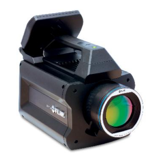
Introduction 5.2.1 View from the front—M80 mount Figure 5.1 View from the front—M80 mount. 1. Wi-Fi antenna. 2. Global status LED. 3. Lens M80 interface. 5.2.2 View from the rear Figure 5.2 View from the rear. 1. Removable touch screen LCD. 2. -
Page 19: Back Panel
Introduction 5.2.3 Back panel Figure 5.3 Camera back panel description. 1. Power button. 2. Status LED. 3. Infrared remote sensor. 4. Sync In. 5. Sync Out. 6. Power In. 7. Lock-in In. 8. General-purpose IO. 9. Trigger In. 10. Auxiliary port. 11. -
Page 20: Key Features
5.3 Key features • Fast frame rate The FLIR X6570sc series has an adjustable frame rate. Windowing allows a subset of the total image to be selectively read out with a user-adjustable window size. The sub-sample windows can be arbitrarily chosen and are easily defined. - Page 21 Introduction FLIR X6570sc camera when the camera needs to be installed in a hard to reach loca- tion. Simply position the camera and control it at a distance. • Wi-Fi The camera includes a Wi-Fi interface, which enables it to be controlled by a smart phone (iPhone) or a tablet (iPad).
-
Page 22: Installing The Camera
Installing the camera 6.1 Mounting the camera The camera can be operated installed either on a workbench or mounted on a tripod or custom mount. A standard photo mount (¼-20 UNC) or 3 × M5 mounting holes on the camera base as well as 3 × M5 mounting holes on the left side of the camera are provided. -
Page 23: Power Button
Use of the LCD screen is helpful during this procedure. 6.3.1 LCD screen The FLIR X6570sc includes a detachable touch screen LCD that provides instant ther- mal image feedback. The LCD screen also provides camera information, adjustment controls, and ResearchIR Max acquisition control. - Page 24 Installing the camera Figure 6.1 LCD touch screen. 1. Image statistics. 2. Add spot tool: center, cold, or hot. 3. Camera information. 4. Measurement configuration. 5. Start acquisition in ResearchIR Max. 6. Auto-exposure. 7. Change the color palette. 6.3.1.1 Detaching the touch screen LCD The LCD screen can be detached from the camera and used remotely when the camera is mounted in a hard to reach location.
-
Page 25: Lens
6.4.8 Advanced camera controls, page 24). 6.3.2 Lens A large range of lenses is available for the FLIR X6570sc. The lenses feature a professio- nal M80 mount. Note FLIR is continuously extending its range of available optics. Contact your FLIR sales representative for more information on newly available optics. - Page 26 • Using extension rings requires a good understanding of their radiometric effects and the resulting measurement errors. The Infrared Training Center (ITC) offers courses and training. For more information on any training you require, contact your FLIR sales representative or ITC at www.infraredtraining.com.
-
Page 27: Setting The Camera Parameters
6.4.1.2 Connection through the GigE interface The FLIR X6570sc features a GigE connection. The GigE interface can be used for im- age acquisition and/or camera control. The GigE interface is GigE Vision compliant. -
Page 28: Image Size Adjustment
6.4.3 Image size adjustment 6.4.3.1 General The FLIR X6570sc can be set up to use only part of the detector. This allows the camera can be operated at higher frame rates. The selection is done through the upper part of the camera control panel. -
Page 29: Measurement Configuration
A measurement configuration is a combination of optical setup (lens and spectral filter), integration mode setting, and Camera Link setting. The measurement configurations available in the camera are displayed in the FLIR Re- searchIR Max interface. Each configuration is described with minimum and maximum calibrated temperatures, the lens and filter type, the integration mode (ITR or IWR), and the Camera Link setting (Base/Medium). -
Page 30: Temperature Range Adjustment
39 for more information on superframing. 4. The FLIR X6570sc features an automatic exposure control that automatically selects the best integration time for the current thermal scene. Refer to section 8.2.2 Auto-ex- posure, page 35 for more information on auto-exposure. -
Page 31: Frame Frequency
Installing the camera 5.1. Select the temperature range to measure. 5.2. The wizard automatically calculates the best integration times to cover the de- sired temperature range. Click on the Finish button to set up the camera accordingly. 6. Apply the temperature range configuration to the camera. 7. -
Page 32: Advanced Camera Controls
Installing the camera Synchronization parameters are set through the ResearchIR Max user interface: 1. Activate/deactivate external synchronization. Select the active edge and input impedance. 2. Based on the camera configuration (e.g., the window size, integration time, or inte- gration mode), the maximum allowable Sync In frequency is displayed. 3. -
Page 33: Extended Camera Information
6.4.1.1 Connection through the Cam- era Link interface, page 19. The streaming mode should always be set to Base for the FLIR X6570sc. Auto measurement configuration selection When this option is checked, the camera auto- matically searches the measurement configura- tion corresponding to the exact optical path (filter + lens) and detector configuration. - Page 34 Installing the camera Temperature Probes The camera is equipped with various temperature probes that are used for improving measurement accuracy or for camera diagnostics. Click the refresh button to update the temperature values. Miscellaneous This section lists the firmware version information, the model, and the serial number of the camera Image Statistics The image statistics as measured by the camera...
-
Page 35: Operation
Operation 7.1 Filter wheel The FLIR X6570sc includes a four-slot filter wheel. Each slot can hold a 1 in. (2.5 cm) di- ameter filter with a thickness of up to 2.5 mm. An identification system has been imple- mented so that the camera recognizes the inserted slot and automatically adjusts the measurement configuration. -
Page 36: Filter Holder Identification
7.1.3 Filter holder identification Each filter holder is identified by a combination of magnets glued onto the filter holder. FLIR provides standard filter configurations with corresponding identification numbers (IDs). At start-up, the camera scans the filter wheel and identifies the inserted holders. If equipped with a lens with a bayonet mount, the camera also adjusts the measurement configuration in accordance with the identified filter holders. -
Page 37: Installing Two Filters In The Filter Holder
Operation 4. Place your filter in the holder. Take care to ensure correct filter orientation, to avoid er- rors in the radiometric measurement. Contact your filter provider for this information. 5. Gently insert the threaded filter ring, and tighten it using the filter tool. Take great care not to damage the filter with the tool. -
Page 38: Adding A Custom Filter Parameter Into The Camera
Operation 3. Place the centering ring into the holder. 4. Clean the visible filter surface. 5. Place the filter spacer on top of the first filter. 6. Place the second filter into the holder. Make sure it seats correctly on top of the filter spacer and is centered with the centering ring. -
Page 39: Filter Definition File Description
Slot.ini file and must start with the capital letter “F.” [reference] F1201 #name max 20 char The user-friendly name that is displayed in the Re- searchIR Max user interface. FLIR uses the fol- [name] lowing naming convention, but it can be freely NA_4094_4388_60% modified. -
Page 40: Camera Configuration File Management
Operation #cuton in nm Filter cut-in (in nm) [cuton] If unknown, enter “0.” 4094 #cutoff in nm Filter cut-off (in nm) [cutoff] If unknown, enter “0.” 4388 #transmission in % Average filter transmission (in %) [transmission] If unknown, enter “0.” #tolerance in % Filter spectral tolerance [tolerance]... -
Page 41: Camera Web
ResearchIR Max. 7.4 Infrared remote 7.4.1 General The FLIR X6570sc can be controlled with the provided infrared remote or any XLR cam- era remote control using the Nikon protocol. The actions available are as follows: • Start acquisition in ResearchIR Max. -
Page 42: Radiometric Measurement
A CNUC correction is valid for a specific optical configuration comprising a lens and spectral filters combination. CNUC corrections are generated by FLIR service offices where advanced calibration benches are available. Contact your FLIR representative for CNUC correction on new spectral filters or infrared lenses. -
Page 43: One-Point Correction (Offset Correction)
Note ±1°C or ±1% accuracy is standard for the FLIR X6570sc, unless explicitly speci- fied otherwise. Typically, calibration on custom spectral filters or custom optical configu- rations have higher-accuracy tolerances. -
Page 44: Bad Pixel Replacement
Radiometric measurement Note • The auto-exposure process looks for the best integration time for the actual thermal scene. It may be the case that this preferred integration time is not achievable be- cause it is limited by the camera’s frame rate. In this case, the auto-exposure process is stopped, and the preferred integration is not applied. -
Page 45: The Itr Process
All timings for the frame generation process are based on a 20 MHz clock, yielding a res- olution of 50 ns. The minimum integration time for the FLIR X6570sc is 10 µs. 8.5.2.1 Maximum achievable frame rate in ITR—base mode Table 8.1 Maximum frame rate (in Hz) versus image size (detector mode: ITR/base/integration time = 10... - Page 46 Radiometric measurement Table 8.2 Maximum frame rate (in Hz) versus image size (detector mode: ITR/base/integration time = 500 µs) Number of points Num- ber of lines 1022 1027 1101 1005 1123 1193 1035 1128 1239 1303 1008 1066 1130 1203 1286 1381 1434...
-
Page 47: Procedure
Figure 5.3 Camera back panel description., page 11) and a Sync Out connector (5 in Fig- ure 5.3 Camera back panel description., page 11). The FLIR X6570sc makes use of frame synchronizations to control the generation of im- age data. The generation of a frame consists of two phases: integration and data read- out. -
Page 48: Sync In
If the external synchronization rate is too fast, the camera will ignore syn- chronizations that occur before the camera is ready. • If the frame rate is too low, the image quality may deteriorate. Contact your FLIR rep- resentative if you have questions about low frame rates for your specific camera model. -
Page 49: Sync Out
Radiometric measurement 8.7.1.3 Chronogram Name Value Notes Jitter 12.5 ns 1 pixel clock (80 M) Fixed delay 690 ns Propagation through the back panel card + propagation from the FPGA to the detector Manual delay – Set by the user Integration Time –... -
Page 50: Trigger In
Radiometric measurement Name Value Impedance High impedance Minimum pulse width 300 ns Protection Voltage peaks (500 V/<1 ns) Overvoltage (15 V) Reversed polarity Connector Coaxial BNC jack 1. Example: If the detector is working at 100 in full frame, then the maximum frequency will be 100. 8.7.2.3 LED description LED status Description... -
Page 51: Characteristics
The FLIR X6570sc features a lock-in signal input BNC connector on the back panel of the camera (7 in Figure 5.3 Camera back panel description., page 11). -
Page 52: Irig-B
Coaxial BNC jack 8.10 IRIG-B The FLIR X6570sc features an IRIG-B input BNC connector (colored blue) on the back panel of the camera (8 in Figure 5.3 Camera back panel description., page 11). The value of the signal is digitalized during the integration of the infrared image and em- bedded within it. -
Page 53: Interfaces
9.1 Wi-Fi connection 9.1.1 General It is possible to connect to the FLIR X6570sc using the camera’s integrated Wi-Fi and a peer-to-peer (ad hoc) WLAN network. This connection allows control of image acquisi- tion in ResearchIR Max from the camera (same functions as on the LCD screen). -
Page 54: Usb Connection
Interfaces 4. Connect to http://192.168.64.1/ 9.2 USB connection 9.2.1 General The camera features a USB connector that is used to access to the camera’s internal file system. Once connected, the connection allows: • Access to the camera memory, to upload configuration and CNUC files. •... -
Page 55: Usb Driver Installation
Interfaces The USB connection requires a FLIR USB driver on the camera and also on the com- puter. Depending on the camera, there are two scenarios: 1. The camera has a newer FLIR USB driver When the FLIR ReseachIR Max software is installed on the computer, a valid FLIR USB driver is automatically installed on the computer. - Page 56 2. Connect the camera to the computer with the USB cable. 3. Open Control Panel > Device Manager. 4. Under Network adapters, find the device named FLIR Platinum USB. 5. Right-click and select Update Driver Software. #T810204; r. AA/43079/43091; en-US...
- Page 57 Interfaces 6. Select Browse my computer for driver software. 7. Select Let me pick from a list of device on my computer. 8. Click the Have Disk… button. #T810204; r. AA/43079/43091; en-US...
- Page 58 Interfaces 9. Browse and select the file FLIR X8400sc - X6500sc – USB.inf file. 10. Select Driver X8400sc – X6500sc – USB, and click the Next button. 11. Click Install this driver software anyway. The driver is now installing. If the installation does not progress correctly, try unplugging the USB cable from the computer.
-
Page 59: Configuration Of The Network Interface
Interfaces 13. Device Manager now shows the new device FLIR X8400sc – X6500sc. 14. Configure the network interface by following the procedure in section 9.2.3 Configu- ration of the network interface, page 51. 9.2.3 Configuration of the network interface 9.2.3.1 Procedure 1. - Page 60 Interfaces 2. Right-click on the FLIR X8400sc – X6500sc connection and click Properties, then se- lect Internet Protocol V4 and click the Properties button. #T810204; r. AA/43079/43091; en-US...
-
Page 61: Accessing The Camera Files With Windows Explorer
• Use Windows Explorer to access camera files such as CNUC, lens, and filter ID descriptors. • Use ResNet to access the camera registry. ResNet is an internal tool. Contact your FLIR service department for more information. 9.2.4 Accessing the camera files with Windows Explorer 9.2.4.1 General Note •... - Page 62 Interfaces 2. Set the LAN Manager authentication level to “Send LM & NTLM responses.” #T810204; r. AA/43079/43091; en-US...
-
Page 63: Mechanical Drawings
Mechanical drawings [See next page] #T810204; r. AA/43079/43091; en-US... -
Page 65: Technical Data
Technical data 11.1 Note about technical data FLIR Systems reserves the right to change specifications at any time without prior notice. Please check http://support.flir.com for latest changes. 11.2 Note about authoritative versions The authoritative version of this publication is English. In the event of divergences due to translation errors, the English text has precedence. -
Page 66: Flir X6570Sc
Operational 2g, IEC 68-2-26 Radiometry Spectral band Long-wave infrared 7.7–9.3 µm Spectral range Thermal sensitivity/NETD <25 mK (20 mK typical) CNUC/Hypercal 1. Some cameras also have a minimum frame rate, unspecified. Contact your FLIR representative for more information. #T810204; r. AA/43079/43091; en-US... - Page 67 Technical data Radiometry Temperature measurement accuracy ±1°C (1.8°F) or ±1% Maximum temperature without filter 150°C (302°F) Filter wheel 4 slots for 1 in. filter up to 2.5 mm thick Filter holding Bayonet Timings and signals Optical interface SYNC IN TTL, singled ended, BNC >300 ns pulse width SYNC IN Jitter 12.5 ns SYNC IN active edge...
-
Page 68: Maintenance And Service
Maintenance and service 12.1 Cleaning the camera 12.1.1 Camera housing, cables, and other items 12.1.1.1 Liquids Use one of these liquids: • Warm water • A weak detergent solution 12.1.1.2 Equipment A soft cloth 12.1.1.3 Procedure Follow this procedure: 1. Soak the cloth in the liquid. 2. -
Page 69: Cooler Maintenance
12.2.2 Signs to watch for The FLIR Systems microcooler is equipped with a closed-loop speed regulator, which adjusts the cooler motor speed to regulate the detector temperature. Typically, the cooler runs at maximum speed for 7–10 minutes (depending on model), and then slows to about 40% of maximum speed. -
Page 70: Quality
The quality management system under which this product is developed and manufac- tured has been certified in accordance with the ISO 9001 standard. FLIR Systems is committed to a policy of continuous development; therefore, we reserve the right to make changes and improvements to the product described in this manual without prior notice. -
Page 71: About Flir Systems
• Prox Dynamics (2016) Figure 14.1 Patent documents from the early 1960s FLIR Systems has three manufacturing plants in the United States (Portland, OR, Boston, MA, Santa Barbara, CA) and one in Sweden (Stockholm). Since 2007 there is also a manufacturing plant in Tallinn, Estonia. -
Page 72: More Than Just An Infrared Camera
14.1 More than just an infrared camera At FLIR Systems we recognize that our job is to go beyond just producing the best infra- red camera systems. We are committed to enabling all users of our infrared camera sys- tems to work more productively by providing them with the most powerful camera–... -
Page 73: Supporting Our Customers
About FLIR Systems 14.3 Supporting our customers FLIR Systems operates a worldwide service network to keep your camera running at all times. If you discover a problem with your camera, local service centers have all the equipment and expertise to solve it within the shortest possible time. Therefore, there is no need to send your camera to the other side of the world or to talk to someone who does not speak your language. -
Page 74: Terms, Laws, And Definitions
Terms, laws, and definitions Term Definition Absorption and emission The capacity or ability of an object to absorb incident radi- ated energy is always the same as the capacity to emit its own energy as radiation Apparent temperature uncompensated reading from an infrared instrument, con- taining all radiation incident on the instrument, regardless of its sources Color palette... - Page 75 Terms, laws, and definitions Term Definition Radiative heat transfer Heat transfer by the emission and absorption of thermal radiation Reflected apparent temperature apparent temperature of the environment that is reflected by the target into the IR camera Spatial resolution ability of an IR camera to resolve small objects or details Temperature measure of the average kinetic energy of the molecules and atoms that make up the substance...
-
Page 76: Thermographic Measurement Techniques
Thermographic measurement techniques 16.1 Introduction An infrared camera measures and images the emitted infrared radiation from an object. The fact that radiation is a function of object surface temperature makes it possible for the camera to calculate and display this temperature. However, the radiation measured by the camera does not only depend on the tempera- ture of the object but is also a function of the emissivity. - Page 77 Thermographic measurement techniques 16.2.1.1.1 Method 1: Direct method Follow this procedure: 1. Look for possible reflection sources, considering that the incident angle = reflection angle (a = b). Figure 16.1 1 = Reflection source 2. If the reflection source is a spot source, modify the source by obstructing it using a piece if cardboard.
- Page 78 Thermographic measurement techniques 3. Measure the radiation intensity (= apparent temperature) from the reflection source using the following settings: • Emissivity: 1.0 • D You can measure the radiation intensity using one of the following two methods: Figure 16.3 1 = Reflection source Figure 16.4 1 = Reflection source You can not use a thermocouple to measure reflected apparent temperature, because a thermocouple measures temperature, but apparent temperatrure is radiation intensity.
- Page 79 Thermographic measurement techniques 5. Measure the apparent temperature of the aluminum foil and write it down. The foil is considered a perfect reflector, so its apparent temperature equals the reflected appa- rent temperature from the surroundings. Figure 16.5 Measuring the apparent temperature of the aluminum foil. 16.2.1.2 Step 2: Determining the emissivity Follow this procedure: 1.
-
Page 80: Reflected Apparent Temperature
50%. 16.6 Other parameters In addition, some cameras and analysis programs from FLIR Systems allow you to com- pensate for the following parameters: • Atmospheric temperature – i.e. the temperature of the atmosphere between the cam- era and the target •... -
Page 81: About Calibration
17.3 Camera calibration at FLIR Systems Without calibration, an infrared camera would not be able to measure either radiance or temperature. At FLIR Systems, the calibration of uncooled microbolometer cameras with a measurement capability is carried out during both production and service. Cooled cam- eras with photon detectors are often calibrated by the user with special software. -
Page 82: The Differences Between A Calibration Performed By A User And That Performed Directly At Flir Systems
The calibration information, no matter if the calibration is done by FLIR Systems or the user, is stored in calibration curves, which are expressed by mathematical functions. As... -
Page 83: Non-Uniformity Correction
About calibration Calibration is also a prerequisite for adjustment, which is the set of operations carried out on a measuring system such that the system provides prescribed indications corre- sponding to given values of quantities to be measured, typically obtained from measure- ment standards. -
Page 84: History Of Infrared Technology
History of infrared technology Before the year 1800, the existence of the infrared portion of the electromagnetic spec- trum wasn't even suspected. The original significance of the infrared spectrum, or simply ‘the infrared’ as it is often called, as a form of heat radiation is perhaps less obvious to- day than it was at the time of its discovery by Herschel in 1800. - Page 85 History of infrared technology When Herschel revealed his discovery, he referred to this new portion of the electromag- netic spectrum as the ‘thermometrical spectrum’. The radiation itself he sometimes re- ferred to as ‘dark heat’, or simply ‘the invisible rays’. Ironically, and contrary to popular opinion, it wasn't Herschel who originated the term ‘infrared’.
- Page 86 History of infrared technology Figure 18.4 Samuel P. Langley (1834–1906) The improvement of infrared-detector sensitivity progressed slowly. Another major break- through, made by Langley in 1880, was the invention of the bolometer. This consisted of a thin blackened strip of platinum connected in one arm of a Wheatstone bridge circuit upon which the infrared radiation was focused and to which a sensitive galvanometer re- sponded.
-
Page 87: Theory Of Thermography
Theory of thermography 19.1 Introduction The subjects of infrared radiation and the related technique of thermography are still new to many who will use an infrared camera. In this section the theory behind thermography will be given. 19.2 The electromagnetic spectrum The electromagnetic spectrum is divided arbitrarily into a number of wavelength regions, called bands, distinguished by the methods used to produce and detect the radiation. -
Page 88: Planck's Law
Such cavity radiators are commonly used as sources of radiation in tempera- ture reference standards in the laboratory for calibrating thermographic instruments, such as a FLIR Systems camera for example. If the temperature of blackbody radiation increases to more than 525°C (977°F), the source begins to be visible so that it appears to the eye no longer black. -
Page 89: Wien's Displacement Law
Theory of thermography where: Blackbody spectral radiant emittance at wavelength λ. λb Velocity of light = 3 × 10 Planck’s constant = 6.6 × 10 Joule sec. Boltzmann’s constant = 1.4 × 10 Joule/K. Absolute temperature (K) of a blackbody. λ... -
Page 90: Stefan-Boltzmann's Law
Theory of thermography Figure 19.5 Wilhelm Wien (1864–1928) The sun (approx. 6 000 K) emits yellow light, peaking at about 0.5 μm in the middle of the visible light spectrum. At room temperature (300 K) the peak of radiant emittance lies at 9.7 μm, in the far infra- red, while at the temperature of liquid nitrogen (77 K) the maximum of the almost insignif- icant amount of radiant emittance occurs at 38 μm, in the extreme infrared wavelengths. -
Page 91: Non-Blackbody Emitters
Theory of thermography Figure 19.7 Josef Stefan (1835–1893), and Ludwig Boltzmann (1844–1906) Using the Stefan-Boltzmann formula to calculate the power radiated by the human body, at a temperature of 300 K and an external surface area of approx. 2 m , we obtain 1 kW. - Page 92 Theory of thermography • A selective radiator, for which ε varies with wavelength According to Kirchhoff’s law, for any material the spectral emissivity and spectral absorp- tance of a body are equal at any specified temperature and wavelength. That is: From this we obtain, for an opaque material (since α...
-
Page 93: Infrared Semi-Transparent Materials
Theory of thermography 19.4 Infrared semi-transparent materials Consider now a non-metallic, semi-transparent body – let us say, in the form of a thick flat plate of plastic material. When the plate is heated, radiation generated within its volume must work its way toward the surfaces through the material in which it is partially ab- sorbed. -
Page 94: The Measurement Formula
The measurement formula As already mentioned, when viewing an object, the camera receives radiation not only from the object itself. It also collects radiation from the surroundings reflected via the ob- ject surface. Both these radiation contributions become attenuated to some extent by the atmosphere in the measurement path. - Page 95 U according to the same equation, and get (Equation 3): Solve Equation 3 for U (Equation 4): This is the general measurement formula used in all the FLIR Systems thermographic equipment. The voltages of the formula are: Table 20.1 Voltages Calculated camera output voltage for a blackbody of temperature i.e.
- Page 96 5 volts, the resulting curve would have been very much the same as our real curve extrapolated beyond 4.1 volts, provided the calibration algo- rithm is based on radiation physics, like the FLIR Systems algorithm. Of course there must be a limit to such extrapolations.
- Page 97 The measurement formula Figure 20.3 Relative magnitudes of radiation sources under varying measurement conditions (LW cam- era). 1: Object temperature; 2: Emittance; Obj: Object radiation; Refl: Reflected radiation; Atm: atmos- phere radiation. Fixed parameters: τ = 0.88; T = 20°C (+68°F); T = 20°C (+68°F).
-
Page 98: Emissivity Tables
Emissivity tables This section presents a compilation of emissivity data from the infrared literature and measurements made by FLIR Systems. 21.1 References 1. Mikaél A. Bramson: Infrared Radiation, A Handbook for Applications, Plenum press, N.Y. 2. William L. Wolfe, George J. Zissis: The Infrared Handbook, Office of Naval Research, Department of Navy, Washington, D.C. - Page 99 Emissivity tables Table 21.1 T: Total spectrum; SW: 2–5 µm; LW: 8–14 µm, LLW: 6.5–20 µm; 1: Material; 2: Specification; 3:Temperature in °C; 4: Spectrum; 5: Emissivity: 6:Reference (continued) Aluminum anodized, light 0.61 gray, dull 0.97 Aluminum anodized, light gray, dull Aluminum as received, plate 0.09...
- Page 100 Emissivity tables Table 21.1 T: Total spectrum; SW: 2–5 µm; LW: 8–14 µm, LLW: 6.5–20 µm; 1: Material; 2: Specification; 3:Temperature in °C; 4: Spectrum; 5: Emissivity: 6:Reference (continued) Brass oxidized 0.03–0.07 Brass oxidized at 600°C 200–600 0.59–0.61 Brass polished 0.03 Brass polished, highly...
- Page 101 Emissivity tables Table 21.1 T: Total spectrum; SW: 2–5 µm; LW: 8–14 µm, LLW: 6.5–20 µm; 1: Material; 2: Specification; 3:Temperature in °C; 4: Spectrum; 5: Emissivity: 6:Reference (continued) Carbon graphite, filed 0.98 surface Carbon lampblack 20–400 0.95–0.97 0.90 Chipboard untreated Chromium polished...
- Page 102 Emissivity tables Table 21.1 T: Total spectrum; SW: 2–5 µm; LW: 8–14 µm, LLW: 6.5–20 µm; 1: Material; 2: Specification; 3:Temperature in °C; 4: Spectrum; 5: Emissivity: 6:Reference (continued) Glass pane (float non-coated 0.97 glass) Gold polished 0.018 Gold polished, carefully 200–600 0.02–0.03 Gold...
- Page 103 Emissivity tables Table 21.1 T: Total spectrum; SW: 2–5 µm; LW: 8–14 µm, LLW: 6.5–20 µm; 1: Material; 2: Specification; 3:Temperature in °C; 4: Spectrum; 5: Emissivity: 6:Reference (continued) Iron and steel rusty, red 0.69 Iron and steel shiny oxide layer, 0.82 sheet, Iron and steel...
- Page 104 Emissivity tables Table 21.1 T: Total spectrum; SW: 2–5 µm; LW: 8–14 µm, LLW: 6.5–20 µm; 1: Material; 2: Specification; 3:Temperature in °C; 4: Spectrum; 5: Emissivity: 6:Reference (continued) Lead oxidized, gray 0.28 Lead shiny 0.08 Lead unoxidized, 0.05 polished Lead red 0.93 Lead red, powder...
- Page 105 Emissivity tables Table 21.1 T: Total spectrum; SW: 2–5 µm; LW: 8–14 µm, LLW: 6.5–20 µm; 1: Material; 2: Specification; 3:Temperature in °C; 4: Spectrum; 5: Emissivity: 6:Reference (continued) Nickel oxidized at 600°C 200–600 0.37–0.48 Nickel polished 0.045 Nickel wire 200–1000 0.1–0.2 Nickel oxide...
- Page 106 Emissivity tables Table 21.1 T: Total spectrum; SW: 2–5 µm; LW: 8–14 µm, LLW: 6.5–20 µm; 1: Material; 2: Specification; 3:Temperature in °C; 4: Spectrum; 5: Emissivity: 6:Reference (continued) Paper white, 3 different 0.88–0.90 glosses Paper yellow 0.72 Plaster 0.86 Plaster plasterboard, 0.90...
- Page 107 Emissivity tables Table 21.1 T: Total spectrum; SW: 2–5 µm; LW: 8–14 µm, LLW: 6.5–20 µm; 1: Material; 2: Specification; 3:Temperature in °C; 4: Spectrum; 5: Emissivity: 6:Reference (continued) Slag boiler 600–1200 0.76–0.70 Snow: See Water Soil 0.92 Soil saturated with 0.95 water Stainless steel...
- Page 108 Emissivity tables Table 21.1 T: Total spectrum; SW: 2–5 µm; LW: 8–14 µm, LLW: 6.5–20 µm; 1: Material; 2: Specification; 3:Temperature in °C; 4: Spectrum; 5: Emissivity: 6:Reference (continued) Water frost crystals –10 0.98 Water ice, covered with 0.98 heavy frost Water ice, smooth 0.97...
- Page 109 #T810204; r. AA/43079/43091; en-US...
- Page 110 A note on the technical production of this publication This publication was produced using XML — the eXtensible Markup Language. For more information about XML, please visit http://www.w3.org/XML/ A note on the typeface used in this publication This publication was typeset using Linotype Helvetica™ World. Helvetica™ was designed by Max Miedinger (1910–1980) LOEF (List Of Effective Files) T501244.xml;...
- Page 112 Disclaimer Specifications subject to change without further notice. Models and accessories subject to regional market considerations. License procedures may apply. Products described herein may be subject to US Export Regulations. Please refer to exportquestions@flir.com with any questions. Publ. No.: T810204...
Need help?
Do you have a question about the X6570sc series and is the answer not in the manual?
Questions and answers