Table of Contents
Advertisement
Available languages
Available languages
Quick Links
Advertisement
Table of Contents

Related Manuals for EuroLite LED TMH-X25 Zoom


Summary of Contents for EuroLite LED TMH-X25 Zoom
-
Page 2: Table Of Contents
Inhaltsverzeichnis EINFÜHRUNG ..............................4 SICHERHEITSHINWEISE ..........................4 BESTIMMUNGSGEMÄßE VERWENDUNG ..................... 6 GERÄTEBESCHREIBUNG..........................7 Features ................................. 7 Geräteübersicht .............................. 8 INSTALLATION ..............................9 Projektormontage ............................9 Anschluss an den DMX-512 Controller / Verbindung Projektor – Projektor ..........11 Betrieb per Art-Net ............................12 Anschluss ans Netz ............................ - Page 3 Diese Bedienungsanleitung gilt für die Artikelnummer 51785910 This user manual is valid for the article number 51785910 Das neueste Update dieser Bedienungsanleitung finden Sie im Internet unter: You can find the latest update of this user manual in the Internet under: www.eurolite.de 3/56 00105348, Version 1.1...
-
Page 4: Einführung
- sich die letzte Version der Anleitung im Internet herunter laden EINFÜHRUNG Wir freuen uns, dass Sie sich für einen EUROLITE LED TMH-X25 Zoom entschieden haben Wenn Sie nachfolgende Hinweise beachten, sind wir sicher, dass Sie lange Zeit Freude an Ihrem Kauf haben werden. - Page 5 Das Gerät darf nicht in Betrieb genommen werden, nachdem es von einem kalten in einen warmen Raum gebracht wurde. Das dabei entstehende Kondenswasser kann unter Umständen Ihr Gerät zerstören. Lassen Sie das Gerät solange ausgeschaltet, bis es Zimmertemperatur erreicht hat! Bitte überprüfen Sie vor der ersten Inbetriebnahme, ob kein offensichtlicher Transportschaden vorliegt.
-
Page 6: Bestimmungsgemäße Verwendung
Kinder und Laien vom Gerät fern halten! Das Gerät darf niemals unbeaufsichtigt betrieben werden! BESTIMMUNGSGEMÄßE VERWENDUNG Bei diesem Gerät handelt es sich um einen kopfbewegten LED-Effektstrahler, mit dem sich dekorative Lichteffekte erzeugen lassen. Dieses Produkt ist für den Anschluss an 100-240 V, 50/60 Hz Wechselspannung zugelassen und wurde ausschließlich zur Verwendung in Innenräumen konzipiert. -
Page 7: Gerätebeschreibung
Die maximale Umgebungstemperatur T = 45° C darf niemals überschritten werden. Nehmen Sie das Gerät erst in Betrieb, nachdem Sie sich mit seinen Funktionen vertraut gemacht haben. Lassen Sie das Gerät nicht von Personen bedienen, die sich nicht mit dem Gerät auskennen. Wenn Geräte nicht mehr korrekt funktionieren, ist das meist das Ergebnis von unfachmännischer Bedienung! Soll das Gerät transportiert werden, verwenden Sie bitte die Originalverpackung, um Transportschäden zu vermeiden. -
Page 8: Geräteübersicht
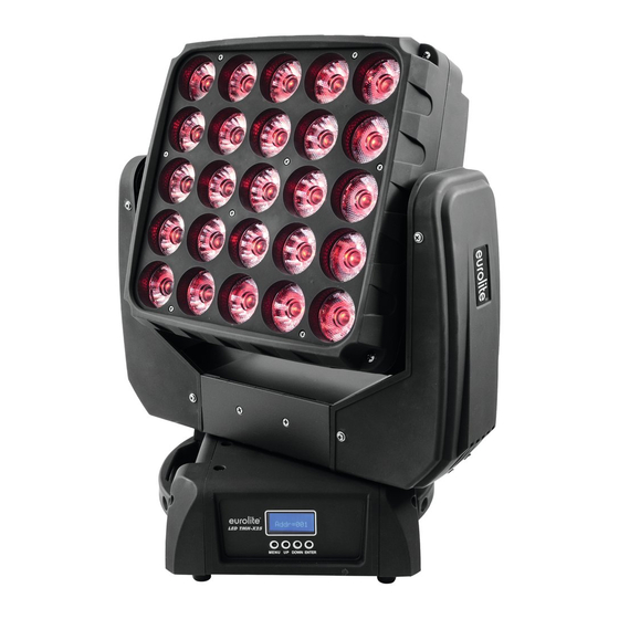
Geräteübersicht (1) Projektorarm (2) Projektorkopf (3) LEDs (4) Base (5) Tragegriff (6) Transportsicherung (7) Gummifuß (8) Display (9) Montageplatte (10) Taste nach links (11) Menu-Taste (12) Taste nach unten (13) Enter-Taste (14) Taste nach rechts (15) Taste nach oben (16) Netzwerk/Ethernet-Schnittstelle (17) Netzwerk/Ethernet-Schnittstelle (18) 5-poliger DMX-Eingang (19) 5-poliger DMX-Ausgang... -
Page 9: Installation
INSTALLATION Projektormontage Die Aufhängevorrichtungen des Projektors muss so gebaut und bemessen sein, dass sie 1 Stunde lang ohne dauernde schädliche Deformierung das 10-fache der Nutzlast aushalten kann. Die Installation muss immer mit einer zweiten, unabhängigen Aufhängung, z. B. einem geeigneten Fangnetz, erfolgen. - Page 10 Das Gerät kann direkt auf den Boden gestellt werden oder in jeder möglichen Position im Trussing installiert werden, ohne seine funktionellen Eigenschaften zu verändern. Die Projektorbase lässt sich auf zwei verschiedene Arten montieren. Sichern Sie den Projektor bei Überkopfmontage (Montagehöhe >100 cm) immer mit einem geeigneten Sicherungsseil.
-
Page 11: Anschluss An Den Dmx-512 Controller / Verbindung Projektor - Projektor
Anschluss an den DMX-512 Controller / Verbindung Projektor – Projektor Achten Sie darauf, dass die Adern der Datenleitung an keiner Stelle miteinander in Kontakt treten. Die Geräte werden ansonsten nicht bzw. nicht korrekt funktionieren. Beachten Sie, dass die Startadresse abhängig vom verwendeten Controller ist. Unbedingt Bedienungsanleitung des verwendeten Controllers beachten. -
Page 12: Betrieb Per Art-Net
Betrieb per Art-Net Für den Betrieb mit geeigneter Lichtsteuersoftware mit Art-Net-Unterstützung. Das Gerät kann über das Bedienfeld konfiguriert werden. Datenverkabelung Das Gerät ist mit RJ45-Anschlüssen zum Anschluss an einen Computer oder an ein vorhergehendes bzw. nachfolgendes Gerät ausgestattet. Die Verkabelung kann nach den folgenden zwei Installationsmethoden vorgenommen werden. Verkabeln Sie die Geräte untereinander mit Netzwerkkabeln. -
Page 13: Anschluss Ans Netz
Sie es nach rechts bis es einrastet. Stecken Sie den Netzstecker in eine geerdete Schutzkontaktsteckdose ein. BEDIENUNG Wenn Sie das Gerät an die Spannungsversorgung angeschlossen haben, nimmt der LED TMH-X25 Zoom den Betrieb auf. Während des Reset justieren sich die Motoren aus und das Gerät ist danach betriebsbereit. 13/56... -
Page 14: Control Board
Control Board Das Control Board bietet mehrere Möglichkeiten: so lassen sich z. B. die DMX-Startadresse eingeben, das vorprogrammierte Programm abspielen oder ein Reset durchführen. Drücken Sie die Menu-Taste um ins Hauptmenü zu gelangen. Durch Drücken der geeigneten Richtungstaste nach unten, nach oben, nach links und nach rechts können Sie sich im Hauptmenü bewegen. Zur Auswahl des gewünschten Menüpunktes drücken Sie die Enter-Taste. -
Page 15: Address
Celsius Temperatureinheit zwischen °C und Temperature C/F Fahrenheit °F umschaltbar Zurücksetzen auf Reset Default ON/OFF Werkseinstellungen U... White All =XXX Manual White All Funktionstest der Kanäle Test Channel White All Password Password=XXX PAN=XXX Kalibrierung; Standardposition Calibration TILT PAN=XXX Passwort „123“ ZOOM ZOOM=XXX Reset... -
Page 16: Option Config
Ethernet IP Ethernet IP Mit dieser Funktion können Sie die IP Addresse und die Subnetzmaske des Gerätes anzeigen. Software Version Software Version Mit dieser Funktion lässt sich die Software-Version auslesen. Option Config PAN TILT PAN-Umkehr Mit dieser Funktion lässt sich die PAN-Bewegung umkehren. TILT-Umkehr Mit dieser Funktion lässt sich die TILT-Bewegung umkehren. -
Page 17: Manual Control
Tastensperre Mit der Funktion “Lock On“ können Sie die Tasten des Control Boards sperren, um z.B. ein Eingreifen Unbefugter zu verhindern. Wenn diese Funktion aktiviert wurde, werden die Tasten automatisch 15 Sekunde nach dem letzten Befehl, gesperrt. Drücken Sie, um die Tastensperre zu deaktivieren oder zeitweilig zu deaktivieren und um den Zugriff auf die Menübefehle zurückzugewinnen, die Menu-Taste für 3 Sekunden. -
Page 18: Dmx-Gesteuerter Betrieb
Bitte vergewissern Sie sich, dass sich die Steuerkanäle nicht mit anderen Geräten überlappen, damit der LED TMH-X25 Zoom korrekt und unabhängig von anderen Geräten in der DMX-Kette funktioniert Werden mehrere LED TMH-X25 Zoom auf eine Adresse definiert, arbeiten sie synchron. -
Page 19: Dmx-Protokoll
DMX-Protokoll Das Gerät verfügt über vier verschiedene DMX-Kanal-Modi. Über das Control Board können Sie den DMX- Kanal-Modus definieren. Mode/Channel Decimal Hexad. Percentage S/F Eigenschaft DMX & DMX & RGBW Stan- Shape- Shape dard RGBW (DMX (DMX control) control) (Art-Net (Art-Net control)* control)* Horizontale Bewegung... - Page 20 Funktion TILT- Bewegung 127 00 7F Keine Funktion Endlose TILT-Rotation 128 189 80 BD 50% vorwärts mit zunehmender Geschwindigkeit 190 193 BE C1 75% Stopp Endlose TILT-Rotation 194 255 C2 FF 76% 100% rückwärts mit zunehmender Geschwindigkeit Zoom Bewegung Allmähliche Einstellung von 255 00 FF 100% nah bis weit...
- Page 21 72 103 48 67 28% Grün zu Cyan 104 135 68 87 41% Cyan zu Blau 136 167 88 A7 53% Blau zu Magenta 168 199 A8 C7 66% Magenta zu Rot 200 231 C8 E7 78% Rot zu Weiß Fading colors mit 232 255 E8 FF 91% 100% zunehmender...
- Page 22 Allmähliche Einstellung der Dimmerintensität von 100 255 00 FF 100% bis 0 % Zahlen und Buchstabenmotive, Motive 00 05 Keine Funktion 06 0A 0B 0F 10 14 15 19 1A 1E 10% 1F 23 12% 24 28 14% 29 2D 16% 2E 32 18% 33 37 20% 38 3C 22%...
- Page 23 196 200 C4 C8 77% 201 205 C9 CD 79% Muster 1 206 210 CE D2 81% Muster 2 211 215 D3 D7 83% Muster 3 216 220 D8 DC 85% Muster 4 221 225 DD E1 87% Muster 5 226 230 E2 E6 89% Muster 6 231 235 E7 EB 91%...
- Page 24 Blau 2 255 00 FF 100% Blau 0 - 100 % zunehmend Weiß 2 255 00 FF 100% Weiß 0 - 100 % zunehmend Rot 3 255 00 FF 100% Rot 0 - 100 % zunehmend Grün 3 10 * 255 00 FF 100% Grün 0 - 100 % zunehmend...
- Page 25 Weiß 8 32 * 255 00 FF 100% Weiß 0 - 100 % zunehmend Rot 9 25 * 33 * 255 00 FF 100% Rot 0 - 100 % zunehmend Grün 9 26 * 34 * 255 00 FF 100% Grün 0 - 100 % zunehmend Blau 9 27 *...
- Page 26 Rot 15 43 * 57 * 255 00 FF 100% Rot 0 - 100 % zunehmend Grün 15 44 * 58 * 255 00 FF 100% Grün 0 - 100 % zunehmend Blau 15 45 * 59 * 255 00 FF 100% Blau 0 - 100 % zunehmend Weiß...
-
Page 27: Reinigung Und Wartung
Grün 21 62 * 82 * 255 00 FF 100% Grün 0 - 100 % zunehmend Blau 21 63 * 83 * 255 00 FF 100% Blau 0 - 100 % zunehmend Weiß 21 84 * 255 00 FF 100% Weiß... -
Page 28: Sicherungswechsel
4) Die elektrischen Anschlussleitungen dürfen keinerlei Beschädigungen, Materialalterung (z.B. poröse Leitungen) oder Ablagerungen aufweisen. Weitere, auf den jeweiligen Einsatzort und die Nutzung abgestimmte Vorschriften werden vom sachkundigen Installateur beachtet und Sicherheitsmängel behoben. LEBENSGEFAHR! Vor Wartungsarbeiten unbedingt allpolig vom Netz trennen! Das Gerät sollte regelmäßig von Verunreinigungen wie Staub usw. - Page 29 Best.-Nr. 51786534 EUROLITE TPC-10 Klammer, silber Best.-Nr. 59006856 EUROLITE TPC-10 Klammer, schwarz Best.-Nr. 59006858 EUROLITE Sicherungsseil B 6x1000mm bis 35kg silber Best.-Nr. 58010331 EUROLITE Sicherungsseil B 6x1000mm bis 35kg sw Best.-Nr. 58010347 EUROLITE DMX Kabel XLR 3pol 3m sw Best.-Nr. 3022785H PSSO DMX Kabel XLR 3pol 3m sw Neutrik Best.-Nr.
-
Page 30: Introduction
- download the latest version of the user manual from the Internet INTRODUCTION Thank you for having chosen a EUROLITE LED TMH-X25 Zoom. If you follow the instructions given in this manual, we are sure that you will enjoy this device for a long period of time. - Page 31 If the device has been exposed to drastic temperature fluctuation (e.g. after transportation), do not switch it on immediately. The arising condensation water might damage your device. Leave the device switched off until it has reached room temperature. Please make sure that there are no obvious transport damages. Should you notice any damages on the A/C connection cable or on the casing, do not take the device into operation and immediately consult your local dealer.
-
Page 32: Operating Determinations
OPERATING DETERMINATIONS This device is a LED moving-head lighting effect for creating decorative effects. This product is allowed to be operated with an alternating voltage of 100-240 V, 50/60 Hz and was designed for indoor use only. This device is designed for professional use, e.g. on stages, in discotheques, theatres etc. Lighting effects are not designed for permanent operation. -
Page 33: Description Of The Device
If this device will be operated in any way different to the one described in this manual, the product may suffer damages and the guarantee becomes void. Furthermore, any other operation may lead to dangers like short- circuit, burns, electric shock, crash etc. WEEE Directive When to be definitively put out of operation, take the unit(s) to a local recycling plant for a disposal which is not harmful to the environment. -
Page 34: Overview
Overview (1) Yoke (2) Projector head (3) LEDs (4) Base (5) Carrying handle (6) Transport securing (7) Rubber foot (8) Display (9) Mounting plate (10) Button left (11) Menu button (12) Button down (13) Enter button (14) Button right (15) Button up (16) Network/Ethernet connector (17) Network/Ethernet connector (18) 5-pin DMX input... -
Page 35: Installation
INSTALLATION Rigging The installation of the projector has to be built and constructed in a way that it can hold 10 times the weight for 1 hour without any harming deformation. The installation must always be secured with a secondary safety attachment, e.g. an appropriate catch net. This secondary safety attachment must be constructed in a way that no part of the installation can fall down if the main attachment fails. - Page 36 The Moving-Head can be placed directly on the stage floor or rigged in any orientation on a truss without altering its operation characteristics (see the drawing). The fixture’s base enables to be mounted in two ways. For overhead use (mounting height >100 cm), always install an appropriate safety bond.
-
Page 37: Dmx-512 Connection / Connection Between Fixtures
DMX-512 connection / connection between fixtures The wires must not come into contact with each other, otherwise the fixtures will not work at all, or will not work properly. Please note, the starting address depends upon which controller is being used. Only use a DMX-cable and 3-pin or 5-pin XLR-plugs and connectors in order to connect the controller with the fixture or one fixture with another. -
Page 38: Operation Via Art-Net
Operation via Art-Net For use via appropriate lighting control software supporting Art-Net. The device can be configured through its control panel. Data Connection The device uses a RJ45 data connection for connection to a computer or a previous or subsequent device. To link all data ports the wiring can be made according to the following two installation methods. -
Page 39: Connection With The Mains
Plug the power cord into a grounded electrical outlet that matches the rated voltage of the machine. OPERATION After you connected the effect to the mains, the EUROLITE LED TMH-X25 Zoom starts running. During the Reset, the motors are trimmed and the device is ready for use afterwards. 39/56... -
Page 40: Control Board
Control Board The Control Board offers several features: you can simply set the starting address, run the pre-programmed program or make a reset. The main menu is accessed by pressing the Menu-button. Browse through the menu by pressing the direction buttons up, down, left and right. Press Enter in order to select the desired menu. You can change the selection by pressing the direction buttons. -
Page 41: Address
U... White All =XXX Manual White All Test function Test Channel White All Password Password=XXX Calibration to standard PAN=XXX Calibration position TILT PAN=XXX Password Code=123 ZOOM ZOOM=XXX Reset Reset ALL Reset all Standard Shape RGB Setting DMX channel Shape RGBW mode DMX&Net RGB DMX&Net RGBW... -
Page 42: Option Config
Software Version Software Version With this function you can display the software version. Option Config PAN TILT PAN Reverse With this function you can reverse the PAN-movement. TILT Reverse With this function you can reverse the TILT-movement. PAN degree - Select PAN-angle 630° or 540° With the function “PAN Degree”, you can select the PAN-angle. -
Page 43: Reset
Temperature C/F Switch the software temperature display between Celsius and Fahrenheit With this function you can select the temperature designation. Reset Default Reload Default With this function you can restore the factory settings of the device. The different settings (marked in the table) will be set back to the default values (shaded). -
Page 44: Dmx-Controlled Operation
DMX-protocol. Addressing The DMX starting address is defined as the first channel from which the LED TMH-X25 Zoom will respond to the controller. If you set, for example, the address in the 113 channel mode to channel 114, the device will use the channel 114 to 226 for control. -
Page 45: Dmx-Protocol
DMX-protocol The device has four different DMX channel modes. The Control Board allows you to assign the DMX channel mode. Mode/Channel Decimal Hexad. Percentage S/F Feature DMX & DMX & RGBW Stan- Shape- Shape dard RGBW (DMX (DMX control) control) (Art-Net (Art-Net control)*... - Page 46 forwards with increasing speed 193 BE C1 75% Stop Unlimited TILT rotation 255 C2 FF 76% 100% backwards with increasing speed Zoom-movement Gradual adjustment from 255 00 FF 100% near to far Shutter, strobe function 00 1F Close 20 3F 13% Open Strobe effect with 40 5F 25%...
- Page 47 Color presets 00 04 No function 05 09 White 1 0A 0E White 2 0F 13 White 3 14 18 White 4 19 1D 10% White 5 1E 22 12% White 6 23 27 14% Color preset 1 28 2C 16% Color preset 2 2D 31 18% Color preset 3...
- Page 48 10 14 15 19 1A 1E 10% 1F 23 12% 24 28 14% 29 2D 16% 2E 32 18% 33 37 20% 38 3C 22% 3D 41 24% 42 46 26% 47 4B 28% 4C 50 30% 51 55 32% 56 5A 34% 5B 5F 36% 100 60 64 38%...
- Page 49 240 EC F0 93% Pattern 8 245 F1 F5 95% Pattern 9 250 F6 FA 96% Pattern 10 255 FB FF 98% 100% Pattern 11 Patterns direction 00 31 ↑ Direction 0° 32 63 20% ← Direction 90° 149 64 95 39% ↓...
- Page 50 Red 3 255 00 FF 100% Red 0 - 100 % increasing Green 3 10 * 255 00 FF 100% Green 0 - 100 % increasing Blue 3 11 * 255 00 FF 100% Blue 0 - 100 % increasing White 3 12 * 255 00 FF...
- Page 51 255 00 FF 100% Green 0 - 100 % increasing Blue 9 27 * 35 * 255 00 FF 100% Blue 0 - 100 % increasing White 9 36 * 255 00 FF 100% White 0 - 100 % increasing Red 10 28 * 37 *...
- Page 52 255 00 FF 100% Blue 0 - 100 % increasing White 15 60 * 255 00 FF 100% White 0 - 100 % increasing Red 16 46 * 61 * 255 00 FF 100% Red 0 - 100 % increasing Green 16 47 * 62 *...
-
Page 53: Cleaning And Maintenance
255 00 FF 100% White 0 - 100 % increasing Red 22 64 * 85 * 255 00 FF 100% Red 0 - 100 % increasing Green 22 65 * 86 * 255 00 FF 100% Green 0 - 100 % increasing Blue 22 66 * 87 *... -
Page 54: Replacing The Fuse
DANGER TO LIFE! Disconnect from mains before starting maintenance operation! We recommend a frequent cleaning of the device. Please use a moist, lint-free cloth. Never use alcohol or solvents! The cooling-fan should be cleaned monthly. The interior of the fixture should be cleaned at least annually using a vacuum-cleaner or an air-jet. There are no serviceable parts inside the device. - Page 55 EUROLITE TPC-10 Coupler, silver No. 59006856 EUROLITE TPC-10 Coupler, black No. 59006858 EUROLITE Safety bond B 6x1000mm up to 35kg silver No. 58010331 EUROLITE Safety bond B 6x1000mm up to 35kg bk No. 58010347 EUROLITE DMX cable XLR 3pin 3m bk No.
- Page 56 Eurolite is a brand of Steinigke Showtechnic GmbH Andreas-Bauer-Str. 5 97297 Waldbüttelbrunn Germany D00105348 Version 1.1 Publ. 15/03/2017...
Need help?
Do you have a question about the LED TMH-X25 Zoom and is the answer not in the manual?
Questions and answers