Table of Contents
Advertisement
Advertisement
Table of Contents

Related Manuals for Procom ECON-F


Summary of Contents for Procom ECON-F
- Page 1 OPERATING INSTRUCTIONS ECON-F(GC)/F(4C)
- Page 2 INDEX 1. Introduction 2. Protection, Supervision Salient features 3. Digital Output 4. Digital Input 5. Indication 6. Front Panel Switch 7. Setting Procedure 8. Technical Specification 9. Analog Channel Data 10. Wiring Diagram 11. Dimensional Drawing Page - 1 Operating Instructions...
- Page 3 2.0 Protection, Supervision Salient Features Protection Low Lube Oil Pressure(LLOP) High Water Temp. (HWT) Fuel Level [In ECON-F(4C)only] Emergency off Oil Temperature . Charging Alternator Fail/V-Belt failure Display and Measurement Battery Voltage Engine Run Hour...
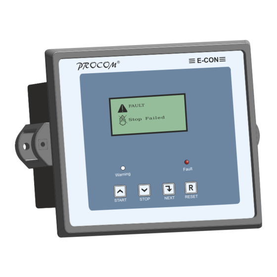
- Page 4 11. Remote Stop : ECON issues stop command to engine on receipt of DC negative at remote stop terminal 5.0 Indication Listed below are the two LED indication available on front of ECON-F/P Warning : Blinks in case of sensor open or on low fuel warning...
- Page 5 6.0 Front Panel Switch ECON – F/4C has four switch provided on its front panel. Switch can h more than one functions assigned to them. The table below describes the operation of these Switch Switch Description Symbol Function Increment Programming Mode: It is used to increment /Start the value of the parameters under programming.
- Page 6 3. Annunciation Setting l To go to next menu after generator parameter, press “Increment”. l The LCD shall display “annunciation setting”. l Annunciation settings can modified / viewed by pressing “Enter”. (for setting details pls refer table 5.1) RS-485 Parameter In ECON F (4C) only l To go to next menu after Annunciation Setting, press “Increment”.
- Page 7 10. Reset Password l To go to next menu after annunciation press “Increment”. l The LCD shall display “Reset Password”. l Password can be modified by pressing “Enter” l ECON will request for the present password, after feeding correct password change password will be requested and the password will be replaced by new password on pressing start button..
- Page 8 LLOP 1: Type A Select the installed sensors. If Type A Sensor 2: Type B no sensor is installed select 3: M&M “Disabled” 4: MNEPL 5: VE 6: TMTL 7: HUAFANG 8: TATA 9: GC(VDO) GC(Murphy 11: MVD 12: Disabled Oil Temp 1: Type A Select the installed sensors.
- Page 9 Sensor 1: Warning The action to be taken if the Warning Open 2:Fault sensor is found to be open. 3: Disabled Pulses/Re 1-300 No of pulses, from Magnetic volution Pickup unit or W point of charging alternator, in one revolution of the engine. This shall be used to calculate the RPM.
- Page 10 Maximum 600-4000 Maximum allowed RPM of 1600 Engine. Engine running at speed above this is treated as over speeding and a fault is registered and engine stopped. Minimum 600-4000 Minimum allowed RPM of 1400 Engine.running at speed below this is treated as over speeding and a fault is registered and engine Stopped.
- Page 11 Fuel Warn 25 % Monitoring value of fuel level below Disable* Level # which fuel level warning is 11-80 % generated. Fuel Warn 10 Sec Monitoring time of fuel level after 1-999Sec Delay # which fuel level warning is generated. Fuel Trip 15 % Monitoring value of fuel level below...
- Page 12 HWT Trip 1-999 Sec The duration for which the engine delay is allowed to operate at temperature higher than the above set maximum temperature ChgAlt- 1-999Sec While the engine is running and Disabled Vbelt Disabled the Charging alternator pin is not pulled low for this duration it is assumed that either the charging alternator or V-Belt has failed...
- Page 13 Ann oil 1: No Annunciation If desired, the oil temp fault can temp 2:On DO Ann1 be announced at one of the Annun- fault 3:On DO Ann2 annunciation Digital Output. ciation 4:On DO Ann3 5:On DO Ann4 1: No Annunciation If desired, the Low Fuel fault Fuel 2:On DO Ann1...
- Page 14 Parity RS 485 Communication Parity Bits None Even None Stop Bit RS 485 Communication Stop Bits Reset Service Alarm Press INC to Reset Press DEC to esc Adjust Clock Automatic real time based DG Start 00.00 00.00 & Stop (Manual Controller DD/MM/YY Configuration) RTC Time and Date can be easily entered...
- Page 15 Temp. Resistance in ohms In °C Type A Type B M&M MNEPL VE Huafang TATA TMTL (VDO) (Murphy) Water 3282 1525 3282 3282 2363 2900 3192.6 3417 10613 3512 2765 1319 2765 2765 1873 2199 2461.1 2609 7764 2707 2247 1112 2247 2247...
- Page 16 9.1 High Water Temperature Sensors Data : S.No Temperature Resistance in ohms in °C TMTL AIR3C TMTL AIR1C 279.3 273.1 258.5 246.2 237.8 223.8 208.5 201.3 193.1 185.5 177.7 169.8 162.3 146.9 138.3 131.5 122.5 116.2 106.8 100.8 85.4 76.3 61.5 57.3 46.8...
- Page 17 9.2 Low Fuel Sensors Data : S.No. Fuel in % Resistance in ohms Type A Sam_0 Sam_1 Electronics Linear 18.5 19.5 18.5 29.5 35.5. 38.5 35.5 55.5 52.5 57.5 52.5 69.5 76.5 69.5 110.5 124.5 86.5 95.5 86.5 127.5 103.5 114.5 103.5 144.5...
- Page 18 9.3 Low Lube Oil Pressure Sensors Data Pressure Resistance In Ohms In Kg/cm Type A Type B M&M MNEPL Volvo TMTL Huafang TATA (VDO) (Murphy) 16.5 16.5 20.5 19.5 20.5 23.5 23.5 30.2 30.2 41.5 28.5 41.5 49.5 58.7 49.5 40.5 62.7 58.7...
- Page 19 10.0 Wiring Diagram Page - 18 Operating Instructions...
- Page 20 11.0 Dimensional Detail...
Need help?
Do you have a question about the ECON-F and is the answer not in the manual?
Questions and answers