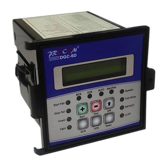
Summary of Contents for Procom DGC-6D
- Page 2 Cat/DCG-6D1I/07-08/03/Ver 1 Page 2/10...
- Page 3 Index Introduction Salient Feature of the DGC-6D 1.2.1 Protection & Supervision 1.2.2 Measurement & Display 1.2.3 LED Indications 1.2.4 Timer Function Engine solenoid Display Programming Mode 1.6.1 Setting Table Annunciation LED Functions Switch Description Fault 1.9.1 Internal Fault 1.9.2 External Fault 1.9.3 Fault Reset...
- Page 4 Unit remains fully operational even if battery voltage falls to zero volts for one sec. 1.2.2 Measurement & Display. DGC-6D, equipped with four seven segment display, displays: • • • • EB voltages of RYB phase • • • •...
- Page 5 While the genset is running, DGC-6D monitors the genset for external fault LLOP, HWT, Emergency and voltage healthiness. On detection of any fault, Gen-set is stopped by the DGC-6D after set time delay & hooter is switched on. On restoration of healthy EB supply for the set time duration the Gen-set is stopped after recooling it for the user set recooling time.
- Page 6 Manual Mode / Test In manual /Test mode the DG can start or stop by pressing Start and stop button respectively. The main contactor can be switched on and off by pressing MCB button and generator contactor can be switched on / off by pressing GCB button. Engine solenoid Engine solenoid contact (Terminal 15 &...
- Page 7 Generator is stopped by releasing fuel solenoid. Generator contactor is released and mains contactor is closed. Hooter shall be activated Generator The time for which the Generator voltage 10Sec 0-999 Supervision Time should, continuously be unhealthy to Sec. generate a fault condition. Generator O/S If the generator frequency goes beyond this 65 Hz...
- Page 8 phase mains monitoring) CT Ratio Current Transformer ratio 1-199 (Available only in DGC-6 with single phase mains monitoring) Switches Description: S.No. Switch Switch Description Symbol Function OR A/M Next Normal operation mode: In this mode, next is used to select the voltages on the display. The default voltage is mains R Phase voltage.
- Page 9 Generator Fails to Start. Corresponding LED blinks and hooter is activated Generator Voltage Unhealthy. Corresponding LED blinks and hooter is activated iii) Generator Fails to Stop. Corresponding LED blinks and hooter is activated Over-Speed. Corresponding LED blinks, hooter is activated & Genset stops. Battery Under or Over voltage.
- Page 10 Depth 120mm Digital Input Level Battery Voltage (Negative) 1.12 Connection Diagram dgc-6d Batt - Batt + Mains Sup- N Gen-N Hooter LLOP Fuel Low fuel Cran 1.13 Connection Diagram dgc-6d1I Batt - Batt + Sup-N Mains Gen-N Hooter LLOP Fuel...


Need help?
Do you have a question about the DGC-6D and is the answer not in the manual?
Questions and answers