
Related Manuals for Emerson Rosemount 2240S


Summary of Contents for Emerson Rosemount 2240S
- Page 1 Quick Start Guide 00825-0100-2240, Rev AA February 2023 Rosemount 2240S Multi-input ™ Temperature Transmitter...
-
Page 2: Table Of Contents
Quick Start Guide February 2023 Contents About this guide........................... 3 Overview............................6 General information........................8 Sensor installation........................9 Rosemount 2240S Installation....................17 Configuration and operation....................39 Emerson.com/Rosemount... -
Page 3: About This Guide
For equipment service or support needs, contact your local Emerson Automation Solutions/Rosemount Tank Gauging representative. Spare Parts Any substitution of non-recognized spare parts may jeopardize safety. - Page 4 Ensure the mains power to the device is off and the lines to any other external power source are disconnected or not powered while wiring the device. WARNING Electrical shock could cause death or serious injury. Use extreme caution when making contact with the leads and terminals. Emerson.com/Rosemount...
- Page 5 February 2023 Quick Start Guide WARNING Physical access Unauthorized personnel may potentially cause significant damage to and/or misconfiguration of end users’ equipment. This could be intentional or unintentional and needs to be protected against. Physical security is an important part of any security program and fundamental to protecting your system.
-
Page 6: Overview
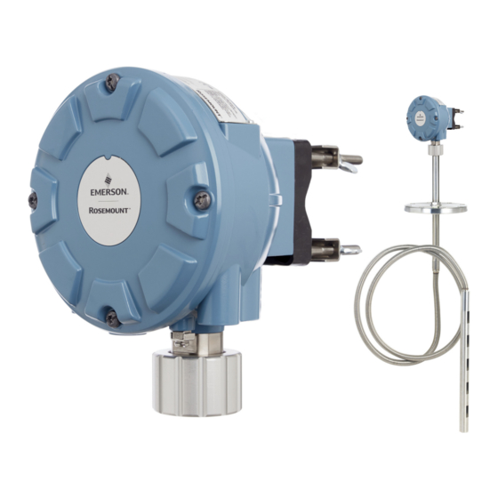
February 2023 2 Overview 2.1 Components Figure 2-1: Rosemount 2240S Components A. Cover. B. Entries (x 3) of type ½ - 14 NPT. C. Lock nut for connection of Multi Spot Temperature sensor and Water Level Sensors. D. Cover screws (x 4). - Page 7 4. Connect the Rosemount 2410 Tank Hub to the Rosemount 2460 System Hub. 5. Connect the field devices, such as a Rosemount 5900S Radar Level Gauge and a Rosemount 2240S Multi-input Temperature Transmitter, to the Rosemount 2410 Tank Hub via the Tankbus.
-
Page 8: General Information
3 General information 3.1 Service support For service support contact the nearest Emerson Automation Solutions /Rosemount Tank Gauging representative. Contact information can be found on the web site www.Emerson.com. 3.2 Product certifications See the Rosemount 2240S Product Certifications document for detailed information on the existing approvals and certifications. -
Page 9: Sensor Installation
Temperature and Water Level Sensors should be located as far away as possible from heating coils and mixers. • In case the flexible tube is damaged, please contact Emerson Automation Solutions/Rosemount Tank Gauging. • Do not attempt to fix or rebuild the temperature sensor since this... - Page 10 B. Recommended: 0.5 to 1 m (1.6 to 3.3 ft) below maximum filling level C. Upper spot element D. First spot element E. Minimum 1 m (3.3 ft) F. Anchor weight G. 2-15 kg (4.4-33 lbs) H. 150-350 mm (5.9-13.8 in.) Emerson.com/Rosemount...
- Page 11 February 2023 Quick Start Guide 4.2.2 Installation on floating roof tanks On floating roof tanks the temperature elements can be mounted in a still-pipe as illustrated in Figure 4-2 or in other suitable roof openings. Figure 4-2: Installation of Multiple Spot Temperature Elements in Still-pipe A.
- Page 12 Quick Start Guide February 2023 illustrated in Figure 4-3. Emerson Automation Solutions may in some cases recommend even more temperature elements for Custody Transfer tanks, depending on how the tanks are operated. Figure 4-3: Recommended Position of Temperature Elements for Custody Transfer Applications Min.
- Page 13 February 2023 Quick Start Guide Manual for more information about how to use the TankMaster WinSetup software to configure temperature elements for average temperature calculations. 4.3 Water Level Sensor The water level sensor (WLS) probe, with integrated temperature elements, is attached at the lower end of the flexible protection tube. A weight is attached to stabilize the tube as illustrated in Figure 4-4.
- Page 14 B. 350 mm (13.8 in.) C. Upper Sensor Limit (100%) D. Lower Sensor Limit (0%) E. WLS Probe Active Length Standard: 500 mm (19.7 in.) Option: 1000 mm (39.4 in.) F. Weight G. Recommended minimum distance: 1 m (3.3 ft) Emerson.com/Rosemount...
- Page 15 February 2023 Quick Start Guide 4.4 Installing a temperature sensor tube Follow these steps to install the temperature sensor tube: Procedure 1. Mount the anchor weight on the tube. 2. Mount the tube so that the threads at the top of the tube fits the nozzle flange as illustrated in Figure 4-5.
- Page 16 If a weight is placed at the end of the tube, it should barely touch the tank bottom. Note Ensure that the flexible protection tube is in a vertical position to obtain correct measurement data. 4. Install the Rosemount 2240S Multi-Input Temperature Transmitter. Emerson.com/Rosemount...
-
Page 17: Rosemount 2240S Installation
Ensure that the Rosemount 2240S is installed such that it is not exposed to higher pressure and temperature than specified in Product Data Sheet. - Page 18 Sensor installation. Procedure 1. Unscrew the four screws and remove the cover. A. Cover B. Cover screws (x4) C. Plug 2. Remove the plug that protects the cable entry at the bottom of the Rosemount 2240S transmitter housing. Emerson.com/Rosemount...
- Page 19 February 2023 Quick Start Guide 3. Attach the Rosemount 2240S transmitter on top of the temperature sensor tube. A. Terminal compartment B. Sensor wires C. Sensor tube 4. Run the sensor wires into the terminal compartment. 5. Tighten the nut on the transmitter by hand.
- Page 20 4. Proceed with electrical installation of Tankbus, temperature elements, and water level sensor. 5.2.3 Wall mounting To mount the Rosemount 2240S on a wall, do the following: Procedure 1. Drill four 9 mm (0.35 in.) holes in the wall to fit the hole pattern of the bracket.
- Page 21 Countersunk screws are not suitable. 70 mm (2.7 in.) Ø 9mm (0.35 in.) 94 mm (3.7 in.) 3. Attach the Rosemount 2240S transmitter to the bracket and tighten the screw. Postrequisites Proceed with electrical installation of Tankbus, temperature elements, and water level sensor.
- Page 22 A. Sensor wires B. Sensor fittings C. Holes for sensor wires D. Flange 2. Torque the sensor fittings to the recommended value of maximum 16 Nm. See drawing D7000 005-451. Note that sensor fittings should not be opened once installed. Emerson.com/Rosemount...
- Page 23 A. Connection cone B. Gasket C. Flange 4. Pull the wires up through the opening at the top of the connection cone. 5. Remove the cover from the Rosemount 2240S terminal compartment. Quick Start Guide...
- Page 24 D. Connection cone 7. Tighten the nut by hand. 8. Run the temperature sensor wires through the sleeve at the bottom of the transmitter housing into the terminal compartment. Postrequisites Wire the temperature sensors to the Rosemount 2240S transmitter terminal block. Emerson.com/Rosemount...
- Page 25 The electronics housing has three entries for ½ - 14 NPT glands. Optional M20×1.5, minifast and eurofast adapters are also available. For remote mounting, the nut and sleeve on the Rosemount 2240S can be replaced with a M32 gland for connection of temperature sensors/WLS.
- Page 26 Quick Start Guide February 2023 5.3.2 Power requirements The Rosemount 2240S temperature transmitter is powered over the Tankbus by the Rosemount 2410 Tank Hub. The Rosemount 2240S has a current consumption of 30 mA. When installed in a F Fieldbus system, the Rosemount ™...
- Page 27 “daisy-chained” Tankbus cables. 5.3.4 Cable selection Use shielded twisted pair wiring for the Rosemount 2240S in order to comply with FISCO requirements and EMC regulations. The preferred cable is referred to as type “A” fieldbus cable. The cables must be suitable for the supply voltage and approved for use in hazardous areas, where applicable.
- Page 28 Rosemount 2240S coding automatically becomes Ex ib. This means that, in this case, neither the Rosemount 2240S itself nor any RTD or other sensors connected to the RTD terminals or RS485/ Modbus terminals of the Rosemount 2240S may be located in Zone 0.
- Page 29 Rosemount 2240S Multi-input Temperature Transmitter also have built-in terminators which can easily be enabled by inserting a jumper in the terminal block when necessary. If the Rosemount 2240S is not the last device in the fieldbus network, disconnect the termination jumper. Segment design When designing a FISCO fieldbus segment a few requirements need to be considered.
- Page 30 4. Connect the Tankbus wires to the X2 and X3 terminals. 5. Connect the cable shield to the terminal marked X1. 6. In case the Rosemount 2240S is installed at the end of a Tankbus network, enable the termination by using a jumper between terminals X3 and X4.
- Page 31 February 2023 Quick Start Guide Terminal compartment Figure 5-3: Rosemount 2240S Terminal Compartment A. X1: Cable Shield B. Internal grounding terminals C. X2: Tankbus (+) output D. X3: Tankbus (-) output E. Daisy-chain connection to other field devices F. Jumper to invoke built-in termination G.
- Page 32 2. Loosen the four screws and remove the cover from the terminal compartment. 3. Disconnect the termination jumper from the X3 terminal. 4. Run the Tankbus cable into the Rosemount 2240S through an appropriate gland. 5. Connect the Tankbus wires to the X2 output and X3 output terminals.
- Page 33 3-wire individual spot, and 4-wire individual spot. The Rosemount 2240S is also compatible with averaging sensor types. A maximum of 16 elements can be connected to a Rosemount 2240S transmitter. The Rosemount 2240S is also equipped with a RS485/Modbus terminal for connection of a Water Level Sensor.
- Page 34 Rosemount 2240S housing. In case a Rosemount 2240S is mounted on a pipe or a wall, the sleeve and nut can be replaced by an M32 cable gland.
- Page 35 3. Run the wires for temperature elements and water level sensor through the sleeve at the bottom of the transmitter housing. If the Rosemount 2240S transmitter is mounted on a wall or pipe (remote mounting), run the sensor wires through the appropriate cable gland/conduit entry.
- Page 36 The following wiring methods are supported: Figure 5-6: 3-wire with Common Return c1 d1 Up to 16 channels Common return Note Black wires (common/individual return) must always be connected to the c- and d- terminals on left-hand side of the terminal block. Emerson.com/Rosemount...
- Page 37 February 2023 Quick Start Guide Figure 5-7: 3-wire Individual Spot c1 d1 b2 c2 d2 b3 c3 d3 b16 c16 d16 Up to 16 channels Individual return Figure 5-8: 4-wire Individual Spot b1 c1 d1 a2 b2 c2 d2 a3 b3 c3 d3 c16 d16 Up to 16 channels Individual return...
- Page 38 Quick Start Guide February 2023 Cable color coding Table 5-3: Cable Colors for the Rosemount 565/566/765 Temperature Sensors Temperature Element Color Brown Orange Yellow Green Blue Violet Grey White Pink Brown/Black Red/Black Orange/Black Yellow/Black Green/Black Blue/Black Emerson.com/Rosemount...
-
Page 39: Configuration And Operation
It is important that configuration is properly prepared by listing the appropriate Modbus addresses, device tags, and tank tags. 6.1.1 Configuration procedure Basically, a Rosemount 2240S can be installed and configured by one of the following methods: • As part of the installation of a Rosemount 2410 Tank Hub. This is... - Page 40 (difference between tank zero level and water zero level) • probe length • upper and lower dead zone 6.1.3 Configuration tools Different tools are available for configuration of a Rosemount 2240S: • Rosemount TankMaster Winsetup • Field Communicator • AMS Device Manager for F Fieldbus systems ™...
- Page 41 14 temperature spot elements. However, Average Temperature will be correctly calculated by a Rosemount 2410 Tank Hub connected to a Rosemount 2240S with 16 temperature elements regardless if the tank hub is connected to a Rosemount 2460 or a Rosemount 2160.
- Page 42 You can specify a minimum distance between the product surface and the first temperature spot element to be included in the average temperature calculation. If the temperature spot element is within or above the Insert Distance, the element will be excluded from the calculation. Emerson.com/Rosemount...
- Page 43 10 mm will guarantee that sensors above the surface are not included in the average temperature calculations. 6.3 LED signals The Rosemount 2240S Multi-input Temperature Transmitter is equipped with Light Emitting Diodes (LED) in order to indicate status and communication. Quick Start Guide...
- Page 44 When an error occurs, the LED flashes a sequence that corresponds to a code number followed by a five second pause. This sequence is continuously repeated. 6.3.2 Communication LEDs There are two pairs of LEDs that indicate communication status for the Rosemount 2240S Multi-input Temperature Transmitter: Emerson.com/Rosemount...
- Page 45 February 2023 Quick Start Guide • when a Water Level Sensor (WLS) is connected, two LED signals indicate that measurement and status information is communicated over the Sensor bus to the temperature transmitter • two LEDs indicate that the temperature transmitter communicates with a Rosemount 2410 Tank Hub over the Tankbus Figure 6-4: Communication LEDs...
- Page 46 Quick Start Guide February 2023 6.4 Switches and reset buttons 6.4.1 DIP Switches The Rosemount 2240S is equipped with four DIP switches, see Figure 6-5. Figure 6-5: DIP Switches The switches control the following settings: Table 6-2: DIP Switches Number Function...
- Page 47 The write protect switch The Write Protect switch prevents unauthorized configuration changes by locking the Rosemount 2240S database registers. Configuration using the Average DIP switch The Average switch enables configuration of the Rosemount 2240S according to the default settings in Table 6-3.
- Page 48 Tank Gauging system. See the Rosemount Tank Gauging System Configuration Manual for more information on how to configure Auxiliary Tank Devices (ATD) such as the Rosemount 2240S. 6.5.1 Advanced configuration Average temperature calculation weight factor You can specify a weight factor for each temperature element used in the tank average temperature calculation.
- Page 49 February 2023 Quick Start Guide • a formula • an individual formula for each temperature element Adjustment after sensor calibration If the temperature sensor was ordered with sensor calibration including Callendar-Van Dusen constants the constants must be entered for each individual element using the conversion method "User Defined Individual Formula"...
- Page 50 Quick Start Guide February 2023 Emerson.com/Rosemount...
- Page 51 February 2023 Quick Start Guide Quick Start Guide...
- Page 52 2023 Emerson. All rights reserved. Emerson Terms and Conditions of Sale are available upon request. The Emerson logo is a trademark and service mark of Emerson Electric Co. Rosemount is a mark of one of the Emerson family of companies. All other marks are the property of their respective owners.
Need help?
Do you have a question about the Rosemount 2240S and is the answer not in the manual?
Questions and answers