Table of Contents
Advertisement
Quick Links
- 1 Base Unit
- 2 Programming the Ls-20 through Usb to Connecting to Gsm Network
- 3 Access Ls-20 by Hypersecurelink Software or Mobile App. from Local Network
- 4 Works with Hypersecurelink Software or Mobile App. (Myhome) from Internet
- 5 4, Installation
- 6 Appendix A: Ethernet Interface Settings
- 7 Appendix B: Wifi Interface Settings
- Download this manual
Advertisement
Table of Contents

Summary of Contents for FineControl LS-20
- Page 1 HOME MANAGEMENT GATEWAY OPERATION MANUAL V1.03...
-
Page 2: Table Of Contents
3, Working Scenario 3.1 Programming the LS-20 through USB to connecting to GSM network 3.2 Access LS-20 by HyperSecureLink software or Mobile App. from local network 3.3 Works with HyperSecureLink software or Mobile App. (MyHome) from Internet 3.4 Connects to a Cloud Server to Get Full Home Management Service 3.5 Connects to a Central Monitor Station to Get Alarm Service... -
Page 3: Introduction
Internet. The LS-20 not only provides you a secure life but also a convenient living environment that allows you to control remote switches through a cloud server, mobile App. or PC by using HyperSecureLink software from all over the world. -
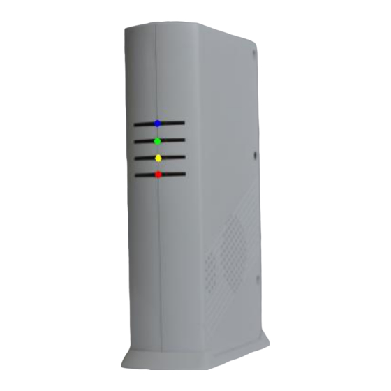
Page 4: Base Unit
1. BASE UNIT 1.1 Display The Blue LED flashes when there is data sending out from the LS-20. Three LEDs in green, yellow and red colors represent the system operation mode and alarm/ warning status as listed in the following table. -
Page 5: Rear Panel
Clear LED Status: Press the button for about 0.2 sec. to clear the alarm and warning LED status. The LED status also can be cleared from HyperSecureLink command. Device Enroll: Press the button for about 3 sec. the LS-20 enters into Enroll Device State for 30 seconds. (Buzzer beeps and Green, Yellow, Red LEDs flash) Please refer to Section 4.1. - Page 6 1.4 Beeps & LED indication (without audio board) Status Beep Remark PWR On (OK) Beeps on operation mode Disarm Monitor Home Away Clear (OK) Entry Delay M-M-M--( >10sec.) S-S-S--- (< 10sec.) Exit Delay M-M-M--( >10sec.) S-S-S--- (< 10sec.) Open Detect 5sec.
-
Page 7: 2, External Control And Indicator Connection Diagram
2, External Control and Indicator Connection Diagram... -
Page 8: 3, Working Scenario
(MyHome) or connect to a cloud server to enjoy much more service from the provider. 3.1 Programming the LS-20 through USB to connecting to GSM network. Note: For the LS-20 with only GSM communication module, please use USB and HyperSecureLink software to set the operation parameters. -
Page 9: Access Ls-20 By Hypersecurelink Software Or Mobile App. From Local Network
Connecting the LS-20 to a router to be accessed by Mobile App. (MyHome) or HyperSecureLink software locally. Find the LS-20 address by VCOM and set LS-20 as a server from its web page. Access the LS-20 by HyperSecureLink software or Mobile App. from local. -
Page 10: Works With Hypersecurelink Software Or Mobile App. (Myhome) From Internet
2, The LS-20 has to be mapped to a TCP port that can be accessed from Internet by virtual server or port forwarding function in the router. (Ex: Using the free Domain Name Service from the router manufacturer DLINK and... -
Page 11: Connects To A Cloud Server To Get Full Home Management Service
3.4 Connects to a Cloud Server to Get Full Home Management Service Note: LS-20 must be set as a client. Ex.: Assign LS-20 to the Livingpattern cloud service. Service example from Livingpattern cloud server. -
Page 12: Connects To A Central Monitor Station To Get Alarm Service
3.5 Connects to a Central Monitor Station to Get Alarm Service. Before connecting to a CMS service provider, please consult your distributer first. Note: LS-20 must be set as a client. CMS monitoring software example from a service provider. -
Page 13: 4, Installation
4, Installation 4.1 Device Enroll The first step to start the operation of LS-20 is to enroll all the sensor/controller devices into the Base Unit one by one. (Please refer to the User Guide of the devices to be enrolled as well.) *Press the Clear/Enroll button for 3 seconds, the LS-20 enters into Enroll Device State for 30 seconds. -
Page 14: Placement Of The Base Unit And Sensors
4.2 Placement of the Base Unit and Sensors It is important for the Base Unit to have a good reception quality for the RF signals transmitted from all the sensors and controllers. Place the Base Unit near the central of your home or business if possible. ... -
Page 15: 5, Operation Mode
(0-255 seconds) Set AWAY mode Note: When you set the LS-20 in AWAY Mode, the Base Unit clears any previous alarm and warning status on the LED and check the state of the Door Magnet sensors. If any of the sensors is still open (for example, you forgot to close the back door before you leave), the Base Unit will issue a 5 sec. -
Page 16: Home Mode:
Note: When you set the LS-20 in Home Mode, the Base Unit will check the status of the Door Magnet sensors. If any of the sensors is still open (for example, you forgot to close the back door), the Base Unit will keep a “Protection Loop Open”... -
Page 17: Away Mode
5.3 DISARM/ MONITOR Mode: The LS-20 will not issue any alarm for Burglar sensors, but 24-Hour sensors, Fire sensors, Panic, Medical Buttons and Environment sensors still work all the time. Enter into “DISARM” or “MONITOR” Mode from different devices or services. -
Page 18: Reaction Of Ls-20 To Other Alarms Except Burglar Alarm
5.5 Reaction of LS-20 to Other Alarms except Burglar Alarm Alarm → Warning Beep/Voice Delay (if any) Any Operation Mode ↑ ↑ (30 seconds) Sensor triggered Siren goes off, Alarm data out. Fire, Panic, Medical and Environment alarms can be triggered anytime, regardless of the system operation mode. -
Page 19: 6, System Check
6. SYSTEM CHECK 6.1 Event Log: The Base Unit can store 512 event records in its memory. These events can be checked from HyperSecureLink Software or Mobile App (MyHome). If user applies a Cloud Service then much deeper Event Log can be recorded. Event Log read from HyperSecureLink software Event Log read from a mobile App. -
Page 20: Device Status
6.2 Device Status: The latest state of the sensors including, signal strength and readings can be checked by device status from the HyperSecureLink Software or Mobile App (MyHome). If user applies a Cloud Service then each device can be named for easy identification and Environment readings or activities can be show in graphics. - Page 21 Cloud server allows user to assign a name to each device for user to identify the sensor much easier. Device Status read from a Cloud Server. 24 Hours history of a CO2 sensor shown from a Cloud Server.
-
Page 22: 7, Home Automation Control
7. HOME AUTOMATION CONTROL There are 16 (#1~#16) X-10 switches and 8 (#1~#8) RF switches can serve as alarm indications or home appliances control purpose. These switches can be controlled by Remote Controller, Keypad locally, HyperSecurelink software, mobile App (MyHome) or Cloud Server remotely. Note: Switch #16 is for Arm/ Disarm indication, please refer to 8.9, #16 SW Assignment. -
Page 23: Switch Control From Keypad
7.3 Switch control from Keypad. (Please refer to the KP-3S User Guide for more information.) 7.4, Automatic controlled by Burglar Sensors with “Home Automation=Yes” in Disarm Mode. Ex. Below settings will turn the switch #3 on for 10 minutes when the Burglar Sensor 01-02 was triggered in Disarm Mode. -
Page 24: Automatic Control By The Special Sensors With Their "High/Low" Limit Settings
7.5 Automatic control by the Special Sensors with their “High/Low” limit settings. Ex, Below settings will turn on switch #3 when reading is above “28” and turn off switch #3 when reading is below “26”. (Note: “High Limit” Control is for cooler, and “Low Limit” Control is for Heater) 7.6 Automatically switch control scheduled by HyperSecureLink software. -
Page 25: 8, Control And Parameter Settings
8. CONTROL AND PARAMETER SETTINGS 8.1 Control * Siren Test: This test will activate the beeper, external alarm siren and send an Activate signal to the Remote Siren (if a remote siren is installed) immediately. (HyperSecureLink) (Livingpattern Cloud Service) * Clear Status: To Clean the alarm/ warning LED and stop the alarm/ warning reaction. (HyperSecureLink) (Livingpattern Cloud Service) (MyHome App.) -
Page 26: Settings For Timers
8.2 Settings for Timers *Entry Delay ( For Burglar Sensor only, 0-255 seconds, default =10 sec.) This setting is the time between any burglar sensor triggers and the alarm action procedure starts. When you return home and open the door, the Base Unit will issue warning beeps (if the Delay Activation = On) to remind you that the system is still in the Arm state and you should disarm the system within this time. - Page 27 RF signals to the Base Unit at a certain time interval. If the Base Unit does not receive the RF check signal from a supervised sensor within the Sensor Supervise Time, the LS-20 considers this sensor to be missing and issues a warning message.
- Page 28 *Remote Siren Time: 0 seconds to 30 minutes (default = 60 sec.) The time of the wireless Remote Siren sounds when the alarm trips. ( Remote Siren is an Option.) * Pre-warning Time: 0-30min. (default = 2 min.) The switch action time when triggered by a Pre-warning Burglar sensor. *Home Automation Time: 0-30min.
-
Page 29: Setting For Sound & Siren
8.3 Setting for Sound & Siren * Record /Playback Voice: After an alarm call connects successfully, the LS-30 will play the prerecorded voice message that corresponds to the alarm type. The messages should be recorded in their specified segments. Common Segment (13 seconds): The voice to be played during all alarm types. This segment should contain your name, address and telephone number. - Page 30 *Tamper Siren In Disarm: (default = Off) Some of the sensors (Door Magnet, PIR, Keypad) have a Tamper sensor inside, if it was detached from the wall or the case was opened then the sensor would issue a “Tamper” signal to the Base Unit.
- Page 31 * Inner Siren: ON/OFF (default, ON) Inner Siren On: Enable the Inner Siren. Inner Siren Off: Switch off the Inner Siren. (The Siren keeps silent in alarm and warning states.) The conditions for the Inner Siren to go off when alarm trips: 1.
-
Page 32: Device Status Settings
8.4 Device Status Settings: *Device Bypass (default= No): (For all devices) Bypass = Yes: The system will ignore the trigger signal from this sensor. *Delay Activation(default= Yes): (For Controller & Burglar sensor) Delay Activation =Yes: (Refer to Exit Delay/Entry Delay.) For the Remote Controller, the Exit Delay time will be imposed on the Away command from this controller. - Page 33 *24-Hour Zone (default = NO): (For Burglar sensor) 24-Hour Zone=YES: This Burglar sensor’s trigger signal will be processed all the time regardless of the system’s operation mode, either in Arm or Disarm. 24-Hour Zone=NO: This Burglar sensor’s trigger signal will only be processed in Arm Mode. *Guard in Home Mode (PIR default = No, Door Magnet default = Yes): (For Burglar sensor) Home Mode =Yes: This Burglar sensor will trigger an alarm in Home Mode operation.
-
Page 34: Special Settings For Environment Sensor
Inactivity Time (refer to Inactivity Time), the Inactivity Alarm (medical) will be issued. Note: “Inactivity” function will be disabled in “Away” mode automatically and will issue alarm if the Inactivity sensor is triggered. Inactivity=No: This is a normal Burglar Sensor. *Supervised: (Automatically set by the sensor itself, refer to Sensor Supervise Time.) Supervised =Yes: System will check the “heartbeat”... - Page 35 “Control High Limit” then the corresponding switches will turn on and when the reading is below the “Control Low Limit” the corresponding switches will turn off. Low Limit: For the control of heater type device, it means when the reading is below the “Control Low Limit”...
-
Page 36: Wire Sensor Input Settings
8.6 Wire Sensor Input Settings Trigger Open/Close (default, Trigger = Close): Alarm will be triggered by close (grounded) or open (>3V) the sensor input contact (or voltage). Away Open/Close (default, Away = Close): (For Wire Sensor input assigned as a Controller only) System will enter Away or Disarm Mode by close (grounded) or open (>3V) the sensor input contact (or voltage). -
Page 37: Misc. Settings
8.8 MISC. Settings * Deny Arm If Not Ready: (default, No) If set “yes” then system will not enter into “Away” or “Home” Mode if not all the Door/window Magnet s are closed. Note: If “Away” or “Home” control is remotely issued by command from HyperSecureLink, App. -
Page 38: Cms Settings
The user account (8 digits Max.) number for CMS IP Alarm Report. * Mode Change Report: Enable /Disable (default=Disable, for phone number CMS only.) Mode Change Report Enable: The LS-20 will report to the CMS phone number if the operation mode (Away/Home/Disarm) has been changed. -
Page 39: Scheduling
8.10 Scheduling. *Auto Switch: In every weekday user can program the On/Off time for each switches, total 20 items can be assigned. (Please refer to 7.6) *Auto Operation: In every weekday user can program the Arm/Disarm time for the system, total 20 items can be assigned. - Page 40 *Switch Scene: 8 switch scenes can be set and controlled by KP-3S Keypad. Ex.: If Scene 4 is selected by KP-3S then switch 1 to 4 will be turned on. *Operation Scene: 8 operation scenes can be set and controlled by KP-3S Keypad Ex.: If Scene 2 is selected by KP-3S then Partial Zone 91, 92, 93 will enter into “Away Mode”.
-
Page 41: Specification
SPECIFICATIONS Input Power: 7V DC or Micro USB input. Standby Current: About 280mA (LS-20E), 320mA (LS-20EG) RF : (Follows local regulations, other frequencies as requested) Receiving Frequency: 915MHz (For FCC), 868MHz (For CE), 433MHz. Transmission Frequency: 433MHz Data Modulation: OOK (On Off Key). Power: less than 10mW. -
Page 42: Appendix A: Ethernet Interface Settings
HyperSecureLink software or mobile App MyHome. It also can be configured as a client to send poll/alarm signal to a web server or CMS (Central Monitoring Station) service provider. A1, System connection diagram for LS-20 as a server to be accessed by the HyperSecureLink Software or mobile App MyHome from Internet. - Page 43 Ex: The internal IP address of 192.168.0.90 and port number 1690 is assigned in the Virtual Server table. (This IP address and port number will be used to communicate with the LS-20 by HyperSecureLink program or mobile Apps.) A1.3, Configure the Ethernet Adaptor * RUN the VCOM program on your PC.
- Page 44 * The VCOM software searches in the network for the LS-20 Ethernet Interface and shows the findings on the screen. * Open the Internet browser you are using and enter the IP address. admin * Enter User Name and Password. (Default User Name: admin, default Password: admin.
- Page 45 * The setup menu of Administrator Setting will be shown on the screen and change the parameters according to your network environment. Nickname: Name or location of the system. IP Address: As the setting of the Virtual Server in the Ethernet Router. Subnet mask: 255.255.255.0 Gateway: Please enter the gateway address of your Ethernet Router.
- Page 46 If the IP address has been changed then enter the new IP address and User Name/ Password to access the Ethernet Adaptor setup web page again. (You can use VCOM software to locate the new IP address.) * Select TCP Mode and change the settings according to your network environment: Telnet Server/Client: Select Server.
- Page 47 * Select UART to check if the settings are the same as below. Mode: RS-232. Baudrate: 9600. Character Bits: 8. Parity Type: None Stop Bit: 1. Hardware Flow Control: None. Delimiter: No need * If any of the settings has been changed then double click the Update to update the settings. Then Click the Reset to save the settings.
- Page 48 A2, System connection diagram for LS-20 as a client to send signal to a cloud server or Central Monitoring Station through Internet. (This setting is only valid for the user who has CMS or cloud services. User has to know the IP address and port number of the CMS or cloud server before setting the Adaptor.)
- Page 49 A2.2, Configure the Ethernet Adaptor * RUN the VCOM program on your PC, check “Device Info”. Click the Search * The VCOM software searches in the network for the LS-20 Ethernet Interface and shows the findings on the screen.
- Page 50 * Open the Internet browser you are using and enter the IP address. admin * Enter User Name and Password. (Default User Name: admin, default Password: admin. * The setup menu of Administrator Setting will be shown on the screen and change the “IP Configure”...
- Page 51 Note: If you change the User Name and Password, please make sure that you write them down on a paper otherwise if you forget the new User Name and Password then this adaptor will not be accessable any more. * If any of the settings has been changed then double click the Update to update the settings. Then Click the Reset to save the settings.
- Page 52 * Select UART to check if the settings are the same as below. Mode: RS-232. Baudrate: 9600. Character Bits: 8. Parity Type: None Stop Bit: 1. Hardware Flow Control: None. Delimiter: No need * If any of the settings has been changed then double click the Update to update the settings. Then Click the Reset to save the settings.
-
Page 53: Appendix B: Wifi Interface Settings
Since the wifi Interface needs to communicate with your wifi router, please locate the LS-20 near your wifi router to keep good signal quality. B1, Search all the wifi networks in your environment from PC, tablet or mobile phone. You will find a network SSID as ”... - Page 54 B3, Open the browser and enter http://10.10.100.254 Use admin/admin to enter the wifi Adaptor setting web page. Note: If you change any setting below, only “Restart” the wifi Adaptor after all the changes of the setting had been saved. B4, Skip this Setting.
- Page 55 B5, Click “System” to show the settings in the wifi Adaptor. B6, Click “STA Setting”, it should be like the screenshot below, otherwise change the settings then click “Scan”.
- Page 56 Select your router and enter the parameters needed for the wifi Adaptor to connect to your router then click “Save”.
- Page 57 Do not click “Restart” B7, Click “AP Setting”, it should be the same as the screenshot below, otherwise change the setting as below then click “Save”.
- Page 58 B8, Click “Network”, select the protocol and set the Port ID number and Server Address as required then click “Save”. Below example is for the linking to “Livingpattern” cloud services. TCP-Server: To work with HyperSecureLink software or MyHome App, only port ID is needed. TCP-Client: To link to Cloud server like Livingpattern or Webehome, both Port ID and Server Address are needed.
-
Page 59: Appendix C: The Gsm/Gprs Setting In Ls-20Eg/Ls-20Gv
Appendix C: The GSM/GPRS setting in LS-20EG/LS-20GV The GSM module in LS-20EG/LS-20GV can work in either GSM mode or GPRS mode upon request, but you need to specify when you place the order. C1, Work in GSM mode C1.1 Turn off the PIN code of the SIM card on other mobile phone before using it in LS-20EG/LS-20GV. C1.2 Disconnect the power adaptor and use a straightened paper clip to stick in the hole of “Bat.”... - Page 60 * Alarm Report: (default SMS+Voice) User can select the GSM calls are SMS plus Voice Call or send SMS only. Note: To select SMS+Voice, LS-20 will sends all SMS messages first then dial the voice call one by one. You can click the icon to see the explanations;...
- Page 61 C1.5 To record the voice that will be heard in the voice call. After click the icon, please keep about 20 cm away from LS-20EG/LS-20GV microphone and speak clearly. Likewise, you can click the to show the explanation and examples as below. explanation and examples as below.
- Page 62 C 1.6 How to answer alarm call from LS-20. When you receive a call from LS-20, you can follow the procedures below to communicate with the system. You will hear the prerecorded message twice, which tells you what event happened to the system.
- Page 63 C2, Work in GPRS mode (Note: GPRS only can play the role as a “Client”.) C2.1 Turn off the PIN code of the SIM card on other mobile phone before using it in LS-20EG/LS-20GV. C2.2 Disconnect the power adaptor and use a straightened paper clip to stick in the hole of “Bat.” to turn off the backup battery C2.3 Insert the SIM card to the slot then reconnect the power.
- Page 64 C2.4.2 Select the “CMS Report” and “TCP/IP Alarm Report” as below. C2.5 Register the LS-20EG/ LS-20GV to the cloud server and connected the Ethernet cable. Please press “Clear” button on the base unit and open the web page of the cloud server from your PC to check if the connection to the server is successful.
-
Page 65: Appendix D: Hypersecurelink User Guide
Appendix D: HyperSecureLink User Guide: D1, Hardware Installation: D1.1, Connect by USB cable in local setting. D1.2, Connection Diagram for Internet Remote Access (For the setting of the Ethernet Interface please refer to Appendix A 1.1~1.3) - Page 66 D2, Software Installation: HyperSecureLink software can run on Windows PC or Apple Mac. For Windows PC, please open the HyperSecureLink-winxxx-SetupFiles and run the setup file. For Apple Mac, please open the HyperSecureLink-macxxx-SetupFiles and run the setup file. Follow the wizard to complete the setup. Then run the program...
- Page 67 D3, Select Link D3.1 Using USB interface to access the LS-20. Select USB . The software will scan the USB ports that are available in your PC. Select the correct one to use. D3.2 Using Ethernet interface to access the LS-20 D3.2.1, Select Ethernet (Remote) .
- Page 68 Sensor Reading are recalled, the software will match the “User Name/ Device Type/ Zone Number” under in the Data Base and show the corresponding device name on the table. Password: If the setting of the LS-20 Base Unit “ Control Command Password = Enable” then you should enter the passwords.
- Page 69 D5, Operation Select the function from the Menus bar. * Click down arrow to select the options. * Update the setting of the LS-20 Base Unit by clicking * Read the status from the LS-20 Base Unit by clicking Down arrow...
- Page 70 *Monitor: This function will check the Event log in every 30 seconds and update Device Status in every 5 minutes automatically after start. If you want to change the event read number or another device type then you have to stop the reading first. Save to File: Press this button will save the reading results under the directory you assigned for further analysis.
- Page 71 * Check: This function will give user a more detailed Event Log and Device Status than the Monitor function.
- Page 72 D6. Device Name Data Base Management User can assign a device name to each device and zone. When the Event Log, Device Status or Special Sensor Reading are read, the software will match the User Name, Device Type and Zone Number in the Data Base and show the corresponding device name on the table.
- Page 73 D7. Backup&Restore * Backup: User can backup the system settings (not including the password) as a .sav file in the “Backup” directory. The file name can be changed to identify different systems and the time of backup file generated. Name can be changed to identify the system and backup time.
- Page 74 WARRANTY The Manufacturer warrants its products (hereinafter referred to as the Product) to be in conformance with its own plans and specifications and to be free of defects in materials and workmanship under normal use and service for a period of twelve months from the date of shipment by the Manufacturer.
Need help?
Do you have a question about the LS-20 and is the answer not in the manual?
Questions and answers