
Subscribe to Our Youtube Channel
Related Manuals for Triplett WireMaster Mapper


Summary of Contents for Triplett WireMaster Mapper
- Page 1 TRIPLETT WireMaster Mapper 8-Way Wire & Cable Mapping Kit Instruction Manual 84-876 3/09 Test Equipment Depot - 800.517.8431 99 Washington Street, Melrose, MA 02176 TestEquipmentDepot.com...
-
Page 2: Table Of Contents
TABLE OF CONTENTS 1. Features ..…………………....2 2. Introduction …………………....4 3. Warnings and Cautions ....... 4 4. Specifications ........5 5. Control Locations ......8 6. Getting Started ......... 9 7. Detailed Operation ......10 8. Included Items ........ 18 9. - Page 3 • Tests for Opens and Shorts • Audible and Visual Continuity Test • Generates Warble signal for Wire Tracing (w/ optional Hound Tracer) • AC/DC Overvoltage Warning LED and Beeper • 120VAC Line Cross Protection and Warning • Realtime test helps identify intermittents •...
-
Page 4: Introduction
Triplett Hound Wire Tracer. 3. WARNINGS AND CAUTIONS • The WireMaster Mapper is not intended for use as a voltage detector. It only detects voltage in order to perform its intended function, and to prevent accidental damage to the product. i.e. -
Page 5: Specifications
4. SPECIFICATIONS • Identifies 8 individual Remotes (BNC, F, RJ, and Cliplead Types, total 32 Remotes) by measuring their precision resistance • AC and +DC test detects voltages above 3 volts • Display: Bright Red and Green LEDs indicate the test results •... - Page 6 Note: The WireMaster Mapper will not map coaxial cables if any of the following devices are in use: • Amplifiers • Electronic Switches • Attenuators • Matching Transformers • Baluns • Modulators • DC Blockers • Power Dividers • Directional Taps •...
- Page 7 Some Typical Cable/Wire Resistances...
-
Page 8: Control Locations
5. CONTROL LOCATIONS A: Open LED E: 1 thru 8 ID LED’s B: Unlock Button F: Short/Continuity LED C: Function Switch G: BNC Connector D: Overload / Voltage LED... -
Page 9: Getting Started
Replace front, aligning LEDs in their respective holes, and replace screw. Power Latch The WireMaster Mapper Function switch incorporates a Power Latch feature to prevent the product from accidentally being turned on, which could result in a dead battery. Note that the Function switch is locked into the OFF: OVERLOAD / VOLTAGE position. -
Page 10: Detailed Operation
LED to light. 7. DETAILED OPERATION Identifying Cables (Mapping) The WireMaster Mapper will not work if AC or DC voltage is present. Some coaxial cables have AC or DC voltage on them to operate amplifiers, preamplifiers, LNB’s, etc. Telephone wires that are in service will have 5 to 50VDC on them. - Page 11 Press the UNLOCK button and set the Function switch to the CABLE MAP position. The OPEN LED must light. If the OPEN LED does not light, there may be a defect in the WireMaster Mapper that will prevent it from correctly ID’ing a cable. Check or replace the...
- Page 12 WireMaster Mapper, in succession, to each cable, noting the ID number of the LED that lights. If upon connecting the WireMaster Mapper to a cable, the OPEN LED remains lit, the cable may not have a Remote at its opposite end, an open fault may be present in the cable, or a splitter or some other device may be present in the cable.
- Page 13 It also includes Clip Lead adapters to allow any pair of wires to be tested. Additionally, almost any off-the-shelf BNC adaptor can be used with the WireMaster Mapper. They are often avail- able through electronic supply houses or Do It Yourself outlets.
- Page 14 Remote at a time to the system will cause an incorrect ID on the WireMaster Mapper. Some equipment connected to the out- puts of the splitters may cause the WireMaster Mapper to pro- duce an incorrect ID. If in doubt, disconnect the equipment.
- Page 15 Continuity Testing The WireMaster Mapper can be used as an audible and visual Continuity tester. To use this feature, the Clip Lead adaptor is of- ten used. Connect the Clip Lead adaptor cable to the BNC on the WireMaster Mapper.
- Page 16 The WireMaster Mapper performs its ID test using only the cen- ter two conductors of the RJ connector. The OPEN and SHORT / CONTINUITY tests are only performed on these conductors. Other wires in the cable may have OPENs or SHORTs, and the WireMaster Mapper will not detect them.
- Page 17 This signal is compatible with the Triplett Hound, Hound 2 and Hound 3. To trace a wire using this feature, connect the WireMaster Mapper to the cable or pair of wires using one of the provided adaptors, and then trace the wire using a Triplett Hound.
-
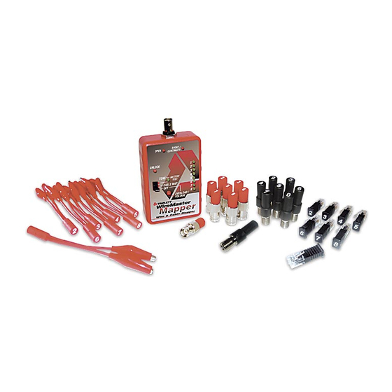
Page 18: Included Items
8. Included Items The following items are included with the WireMaster Mapper Description Part Number BNC Remote 1 …………………………… 3274-1 BNC Remote 2 …………………………… 3274-2 BNC Remote 3 …………………………… 3274-3 BNC Remote 4 …………………………… 3274-4 BNC Remote 5 …………………………… 3274-5 BNC Remote 6 ……………………………... - Page 19 Description Part Number RJ11 / RJ45 Remote 1 …………………… RMT-RJ/M-1 RJ11 / RJ45 Remote 2 …………………… RMT-RJ/M-2 RJ11 / RJ45 Remote 3 …………………… RMT-RJ/M-3 RJ11 / RJ45 Remote 4 …………………… RMT-RJ/M-4 RJ11 / RJ45 Remote 5 …………………… RMT-RJ/M-5 RJ11 / RJ45 Remote 6 …………………… RMT-RJ/M-6 RJ11 / RJ45 Remote 7 ……………………...
- Page 20 Also Available BNC Remotes 1-8 ………………………... 3274-9 F Remotes 1-8 ……………………..…… RMT-F/F-9 RJ11 / RJ45 Remotes 1-8 ……..……….. RMT-RJ/M-9 Clip Lead Remotes 1-8 ……………..…..RMT-CLIP-9 Test Equipment Depot - 800.517.8431 99 Washington Street, Melrose, MA 02176 TestEquipmentDepot.com...
Need help?
Do you have a question about the WireMaster Mapper and is the answer not in the manual?
Questions and answers