Table of Contents
Advertisement
Western Products, PO Box 245038, Milwaukee, WI 53224‑9538 • www.westernplows.com
January 1, 2017
Lit. No. 99762, Rev. 02
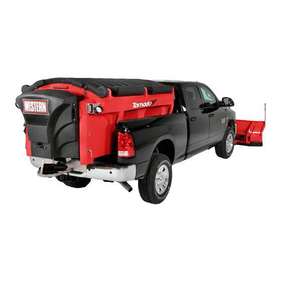
Tornado™ Hopper Spreader
#78000‑1, 78003‑1, 78006‑1
Owner's Manual
Original Instructions
CAUTION
Read this document before operating
or servicing the spreader.
This manual is for WESTERN
Tornado Hopper Spreaders with serial numbers
®
beginning with 160201 through 160902.
This manual supersedes all editions with an earlier date.
Advertisement
Table of Contents

Related Manuals for Western Tornado 78000-1


Summary of Contents for Western Tornado 78000-1
- Page 1 Western Products, PO Box 245038, Milwaukee, WI 53224‑9538 • www.westernplows.com January 1, 2017 Lit. No. 99762, Rev. 02 Tornado™ Hopper Spreader #78000‑1, 78003‑1, 78006‑1 Owner's Manual Original Instructions CAUTION Read this document before operating or servicing the spreader. This manual is for WESTERN Tornado Hopper Spreaders with serial numbers ®...
-
Page 3: Table Of Contents
TABLE OF CONTENTS PREFACE ..............4 Controlling Material Application ......15 Owner's Information ..........4 BLAST/Maximum Application ......15 SAFETY ..............5 Cab Control Modes ..........15 Safety Definitions ..........5 Ready Mode ............15 Warning/Caution Labels ........5 ON Mode............. 15 Serial Number Label .......... -
Page 4: Preface
PREFACE This manual has been prepared to acquaint you with When service is necessary, bring your hopper the safety information, operation and maintenance of spreader to your distributor. They know your spreader your new hopper spreader. Please read this manual best and are interested in your complete satisfaction. -
Page 5: Safety
SAFETY SAFETY DEFINITIONS WARNING/CAUTION LABELS Become familiar with and inform users about the WARNING warning and caution labels on the spreader. Indicates a potentially hazardous situation that, if not avoided, could result in death or NOTE: If labels are missing or cannot be read, see serious personal injury. -
Page 6: Serial Number Label
SAFETY SERIAL NUMBER LABEL SAFETY PRECAUTIONS Improper installation and operation could cause personal injury and/or equipment and property damage. Read and understand labels and the Owner's Manual before installing, operating, or making adjustments. WARNING • Driver to keep bystanders minimum of 25 feet away from operating spreader. -
Page 7: Fuses
SAFETY PERSONAL SAFETY CAUTION • Do not operate a spreader in need of • Remove ignition key and put the vehicle in park or maintenance. in gear to prevent others from starting the vehicle • Before operating the spreader, reassemble during installation or service. -
Page 8: Ventilation
SAFETY VENTILATION TORQUE CHART WARNING CAUTION Vehicle exhaust contains lethal fumes. Read instructions before assembling. Breathing these fumes, even in low Fasteners should be finger tight until concentrations, can cause death. Never instructed to tighten according to the Torque operate a vehicle in an enclosed area without Chart. -
Page 9: Loading
LOADING This Owner's Manual covers vehicles that have been CAUTION recommended for carrying the hopper spreader. Please Read and adhere to manufacturer's see your local dealer for proper vehicle applications. ice‑control material package labeling, including Material Safety CERTIFICATION Data Sheet requirements. WARNING MATERIAL WEIGHTS New untitled vehicle installation of a spreader... -
Page 10: Spreader Specifications
LOADING SPREADER SPECIFICATIONS Overall Empty Capacity Overall Overall Spreader Recommended Length Weight Struck Width Height Description (in) (lb) (cu yd) (in) (in) Regular Capacity 3/4–1 ton Pickup 7' Hopper Body Trucks above Double‑Wall Poly 8500 lb GVWR 8' Hopper Body 3/4–1 ton Pickup w/o Collar Trucks above... -
Page 11: Determining Vehicle Payload Worksheet
LOADING Determining Vehicle Payload Worksheet Example: Material Type Dry Salt Equipment installed when 7' Poly Hopper vehicle was weighed Spreader Front Gross Axle Weight Rating (FGAWR) (lb) Rear Gross Axle Weight Rating (RGAWR) (lb) Gross Vehicle Weight Rating 8600 (GVWR) (lb) Gross Vehicle Weight (empty) –... -
Page 12: Mounting The Spreader
MOUNTING THE SPREADER 4. The spreader can be moved into the truck bed NOTE: Periodically throughout the snow and ice either by lifting the spreader by the four molded-in control season, verify that mounting devices handles located on the corner legs or by sliding are secure. - Page 13 MOUNTING THE SPREADER Tip the spreader toward the truck until the sill rests WARNING on the rear edge of the truck bed. Spreader shall be bolted to vehicle frame. Do not rely on the tie‑down chains or straps 8. Lift the rear of the spreader and slide it into the alone to hold spreader in vehicle.
-
Page 14: Operating The Spreader - Cab Control
OPERATING THE SPREADER – CAB CONTROL STARTING AND STOPPING SPREADER WARNING Never operate equipment when under the WARNING influence of alcohol, drugs, or medications that Before starting the spreader, the driver shall might alter your judgment and/or reaction time. verify that all bystanders are a minimum of 25 feet away from operating spreader. -
Page 15: Controlling Material Application
OPERATING THE SPREADER – CAB CONTROL CONTROLLING MATERIAL APPLICATION CAB CONTROL MODES The material application settings can be adjusted Ready Mode while spreader is ON or OFF. Settings are shown by the indicator lights around the control knobs. When Vehicle ignition is set to ACC or ON; cab control is OFF. the spreader is OFF, a single LED will light to show the Control has power. -
Page 16: Cab Control Codes - Table
OPERATING THE SPREADER – CAB CONTROL CAB CONTROL CODES Setup Codes Code Definition Procedure Calibrate the Empty Hopper setting. With control in ON mode, press and hold the left control knob until the Cb code displays. Calibration cycle is automatic.* Clear calibration data for Empty Hopper Press the right control knob to clear all calibration data during the setting;... - Page 17 OPERATING THE SPREADER – CAB CONTROL Cab Control Codes, continued Error Codes – Spreader Operation Stopped Code Definition Possible Cause Suggested Solution Bad button. Button is stuck. Inspect control. Free up button. Button was pressed while Do not press any spreader cab control buttons vehicle ignition was entering while the vehicle ignition is being engaged.
-
Page 18: Setup Procedures
OPERATING THE SPREADER – CAB CONTROL SETUP PROCEDURES Adjust LED Brightness Level (LS and SL Codes) Calibrate the Empty Hopper Setting (Cb and EH Codes) The brightness setting of the cab control lights can be adjusted from 1 to 16. The factory default setting is 8. Calibrating the empty hopper setting enables the cab 1. -
Page 19: Operating The Spreader
OPERATING THE SPREADER DUMP FUNCTION ACCESSORY WORK LIGHT The dump function allows the operator to activate Electric-powered spreaders are equipped with a the conveyor to empty the hopper after use or load button to operate an accessory work light. The button material into a walk-behind spreader. -
Page 20: Removing The Spreader
REMOVING THE SPREADER 5. To remove the spreader without a lifting device, CAUTION two or more people are recommended. Move Before lifting, verify that hopper is empty of spreader rearward until it balances at the rear of material. The lifting device must be able to the bed. -
Page 21: Maintenance
MAINTENANCE CONVEYOR PINTLE CHAIN TENSION CAUTION Disconnect electric power at spreader 1. Periodically check the conveyor chain tension. electrical wiring harness connection and tag The spreader should be out of the vehicle. To out if required before servicing or performing check the tension, measure in 20"–24"... -
Page 22: Storage
MAINTENANCE STORAGE 4. Secure the spreader to the structure using chains or straps to ensure that it cannot tip or fall. The spreader can be stored on end (on its feet) for storage; however, steps must be taken to properly support it with blocks and secure it. -
Page 23: Electrical Components
ELECTRICAL COMPONENTS VEHICLE HARNESS DIAGRAM Cab Control 18 ga Red 4-Way Connector To Vehicle Switched Accessory To Vehicle CHMSL Signal (tap located in cab) Connectors 18 ga Shielded Twisted-Pair Cable 6 ga Red 100 Amp Fuse 4 ga Red 18 ga Black 4 ga Black To Vehicle CHMSL Signal (tap located in rear of vehicle) - Page 24 ELECTRICAL COMPONENTS Isolated Stud Block ACC Relay-Fuse Mounting Locations To Conveyor Motor Cable Assembly BLACK (–) BLACK Spinner Motor ORANGE BLACK BLACK ACC Taps WHITE Spreader Module To CHMSL Harness Assembly Conveyor Switches Cable Assembly To Spinner Motor Work Light Switch Harness Assembly Lit.
-
Page 25: Troubleshooting Guide
TROUBLESHOOTING GUIDE Please see your distributor for service. The Before servicing the spreader: troubleshooting reference table below may guide you • Review all safety information. in diagnosing the issue. • Confirm that all electrical connections are tight and clean. For a reference table of the cab control error codes, see the "Operating the Spreader –... - Page 26 TROUBLESHOOTING GUIDE Problem Possible Cause Suggested Solution Unplug the spreader harness and tag out, if required, before performing any of the following repairs. 1. Obstruction is preventing rotation. 1. Clear obstruction. 2. Gear box is damaged. 2. Replace gear box if output shaft does not turn when motor shaft turns.
- Page 28 Copyright © 2017 Douglas Dynamics, LLC. All rights reserved. This material may not be reproduced or copied, in whole or in part, in any printed, mechanical, electronic, film or other distribution and storage media, without the written consent of Western Products. Authorization to photocopy items for internal or personal use by Western Products outlets or spreader owner is granted.
Need help?
Do you have a question about the Tornado 78000-1 and is the answer not in the manual?
Questions and answers