Table of Contents
Advertisement
Quick Links
December 15, 2023
Lit. No. 32041EN, Rev. 00
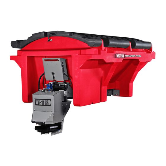
MARAUDER™ Hopper Spreaders
#P150A, P220A, P150C, P220C
Owner's Manual
Original Instructions
CAUTION
Read this document before operating
or servicing the spreader.
This manual is for MARAUDER poly hopper spreaders with serial numbers
beginning with 230605 and higher.
This manual supersedes all editions with an earlier date.
Advertisement
Table of Contents

Related Manuals for Western MARAUDER P150A


Summary of Contents for Western MARAUDER P150A
- Page 1 December 15, 2023 Lit. No. 32041EN, Rev. 00 MARAUDER™ Hopper Spreaders #P150A, P220A, P150C, P220C Owner's Manual Original Instructions CAUTION Read this document before operating or servicing the spreader. This manual is for MARAUDER poly hopper spreaders with serial numbers beginning with 230605 and higher.
-
Page 2: Owner's Information
PREFACE This manual has been prepared to acquaint you with When service is necessary, bring your hopper the safety information, operation, and maintenance of spreader to your distributor. They know your spreader your new hopper spreader. Please read this manual best and are interested in your complete satisfaction. -
Page 3: Table Of Contents
TABLE OF CONTENTS Safety................4 Operating the Spreader .......... 20 Safety Definitions ..........4 Cab Control ............20 Warning/Caution Labels ........4 Powering the Control ........20 Auger Units ............. 5 Starting and Stopping Spreader ....21 Chain Units ............. 6 Controlling Material Application .... -
Page 4: Safety
SAFETY SAFETY DEFINITIONS WARNING/CAUTION LABELS Become familiar with and inform users about the WARNING warning and caution labels on the spreader. Indicates a potentially hazardous situation that, if not avoided, could result in death or NOTE: If labels are missing or cannot be read, see serious personal injury. -
Page 5: Auger Units
SAFETY Auger Units Warning/Caution Label (both sides of hopper) Lit. No. 32041EN/32042EN/32043EN, Rev. 00 December 15, 2023... -
Page 6: Chain Units
SAFETY Chain Units Warning/Caution Label (both sides of hopper) Lit. No. 32041EN/32042EN/32043EN, Rev. 00 December 15, 2023... -
Page 7: Serial Number Label
SAFETY AUGER SERIAL NUMBER LABEL CHAIN SERIAL NUMBER LABEL Located on driver's side. Code Definition 2-Digit Year 2-Digit Month 2-Digit Day 2-Digit Location Code XXXX 4-Digit Sequential Number ZZZZZ 5- to 7-Digit Assembly PN Lit. No. 32041EN/32042EN/32043EN, Rev. 00 December 15, 2023... -
Page 8: Safety Precautions
SAFETY SAFETY PRECAUTIONS WARNING Vehicles <10,000 lb (4536 kg) GVWR: Improper installation and operation could cause Obstructing the visibility from the vehicle's personal injury and/or equipment and property rear camera could result in serious injury or damage. Read and understand labels and the damage. -
Page 9: Fuses
SAFETY FUSES CAUTION The electrical system contains several blade-style • Do not operate a spreader in need of automotive fuses. If a problem should occur and maintenance. fuse replacement is necessary, the replacement • Before operating the spreader, reassemble fuse must be of the same type and amperage any parts or hardware removed for cleaning rating as the original. -
Page 10: Cell Phones
SAFETY CELL PHONES NOISE A driver's first responsibility is the safe operation Airborne noise emission during use is below 70 dB(A) of the vehicle. The most important thing you can for the spreader operator. do to prevent a crash is to avoid distractions and pay attention to the road. -
Page 11: Loading
LOADING This Owner's Manual covers vehicles that have been CAUTION recommended for carrying the hopper spreader. Never use wet materials or materials with Please see your local dealer for proper vehicle foreign debris with any of these spreaders. applications. These units are designed to handle dry, clean, free-flowing material. -
Page 12: Load Volume
LOADING LOAD VOLUME DETERMINING VEHICLE PAYLOAD Load Volume (yd Hopper WARNING Model Overloading could result in an accident or P150 1.9 / 1.45 1.5 / 1.15 damage. Do not exceed GVWR or GAWR ratings as found on the driver-side door 2.7 / 2.06 2.2 / 1.68 P220... -
Page 13: Determining Vehicle Payload Worksheet
LOADING Determining Vehicle Payload Worksheet Example: Material Type Dry Salt P150C Equipment installed when Hopper vehicle was weighed Spreader Front Gross Axle Weight 6000 Rating [FGAWR] (lb) Rear Gross Axle Weight 7000 Rating [RGAWR] (lb) Gross Vehicle Weight 11,000 Rating [GVWR] (lb) Gross Vehicle Weight [GVW], –... -
Page 14: Mounting The Spreader
MOUNTING THE SPREADER INSTALL HOPPER IN TRUCK BED Auger NOTE: Periodically throughout the snow and ice control season, verify that mounting devices Sill are secure. Brackets CAUTION Before lifting, verify that the hopper is empty of material. The lifting device must be able to support the spreader's weight as shown in the spreader specifications table. - Page 15 MOUNTING THE SPREADER 4. The spreader can be moved into the truck bed 5. To lift the spreader into the truck bed from the either by lifting the spreader by all four of the ground, stand the spreader up on the feet at the molded-in tie-down points located along the sides rear of the spreader on top of two spacers at least of the spreader body or by sliding the spreader...
- Page 16 MOUNTING THE SPREADER 6. Position the spreader on its feet at the recomended distance from the rear of the truck as determined by the chart below. Loading Distance from Upright Chain or Auger Poly Hopper to Truck Bed (inches) for Bed Height (in)* Size P150 (7') P220 (8')
-
Page 17: Install Tie-Down Straps
MOUNTING THE SPREADER Construct and Install Sill Spacer 9. Adjust the spreader position to align the holes in the mounting bars with the mounting holes in the truck bed. If mounting holes are not already 1. Measure the distance from the hopper drive line drilled, refer to the hopper spreader Installation end to the front of the vehicle bed. -
Page 18: Chute Installation
CHUTE INSTALLATION CHUTE INSTALLATION Confirm/Adjust Chute Length Chute Configurations Ideal spinner height is 12"–18" (30 cm–46 cm) above the ground. For some installations the chute length may need to be adjusted to achieve the desired The chute comes in two lengths. spinner height. -
Page 19: Install Chute To Hopper
CHUTE INSTALLATION Install Chute to Hopper The chute can pivot on either pin to provide access to the feed area of the hopper. The chute is designed to swing open in one direction only. 1. Two people are recommended for this step. Pick It cannot be opened without disconnecting the up the chute from each side and slide the chute hopper harness cable. -
Page 20: Operating The Spreader
OPERATING THE SPREADER CAB CONTROL Powering the Control Power is not applied to the control until the vehicle WARNING ignition is turned to ACC or ON. Once the control Never operate equipment when under the has power it performs a light check and displays the influence of alcohol, drugs, or medications software version on the status display. -
Page 21: Starting And Stopping Spreader
OPERATING THE SPREADER Starting and Stopping Spreader Controlling Material Application The material application settings can be adjusted WARNING while spreader is ON or OFF. Settings are shown by Before starting the spreader, the driver shall the indicator lights around the control knobs. When verify that all bystanders are a minimum of the spreader is OFF, a single LED will light to show the 25 feet (7.62 m) away from operating spreader. -
Page 22: Cab Control Modes
OPERATING THE SPREADER Cab Control Modes Error Mode When an error condition occurs, spreader operation will shut down. A two-character error code will flash on the display and a beep will sound. If there are Vehicle ignition is set to ACC or ON; cab control is multiple error codes, the codes will flash in a repeating OFF. -
Page 23: Cab Control Codes
OPERATING THE SPREADER Cab Control Codes Setup Codes Code Definition Procedure Calibrate the Empty Hopper setting. With control in ON mode, press and hold the left control knob until the Cb code displays. Calibration cycle is automatic.* Clear calibration data for Empty Hopper Press the right control knob to clear all calibration data during the setting;... - Page 24 OPERATING THE SPREADER Error Codes – Spreader Operation Stopped Code Definition Possible Cause Suggested Solution Bad button. Button is stuck. Inspect control. Free up button. Button was pressed while Do not press any spreader cab control buttons vehicle ignition was entering while the vehicle ignition is being engaged.
-
Page 25: Error Codes
OPERATING THE SPREADER Error Codes continued Error Codes – Spreader Operation Stopped Code Definition Possible Cause Suggested Solution Low battery. Hopper Bad connection or low battery. Voltage is measured at the hopper module, so module is sensing ≤ 6V. Snowplow or other vehicle Lb code may indicate cable voltage loss. -
Page 26: Setup Procedures
OPERATING THE SPREADER Setup Procedures Clearing Empty Hopper Calibration Data (Cc Code) The empty hopper calibration may be cleared, if Calibrate the Empty Hopper Setting desired. The control will no longer display the EH (Cb and EH Codes) status code when the hopper is empty. Calibrating the empty hopper setting enables the cab Start the calibration cycle as described above. -
Page 27: Adjust Led Brightness Level (Ls And Sl Codes)
OPERATING THE SPREADER Adjust LED Brightness Level (LS and SL Codes) The brightness setting of the cab control lights can be adjusted from 1 to 16. The factory default setting is 8. 1. Turn the vehicle ignition to ACC or ON. If necessary, press the cab control ON/OFF button to turn the control OFF. -
Page 28: Spread Pattern Adjustment
OPERATING THE SPREADER SPREAD PATTERN ADJUSTMENT • Handle in the left and center-left notches: Material is directed to the left (driver's) side of the vehicle. The spread pattern and amount of material dispensed • Handle in the center notch: Material is directed depend on hopper drive speed and shutter deflector evenly to both sides of the vehicle. -
Page 29: Material Spread Patterns
OPERATING THE SPREADER Material Spread Patterns Handle in Center Notch Handle in Handle in Center-Left Notch Center-Right Notch Handle in Left Handle in Right (driver-side) Notch (curb-side) Notch Lit. No. 32041EN/32042EN/32043EN, Rev. 00 December 15, 2023... -
Page 30: Dump Function
OPERATING THE SPREADER DUMP FUNCTION ACCESSORY WORK LIGHT The dump function allows the operator to activate the The spreader is equipped with a button to operate an material feed buttons to empty the hopper after use or accessory work light. The button is on the driver's side load material into a walk-behind spreader. -
Page 31: Removing The Spreader
REMOVING THE SPREADER REMOVING THE SPREADER CAUTION Before lifting, verify that hopper is empty of material. The lifting device must be able to support the spreader's weight as shown in the spreader specifications table. 1. The spreader can be removed from the truck bed either by lifting the spreader by the four molded- in tie-down points located along the sides of the spreader body or by sliding the spreader out of the... -
Page 32: Maintenance
MAINTENANCE CAUTION Disconnect electric power at spreader electrical wiring harness connection and tag out if required before servicing or performing maintenance. GREASE FITTINGS To keep your spreader running smoothly, lubricate the grease fittings as shown after each use and at the end of each season. -
Page 33: Conveyor Pintle Chain Tension
MAINTENANCE CONVEYOR PINTLE CHAIN TENSION 2. Loosen the jam nut on one of the idler take-up bolts. Tighten the take-up bolt by turning it clockwise while holding the jam nut. Repeat with Periodically check the conveyor chain tension. the opposite take-up bolt, tightening equally on This procedure is most easily performed when the both passenger's side and driver's side until the spreader is outside of the vehicle. -
Page 34: Removing The Chute
MAINTENANCE REMOVING THE CHUTE AFTER EACH USE If the chute must be removed for repair or CAUTION maintenance: DO NOT leave unused material in hopper. Material can freeze or solidify, causing unit to not 1. Unplug the chute motor plug from the hopper body work properly. -
Page 35: Storage
MAINTENANCE STORAGE 3. Add blocks supporting the sides of the hopper body and power group, as shown below and on page 36. CAUTION 4. Secure the spreader to the structure using chains Before lifting, verify that the hopper is empty or straps to ensure that it cannot tip or fall. -
Page 36: Fuse Replacement
MAINTENANCE Auger Bottom View - Upright Position Chain Bottom View - Upright Position Support Block Support Block FUSE REPLACEMENT If a problem should occur and fuse replacement is necessary, the replacement fuse must be of the same type and amperage rating as the original. Installing a fuse with a higher rating can damage the system and could start a fire. -
Page 37: Electrical Components
ELECTRICAL COMPONENTS VEHICLE HARNESS DIAGRAM Cab Control 4-Way Connector 18 ga Red To Vehicle Switched Accessory Vehicle Control Harness To Vehicle CHMSL Signal (tap located in cab) Connectors 18 ga Shielded Twisted-Pair Cable 6 ga Red 100A Fuse 4 ga Red 18 ga Black Vehicle 4 ga Black... -
Page 38: Electrical Control Box Diagram
ELECTRICAL COMPONENTS ELECTRICAL CONTROL BOX DIAGRAM Auger Units Conveyor Switch Acc. Connection Block Acc. Work Light Switch Motor Harness Chute Harness Plate Light Main Harness CHMSL Acc Taps (Orange & Black) Blue – Vibrator Orange – Prewet White – Strobe Gray –... -
Page 39: Chain Units
ELECTRICAL COMPONENTS Chain Units Conveyor Switch Acc. Connection Block Acc. Work Light Switch Motor Harness Chute Harness Plate Light Main Harness CHMSL Acc Taps (Orange & Black) Blue – Vibrator Orange – Prewet White – Strobe Gray – Work Light Conveyor Switch Lit. -
Page 40: Troubleshooting Guide
TROUBLESHOOTING GUIDE Please see your distributor for service. The Before servicing the spreader: troubleshooting reference table below may guide you • Review all safety information. in diagnosing the issue. • Confirm that all electrical connections are tight and clean. For a reference table of the cab control error codes, see the "Operating the Spreader –... - Page 41 TROUBLESHOOTING GUIDE Problem Possible Cause Suggested Solution Unplug the spreader harness and tag out, if required, Spinner does not turn. before performing any of the following repairs. Motor is running. 1. Obstruction is preventing rotation. 1. Clear obstruction. Unplug the spreader harness and tag out, if required, before performing any of the following repairs.
- Page 42 Western Products outlets or spreader owner is granted. Western Products reserves the right under its product improvement policy to change construction or design details and furnish equipment when so altered without reference to illustrations or specifications used. Western Products or the vehicle manufacturer may require or recommend optional equipment for spreaders.
Need help?
Do you have a question about the MARAUDER P150A and is the answer not in the manual?
Questions and answers