Table of Contents
Advertisement
October 1, 2018
Lit. No. 94430, Rev. 09
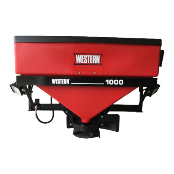
Low-Profi le Tailgate Spreader
68800, 67440
Model 1000 & 2000
Owner's Manual
Original Instructions
CAUTION
Read this manual before installing or
operating the spreader.
This manual is for WESTERN
Model 1000 & 2000 Low-Profi le Tailgate Spreaders
®
with serial numbers 10003 and higher (Model 1000) and 20364 and higher (Model 2000).
This manual supersedes all editions with an earlier date.
Advertisement
Table of Contents

Related Manuals for Western 1000


Summary of Contents for Western 1000
- Page 1 This manual is for WESTERN Model 1000 & 2000 Low-Profi le Tailgate Spreaders ® with serial numbers 10003 and higher (Model 1000) and 20364 and higher (Model 2000). This manual supersedes all editions with an earlier date.
-
Page 3: Table Of Contents
TABLE OF CONTENTS PREFACE ..............4 OPERATING THE SPREADER ........ 13 Owner's Information Form ........4 Driving and Spreading on Snow and Ice .... 13 SAFETY ..............5 Controls ............... 14 Safety Defi nitions ..........5 Variable Speed (PWM) Control – New Style ..14 Warning/Caution Labels ........ -
Page 4: Preface
PREFACE This manual has been prepared to acquaint you with When service is necessary, bring your spreader to the safety information, operation, and maintenance of your local dealer. They know your spreader best and your new spreader. Please read this manual carefully are interested in your complete satisfaction. -
Page 5: Safety
SAFETY SAFETY DEFINITIONS WARNING/CAUTION LABELS Please become familiar with and inform users about WARNING the warning and caution labels on the spreader. Indicates a potentially hazardous situation that, if not avoided, could result in death or NOTE: If labels are missing or cannot be read, see serious personal injury. -
Page 6: Serial Number Label
SAFETY SERIAL NUMBER LABEL SAFETY PRECAUTIONS Improper installation and operation could cause personal injury and/or equipment and property damage. Read and understand labels and this Owner's Manual before installing, operating, or making adjustments. WARNING • Driver to keep bystanders minimum of 25 feet away from operating spreader. -
Page 7: Fuses
SAFETY PERSONAL SAFETY CAUTION During the hopper installation we recommend • Remove ignition key and put the vehicle in PARK the addition of an OSHA compliant Backup or in gear to prevent others from starting the Alarm. This alarm is required for OSHA vehicle during installation or service. -
Page 8: Ventilation
SAFETY VENTILATION TORQUE CHART WARNING CAUTION Vehicle exhaust contains lethal fumes. Read instructions before assembling. Breathing these fumes, even in low Fasteners should be fi nger tight until concentrations, can cause death. Never instructed to tighten according to torque operate a vehicle in an enclosed area without chart. -
Page 9: Loading
NOTE: If spreader and ice control material loading is in doubt, weigh vehicle for compliance with vehicle ratings. Model 1000 Model 2000 8.0 ft 10.6 ft 5.9 ft 7.2 ft... -
Page 10: Mounting The Spreader
MOUNTING THE SPREADER RECEIVER MOUNT SPREADER 1. Attach the spreader to the receiver mount with six 3/8" x 1" cap screws. 2. Insert the assembled unit into the receiver hitch and secure with pin (not included). 3. Plug the spreader harness into the vehicle harness. -
Page 11: Fixed Mount Spreader
MOUNTING THE SPREADER FIXED MOUNT SPREADER 1. Install the left and right top brackets to the truck bed rail with two 1/2" cap screws, four 1/2" fl at washers, and two 1/2" locknuts per side. Secure the small mounting fl ange of each top bracket to the bed rail using two 5/16"... -
Page 12: Swing Away ® Spreader
MOUNTING THE SPREADER SWING AWAY SPREADER ® 1. Fasten the left and right top brackets along with any shims to the truck bed rail with two 1/2" cap screws, two 1/2" fl at washers, and two 1/2" locknuts per bracket. Install the two 5/16" cap screws and 5/16"... -
Page 13: Operating The Spreader
OPERATING THE SPREADER DRIVING AND SPREADING Here are some tips for driving in these conditions: ON SNOW AND ICE • Drive defensively. • Do not drink, then drive or spread ice-control CAUTION materials. Drinking and then driving or spreading is •... -
Page 14: Controls
OPERATING THE SPREADER CONTROLS Variable Speed (PWM) Control – New Style There are two control options. They include the ON/Maximum Diagnostic Variable Speed (PWM) Control and the ON/OFF Speed Button Indicator Light Control. Both have had design changes. Identify older and newer styles by the face plate diagrams below to fi... - Page 15 OPERATING THE SPREADER Adjusting the Spinner Speed NOTE: Always place the cover on the hopper to prevent moisture buildup. Do not let the spreader The speed setting can be adjusted when the spreader sit idle with material in the hopper for an extended is either ON or OFF.
-
Page 16: Variable Speed (Pwm) Control - Old Style
OPERATING THE SPREADER Variable Speed (PWM) Control – Old Style Adjusting the Spinner Speed The speed setting can be adjusted when the spreader is either ON or OFF. 1. Turn the speed dial clockwise. Speed will increase as the numbers on the speed dial increase. 2. -
Page 17: On/Off Control
OPERATING THE SPREADER ON/OFF Control Starting and Stopping the Motor New Style WARNING Before starting the spreader, the driver shall Spinner Indicator Light verify that all bystanders are a minimum of (when lit, indicates 25 feet away from operating spreader. power to the motor) 1. -
Page 18: Removing The Spreader
REMOVING THE SPREADER FIXED MOUNT CAUTION Empty the hopper before removing the Removing the Spreader spreader. 1. Unplug the spreader and CHMSL (if equipped). CAUTION 2. Remove the two 3/8" cap screws, washers, and During removal or mounting, securely grip locknuts that fasten the spreader to the bumper of spreader to avoid dropping. -
Page 19: Swing Away Mount
REMOVING THE SPREADER SWING AWAY MOUNT Removing the Base Plates ® 1. Remove the four 3/8" cap screws, washers, Removing the Spreader locknuts, and any shims that fasten the base plate to the bumper. 1. Unplug the spreader and CHMSL (if equipped). 2. -
Page 20: Maintenance
MAINTENANCE 4. If bearings pass inspection, be sure to CAUTION thoroughly grease them with a good quality Disconnect electric power at spreader multipurpose grease. See "Bearing and Set Screw electrical wiring harness connection and tag Maintenance" in this section. out if required before servicing or performing maintenance. -
Page 21: Postseason Maintenance
MAINTENANCE POSTSEASON MAINTENANCE DRIVE BELT REPLACEMENT CAUTION CAUTION Disconnect electric power at spreader Disconnect electric power at spreader electrical wiring harness connection and tag electrical wiring harness connection and tag out if required before servicing or performing out if required before servicing or performing maintenance. -
Page 22: Bearing And Set Screw Maintenance
MAINTENANCE BEARING AND SET SCREW FUSE REPLACEMENT MAINTENANCE See the harness wiring diagrams on the following pages for fuse ratings and locations. Disconnect the electrical plug between the spreader and the truck before performing any maintenance. If a problem should occur and fuse replacement is necessary, the replacement fuse must be of the same 1. -
Page 23: 4-Pin Harness Wiring Diagram
4-PIN HARNESS WIRING DIAGRAM – LOW-PROFILE SPREADERS Cab Control White Connector Two-Way Molded Connector Red Connector 6A Fuse 14 ga Red 8 ga Red To vehicle ignition 8 ga Red (accessory wire or fuse box) 30A Fuse 10 ga Red 14 ga Black 8 ga Black 14 ga Yellow... -
Page 24: 2-Pin Harness Wiring Diagram
2-PIN HARNESS WIRING DIAGRAM – LOW-PROFILE SPREADERS Old Style New Style (no adapter required) (adapter required) CHMSL Speed Speed Control Control Black White White Black Black Adapter White Vehicle Black Stoplight Harness Fuse Fuse holder Butt White Connector Black Power Lead Battery Harness Black... -
Page 25: Troubleshooting Guide
TROUBLESHOOTING GUIDE For control operation and use of diagnostic indicator lights, locate the section for your control style in the Operating the Spreader section of this manual. Problem Possible Cause Suggested Solution 1. Control connector plug is loose. 1. Check plug connection at cab control. 2. - Page 26 TROUBLESHOOTING GUIDE Problem Possible Cause Suggested Solution Unplug the spreader harness and tag out, if required, before performing any of the following repairs. 1. Obstruction is preventing rotation. 1. Clear obstruction. 2. Drive belt is loose or damaged. 2. Adjust tension or replace belt if worn or damaged.
- Page 28 Western Products reserves the right under its product improvement policy to change construction or design details and furnish equipment when so altered without reference to illustrations or specifi cations used. Western Products or the vehicle manufacturer may require or recommend optional equipment for spreaders. Do not exceed vehicle ratings with a spreader. Western Products offers a limited warranty for all spreaders and accessories.
Need help?
Do you have a question about the 1000 and is the answer not in the manual?
Questions and answers