Jungheinrich EFG 110k Operating Instructions Manual
Hide thumbs
Also See for EFG 110k:
- Operating instructions manual (103 pages) ,
- Operating instructions manual (6 pages)

Related Manuals for Jungheinrich EFG 110k


Summary of Contents for Jungheinrich EFG 110k
- Page 1 EFG 110-115 10.09 Operating instructions en-GB 51151449 10.20 EFG 110k EFG 110 EFG 113 EFG 115...
- Page 3 Declaration of Conformity Manufacturer Jungheinrich AG, 22039 Hamburg, Germany Description Industrial truck Type Option Serial no. Year of manufacture EFG 110k EFG 110 EFG 113 EFG 115 On behalf of Date EU DECLARATION OF CONFORMITY The undersigned hereby declare that the powered truck described in detail complies with the current versions of European Directives 2006/42/EG (Machinery Directive) and 2014/30/EU (Electromagnetic Compatibility - EMC).
- Page 5 Foreword Notes on the operating instructions The present ORIGINAL OPERATING INSTRUCTIONS are designed to provide sufficient instruction for the safe operation of the industrial truck. The information is provided clearly and concisely. The chapters are arranged by letter and the pages are numbered continuously.
- Page 6 Copyright Copyright of these operating instructions remains with JUNGHEINRICH AG. Jungheinrich Aktiengesellschaft Friedrich-Ebert-Damm 129 22047 Hamburg - Germany Tel: +49 (0) 40/6948-0 www.jungheinrich.com...
-
Page 7: Table Of Contents
Contents Correct Use and Application General Correct application Approved application conditions Internal Operation in Cold Stores with Cold Store Equipment (o) Proprietor responsibilities Adding attachments and/or optional equipment Removal of components Truck Description Application Truck models and rated capacity Assemblies and Functional Description Travel direction definition Assembly Overview Functional Description... - Page 8 Potential hazards Touch voltage hazard Safety Regulations for Handling Lead-Acid Batteries Battery types Battery dimensions Exposing the battery Battery removal and installation Charging the battery Charging the battery with a stationary charger Closing the battery cover Operation Safety Regulations for the Operation of Forklift Trucks Displays and Controls Control panel with display unit Side compartment control panel switch (o)
- Page 9 Camera system 6.10 Control layout “N” 6.11 Floor-Spot Troubleshooting Troubleshooting Operating the truck without its own drive system Emergency lowering Industrial Truck Maintenance Spare Parts Operational Safety and Environmental Protection Maintenance Safety Regulations Consumables and used parts Wheels Attachment Repairs and Inspection Lift Chains Hydraulic system Lubricants and Lubrication Schedule...
-
Page 11: A Correct Use And Application
A Correct Use and Application General The truck must be used, operated and serviced in accordance with the present instructions. All other types of use are beyond its scope of application and may result in damage to personnel, the industrial truck or property. Correct application NOTICE The maximum load and load distance are indicated on the capacity plate and must... - Page 12 The following operations are in accordance with regulations and are permitted: – Lifting and lowering of loads. – Stacking and retrieving loads – Transporting lowered loads over short distances. – The mast must be tilted back when transporting loads that are not secured against slipping and falling.
-
Page 13: Approved Application Conditions
Approved application conditions WARNING! Do not exceed the permissible surface and point loading limits on the travel paths. A second person is required as a lookout at blind spots. The operator must ensure that the loading ramp/dock cannot move or come loose during loading/unloading. -
Page 14: Proprietor Responsibilities
Proprietor responsibilities For the purposes of the present operating instructions the “operating company” is defined as any natural or legal person who either uses the industrial truck himself, or on whose behalf it is used. In special cases (e.g. leasing or renting) the proprietor is considered the person who, in accordance with existing contractual agreements between the owner and user of the industrial truck, is charged with operational duties. -
Page 15: B Truck Description
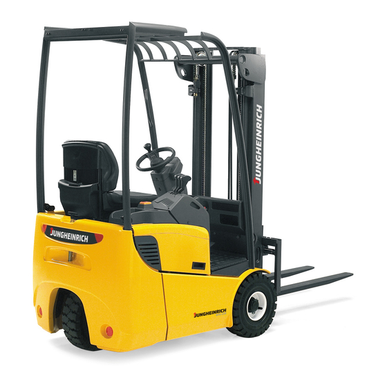
B Truck Description Application The EFG 110 - 115 is a three-wheel electric sit-down forklift truck. It is a cantilever counterbalanced truck which can lift, transport and deposit loads using the load handler attached in front. Closed bottom pallets can also be lifted. Truck models and rated capacity The rated capacity depends on the model. -
Page 16: Assemblies And Functional Description
Assemblies and Functional Description Travel direction definition The following determinations have been made for travel direction specification: The following conventions have been agreed for travel direction specification: Item Travel direction Left Reverse Forward Right... -
Page 17: Assembly Overview
Assembly Overview Item Component Driver's seat Overhead guard Mast Steering wheel Control and display unit Lifting mechanism control Emergency Disconnect switch Forks Fork carriage Battery cover Drive Trailer coupling Counterweight Standard equipment... -
Page 18: Functional Description
Functional Description Chassis The chassis, in conjunction with the counterweight, forms the supporting base structure of the truck. It is used to support the main components. Operator position and overhead guard The overhead guard comes in a range of models and protects the operator from falling objects and other external influences. - Page 19 Drive system The entire drive unit is enclosed in the counterweight. The steered rear wheel is also the drive wheel. A fixed, low-noise three-phase motor is driven via a transmission. The electronic traction controller ensures the smooth rotation of the drive motor and as a result consistently smooth travel, powerful acceleration and electrically controlled braking with energy recovery.
-
Page 20: Technical Specifications
Technical Specifications All technical details refer to standard trucks. Values indicated with *) may vary, depending on the types of equipment used (e.g. mast, cabin, tyres etc.). The technical specifications comply with the German "Industrial Truck Data Sheet" Guidelines. Technical modifications and additions reserved. Load centre distance The load centre distance D of the load handler is specified as the horizontal distance from the front face and the vertical distance from the upper edge of the load handler. -
Page 21: Performance Data
Performance data Model EFG 110k EFG 110 EFG 113 EFG 115 Q Rated capacity (where 1000 1000 1250 1500 C = 500 mm) C Load centre distance Travel speed, w. / 12/12.5 12/12.5 12/12.5 12/12.5 km/h w.o. load *) Lift speed, with / 0.28/0.50... -
Page 22: Dimensions
Dimensions Description EFG 110k EFG 110 EFG 113 EFG 115 a/2 Safety distance Mast height retracted *) 2000 2000 2000 2000 Free lift *) Lift *) 3000 3000 3000 3000 Mast height extended *) 3550 3550 3550 3550 Overhead guard height... -
Page 24: Weights
Weights All dimensions in kg. Model EFG 110k EFG 110 EFG 113 EFG 115 Net weight *) 2490 2570 2760 2870 (including battery) Front axle load (without lifting 1095 1145 1235 1270 load) *) Front axle load (with lifting load) -
Page 25: Tyre Type
Tyre type WARNING! The use of tyres that do not match the manufacturer's specifications can result in accidents. The quality of tyres affects the stability and performance of the truck. Uneven wear affects the truck's stability and increases the stopping distance. uWhen replacing tyres make sure the truck is not skewed. -
Page 26: Engine Data
Engine Data Designation EFG110-115 Drive motor 4 kW Lift motor 6 kW Designation EFG 110k EFG 110 EFG 113 EFG 115 Energy consumption 2.6 kWh/h 2.7 kWh/h according to EN cycle CO2 equivalent 1.40 kg/h 1.46 kg/h according to EN 16796... -
Page 27: En Norms
EN norms Noise emission level – EFG 110-115: 63 dB(A) *+/- 3 dB(A) depending on the truck's equipment in accordance with 12053 as harmonised with ISO 4871. The noise emission level is calculated in accordance with standard procedures and takes into account the noise level when travelling, lifting and when idle. The noise level is measured at the level of the driver's ear. -
Page 28: Conditions Of Use
Conditions of use Ambient temperature – operating at -20°C to 40°C Special equipment and authorisation are required if the truck is to be used continually in conditions of extreme temperature or condensing air humidity fluctuations. Electrical Requirements The manufacturer certifies compliance with the requirements for the design and manufacture of electrical equipment, according to EN 1175 "Industrial Truck Safety - Electrical Requirements", provided the truck is used according to its purpose. -
Page 29: Specifications According To Red Guideline (Radio Equipment Directive) For Radio Units
3.10 Specifications according to RED guideline (Radio Equipment Directive) for radio units The table contains any components installed according to the European Directive 2014/53/EU. The table shows the affected frequency range and the emitted transmission power for each component. Component Frequency range Transmission power Radio module (ISM Online) -
Page 30: Identification Points And Data Plates
Identification points and data plates Indication Points Warnings and notices such as capacity charts, strap points and data plates must be legible at all times. Replace if necessary. (mm) Q (kg) D (mm) Item Description Capacity (or reduced capacity) Wear seat belt Do not travel with a raised load or operate the mast forward tilt with a raised load Tipover warning... - Page 31 Item Description Attachment points for loading by crane Do not step onto or beneath the load: risk of trapping with moving mast Serial number, on chassis below the battery panel Warning: optical radiation (Floor-Spot) Max. body size Inspection plaque (o) Data plate Jacking points Model description...
-
Page 32: Data Plate
Data plate The illustration shows the standard version for EU member states. The data plate may differ in other countries. Item Model Item Model Rated capacity (kg) Load centre distance (mm) Battery voltage (V) Drive output Net weight w.o. battery (kg) Min./max. -
Page 33: Truck Capacity Plate
Truck capacity plate CAUTION! Accident risk from fork replacement If you replace the forks with ones that differ from the originals, the capacity will change. uWhen replacing the forks you must attach an additional capacity plate to the truck. uTrucks supplied without forks are given a capacity plate for standard forks (length: 1150 mm). - Page 34 Example of how to calculate the maximum capacity With a load centre distance (D) of 600 mm and a maximum lift height of (h ) 3600 mm the max. capacity (Q) is 1105 kg. Lift height limits The arrow shaped markings (45 and 46) on the inner and outer masts show the operator when the prescribed lift limits have been reached.
-
Page 35: Attachment Capacity Plate
Attachment capacity plate The attachment capacity plate is next to the truck capacity plate and gives the truck capacity Q (in kg) in conjunction with the attachment and the specified fork arms (t) (47) and where applicable fork extensions (o) (48). The model name and/or serial number for the attachment indicated on the attachment capacity plate must match the data plate of the attachment. -
Page 36: Stability
WARNING! Risk of accident from offset load centre of gravity The capacity of the truck is reduced when using side shifts that are more than 100 mm outside the truck centre. uNote the capacity plate with the reduced capacity. The capacity plate of the attachment with more than 100 mm possible side shift for a current clear offset working position with 100 mm side shift pushed out (50) is affixed separately to the other capacity plates. -
Page 37: Wind Loads
Wind loads Wind forces can affect the stability of a truck when lifting, lowering and transporting loads with large surface areas. Light loads must be especially secured when they are subjected to wind forces. This will prevent the load from sliding or falling. Stop the truck in both cases. -
Page 39: C Transport And Commissioning
C Transport and Commissioning Transport Transport can be carried out in two different ways, depending on the height of the mast and the local conditions. – Vertically, with the mast assembled (for low heights) – Vertically, with the mast dismantled (for large heights), all mechanical connections and hydraulic lines between the basic truck and the mast separated. -
Page 40: Lifting The Truck By Crane
Lifting the truck by crane WARNING! All persons involved in loading by crane must be trained Incorrect crane loading procedures due to untrained personnel can cause the truck to fall. There is a risk of injury to personnel and a risk of material damage to the truck. - Page 41 Lifting the truck by crane Requirements – Park the truck securely, see page 88. Procedure • Secure the crane slings to the attachment points (51) and (52. • Raise and load the truck. • Lower and deposit the truck carefully (see page 88).
-
Page 42: Loading With Another Industrial Truck
Loading with another industrial truck WARNING! The truck can be damaged The truck to be loaded can be damaged when loading with another industrial truck. uOnly trained specialist personnel should load the truck. uUse only trucks with sufficient capacity for loading. uOnly for loading and unloading. -
Page 43: Securing The Truck During Transport
Securing the truck during transport WARNING! Accidental movement during transport Improper fastening of the truck and mast during transport can result in serious accidents. uLoading must only be performed by specialist personnel trained for this purpose. The specialist personnel must be instructed in securing loads on road vehicles and handling load securing devices. - Page 44 Securing the industrial truck for transport Requirements – Position industrial truck securely on a lorry or trailer, see page 88. Tools and Material Required – 2 fastening belts with a tensioner – Retaining wedges. Procedure • Secure the truck with the fastening belt (53) at the top cross member of the mast (3) and the trailer...
-
Page 45: Using The Truck For The First Time
Using the Truck for the First Time Safety instructions for assembly and commissioning WARNING! Incorrect assembly can result in accidents The assembly of the truck at the application site, commissioning and operator training must only be performed by the manufacturer's customer service representatives who have been specially trained for these tasks. -
Page 47: D Battery - Servicing, Recharging, Replacement
D Battery - Servicing, Recharging, Replacement General notes on handling batteries Maintenance personnel Batteries may only be charged, serviced or replaced by trained personnel. These operating instructions and the manufacturer’s instructions concerning batteries and charging stations must be observed when carrying out the work. Park the truck securely before carrying out any work on the batteries (see page 88). -
Page 48: Touch Voltage Hazard
Touch voltage hazard WARNING! Hazardous contact voltages only arise in the event of a technical or physical defect. The batteries are normally charged. There is still some residual voltage in a discharged battery. This must be considered as a hazardous contact voltage. With this kind of defect the battery must not be touched and must not come into contact with metal objects see page 47. -
Page 49: Safety Regulations For Handling Lead-Acid Batteries
Safety Regulations for Handling Lead-Acid Batteries WARNING! Batteries can be hazardous Batteries contain an acid solution which is poisonous and corrosive. Avoid contact with battery acid at all times. uDispose of used battery acid in accordance with regulations. uAlways wear protective clothing and goggles when working with batteries. uDo not let battery acid come into contact with skin, clothing or eyes. -
Page 50: Battery Types
The truck will be equipped with different battery models, depending on the application. The following table shows which combinations are included as standard: Truck type Description Capacity EFG 110k 24 V - 4PzS 500 Ah EFG 110 24 V - 5PzS... -
Page 51: Exposing The Battery
Exposing the battery CAUTION! The drive motor operating temperature can cause injury When you open the battery cover the high operating temperature of the drive motor > 80° can result in injuries. uDo not touch the drive motor, and allow it to cool down. Exposing the battery with the SOLO-PILOT Requirements –... - Page 52 Exposing the battery with the MULTI-PILOT ( Requirements – Park the truck securely, see page 88. – Load handler lowered. – Key switch set to OFF. – Key removed. – Set the Emergency Disconnect OFF. Procedure • Release the steering column lock (58), push the steering column forward and secure it in this position.
-
Page 53: Battery Removal And Installation
Battery removal and installation WARNING! Accident risk during battery removal and installation Due to the battery weight and acid there is a risk of trapping or scalding when the battery is removed and installed. uNote the "Safety regulations for handling acid batteries" section in this chapter. uWear safety shoes when removing and installing the battery. - Page 54 Battery Removal and Installation Requirements – Park the truck securely, see page 88. – Battery exposed, see page 51. – Battery disconnected. Tools and Material Required – Crane lifting gear Procedure • Strap the crane lifting gear vertically over the recess in the overhead guard to the battery tray.
-
Page 55: Charging The Battery
Charging the battery WARNING! The gases produced during charging can cause explosions The battery produces a mixture of oxygen and hydrogen (electrolytic gas) during charging. Gassing is a chemical process. This gas mixture is highly explosive and must not be ignited. uSwitch the charging station and truck off first before connecting/disconnecting the charging cable of the battery charging station to/from the battery connector. - Page 56 The battery is now charged.
-
Page 57: Closing The Battery Cover
Closing the battery cover Closing the Battery Cover with the SOLO- PILOT Requirements – The battery cable is in the cable guide (61). Procedure • Close the battery cover with the driver's seat. • Move the cover (55) back until it engages. The battery cover is now closed. -
Page 59: Operation
E Operation Safety Regulations for the Operation of Forklift Trucks Driver authorisation The truck may only be used by suitably trained personnel, who have demonstrated to the proprietor or his representative that they can drive and handle loads and have been authorised to operate the truck by the proprietor or his representative. - Page 60 Hazardous area WARNING! Risk of accidents/injury in the hazardous area of the truck A hazardous area is defined as the area in which people are at risk due to travel or lifting operations of the truck, its load handler or the load. This also includes the area within reach of falling loads or lowering/falling operating equipment.
-
Page 61: Displays And Controls
Displays and Controls Item Control/display Function Parking-brake lever Applies/releases the parking brake. Control panel with Displays the battery capacity, service display unit hours, errors, key warning indicators, wheel position and travel direction. Steering wheel Steers the truck. soloPILOT Controls the following functions: –... - Page 62 Item Control/display Function Key switch Switches control current on and off. Removing the key prevents the truck from being switched on by unauthorised personnel. ISM access module Switches the truck on. Code lock Side storage-facility Switches electric options on and off control panel Brake pedal Provides infinitely variable braking control.
- Page 64 Item Control / Display Function Warning indicator for belt If the seat belt is not fastened, the warning lock control system indicator for the belt lock control system illuminates. Warning indicator for cab If the cab door is not closed, the warning door monitoring indicator for the cab door monitoring illuminates.
-
Page 66: Control Panel With Display Unit
Control panel with display unit The control panel display unit shows the operating data, the battery charge, the service hours and error details and information. Pictograms in the left top section of the control panel act as warning indicators. Item Control / Function Display Warning indicator... - Page 67 Item Control / Function Display Warning indicator – Monitors the temperature of the pump motor Pump motor, power and the power steering motor steering overtemperature – Performance is reduced if the temperature is excessive Seat switch warning Seat switch not closed indicator –...
-
Page 68: Side Compartment Control Panel Switch (O)
Side compartment control panel switch (o) Function Rear window heating Slow travel Beacon Seat heating Work lights Lift cutout override Windscreen washer system Instrument panel switches (o) Function Truck lighting... -
Page 69: Display
Display Item Function Hourmeter display Error display: – If an error (Err) or a warning (Inf) occurs, the error or info code is displayed. – If several errors occur they are displayed alternately at 1.5 second intervals. A warning is sounded. Battery capacity display –... - Page 70 2.4.1 Battery discharge indicator NOTICE Full discharge can damage the battery The standard setting for the battery discharge indicator is based on standard batteries. When using maintenance-free batteries (gel batteries), the display must be reset. uThis adjustment should only be made by the manufacturer’s customer service department.
-
Page 71: Preparing The Truck For Operation
Preparing the Truck for Operation Checks and operations to be performed before starting daily operation WARNING! Damage and other truck or attachment (optional equipment) defects can result in accidents. If damage or other truck or attachment (optional equipment) defects are discovered during the following checks, the truck must be taken out of service until it has been repaired. - Page 72 Checks before daily operation Procedure • Visually inspect the entire truck (in particular wheels, wheel bolts and load handler) for damage. • Check the fork stop (99) and fork retainer (100). • Visually inspect the hydraulic system in the visible area for damage and leaks.
- Page 73 • • • Visually inspect the battery attachment and cable connections. • Check the battery latch is present and working. • On trucks with lateral battery removal, check the left and right stops (101) in the battery compartment for damage. •...
-
Page 74: Entry And Exit
Entry and exit Requirements – Truck stationary. Procedure • Cab door open (if applicable). • To enter and exit the cab, hold onto the handle (102). Always face the truck when entering and exiting. Always use the entry aid (102) provided to climb onto the truck. An additional step is provided for the driver position extension (o). -
Page 75: Setting Up The Operator Position
Setting up the operator position WARNING! Accidents can occur if the driver's seat, steering column and armrest are not engaged The driver's seat, steering column and armrest can accidentally adjust during travel and therefore cannot be operated safely. uDo not adjust the driver’s seat, steering column or armrest while travelling. Procedure •... - Page 76 Setting the driver's weight NOTICE Incorrectly adjusted seat cushioning can damage your health To achieve optimal seat cushioning, the driver’s seat must be adjusted according to the driver’s weight. Set the driver's weight when the seat is occupied. uHold the weight adjustment lever only by the recess;...
- Page 77 Adjusting the seat position CAUTION! An unsecured driver's seat can cause injury An unsecured driver's seat can slide out of its guide during travel, resulting in accidents. uThe driver's seat must be locked in position. uDo not adjust the driver’s seat while travelling.
- Page 78 Adjusting the backrest extension CAUTION! Accident risk when adjusting the backrest during travel adjust backrest extension while travelling. Procedure • The backrest extension height can adjusted changing detent. • Pull the backrest up and lock it in place to extend the backrest. •...
- Page 79 Adjusting the lumbar support ( Procedure • Turn the hand wheel (109) to the required position. Position 0 = no warping in lumbar vertebrae area. Position 1 = increasing warping in upper lumbar vertebrae area. Position 2 = increasing warping in lower lumbar vertebrae area. The lumbar support is now adjusted.
-
Page 80: Restraint Systems
3.4.2 Adjusting the steering column Adjusting the steering column Procedure • Release the steering column stop (58). • Set the steering column to the required position (height and angle). • Fix the steering column stop (58) in position. The steering column is now positioned. 3.4.3 Adjusting the arm rest Procedure... -
Page 81: Seat Belt
Seat Belt WARNING! Travelling without a seat belt increases the risk of injury. Accidents or personal injury can result if the seat belt is not worn or is modified. uAlways put the seat belt on before starting the industrial truck. uDo not modify the seat belt. - Page 82 DANGER! A faulty seat belt can cause injury Using a faulty seat belt can result in injury. uOnly operate the truck with the seat belt intact. A faulty seat belt should be replaced immediately. uThe truck must remain decommissioned until a functional seat belt has been fitted. Checking the seat belt Procedure •...
-
Page 83: Industrial Truck Operation
Industrial Truck Operation Safety regulations for truck operation WARNING! Magnetic fields can cause accidents Electronic components can be affected or damaged by external magnetic fields. This can lead to malfunctions or accidents. uDo not use or keep magnets or clamping magnets in the immediate vicinity of the controls. - Page 84 travel against the load direction. If this is not possible, a second person must walk alongside the truck as a lookout to observe the travel route while maintaining eye contact with the operator. Proceed only at walking pace and with particular care. Stop the truck as soon as you lose eye contact.
- Page 85 Negotiating slopes and inclines Negotiating slopes and inclines up to 15% is only permitted if they are specifically designed as travel routes, are clean and have a non-slip surface and providing they can be safely travelled along in accordance with the truck's technical specifications. The truck must always be driven with the load facing uphill.
-
Page 86: Preparing The Truck For Operation
Preparing the truck for operation Switching on the truck Requirements – For checks and operations to be performed before starting daily operation, see page 71. Procedure • Unlock the Emergency Disconnect switch (75) to do this • Press the rocker in (s) and pull it up until you feel the Emergency Disconnect switch engaging. -
Page 87: Setting The Time
Setting the time Setting the time Procedure • Press the “h/time” (86) and up (93) keys simultaneously. • The time is displayed. The first digit flashes. Press the up/down key (93) to increase or decrease the flashing digit. • Use the SET (95) key to toggle to the next digit. After the last digit the number is accepted. -
Page 88: Parking The Truck Securely
Parking the truck securely WARNING! An unsecured truck can cause accidents Parking the truck on an incline, without the brakes applied or with a raised load / load handler is dangerous and is strictly prohibited. uAlways park the truck on a level surface. In special cases the truck may need to be secured with wedges. -
Page 89: Emergency Disconnect
Emergency Disconnect CAUTION! Faulty or non-accessible emergency disconnect switches can cause accidents A faulty or non-accessible emergency disconnect switch can cause accidents. uThe operation of the emergency disconnect switch must not be affected by any objects placed in its way. uReport any defects on the emergency disconnect switch immediately to your supervisor. -
Page 90: Travel
Travel WARNING! Improper travel can result in accidents uDo not get up from the driver’s seat during travel. uDo not drive the truck unless your are wearing a seat belt and the panels and doors are properly locked. uDo not lean out of the truck while travelling. uMake sure that the travel area is clear. - Page 91 Dual pedal (optional equipment) Requirements – Truck prepared for operation, see page 86. Procedure For trucks with a dual pedal the travel direction is selected via the accelerator pedals (118;116). When the driver leaves the truck, the truck is automatically set to “Neutral”. •...
-
Page 92: Steering
Steering Requirements – Truck prepared for operation, see page 86. Procedure • To negotiate a right-hand bend: • Turn the steering wheel clockwise to match the desired steering radius. • To negotiate a left-hand bend: • Turn the steering wheel anti-clockwise to match the desired steering radius. The truck travels in the required travel direction. -
Page 93: Brakes
Brakes WARNING! Accident risk The brake pattern of the truck depends largely on the ground conditions. uThe operator must take into account the travel route conditions when braking. uBrake with care to prevent the load from slipping. uAllow for increased braking distance when travelling with an attached load. uUse the service brake in emergencies. - Page 94 4.8.2 Service brake Braking with the service brake Procedure • Depress the brake pedal (117) until you feel the brake pressure. The truck decelerates depending on the brake pedal position. 4.8.3 Parking brake DANGER! Accident risk uThe parking brake will hold the truck with maximum load on a clean ground surface, on inclines of up to 15%.
- Page 95 Parking brake Procedure • Press the button (114) and push the parking brake lever (63) forward, the parking brake is now released. • Pull the parking brake lever (63) back, the parking brake is now applied. The truck is now secure. The parking brake will hold the truck with maximum load on a clean ground surface, on inclines of up to 15%.
-
Page 96: Adjusting The Forks
Adjusting the forks WARNING! Unsecured and incorrectly adjusted forks can cause accidents Before adjusting the forks make sure the retaining bolts (100) are fitted. uAdjust the forks so that both forks are equidistant from the outside edge of the fork carriage. -
Page 97: Replacing The Forks
4.10 Replacing the forks WARNING! Unsecured forks can cause injury You can injure your legs when replacing the forks. uNever pull the forks towards your body. uAlways push the forks away from your body. uSecure heavy forks with lifting slings and a crane before pushing them down from the fork carriage. -
Page 98: Lifting, Transporting And Depositing Loads
4.11 Lifting, transporting and depositing loads WARNING! Risk of accident when the load centre is outside the load centre distance If the centre of gravity G of a raised load lies outside the load centre distance D specified for the load handler in the horizontal or vertical planes, under unfavourable conditions the raised load and also the truck can tip over while working. - Page 99 Lifting loads Requirements – Load correctly palletised. – Fork spread for the pallet checked and adjusted if necessary. – Load weight matches the truck's capacity. – Forks evenly loaded for heavy loads. Procedure • Drive the truck carefully up to the pallet. •...
- Page 100 NOTICE Loads must not be deposited on travel or escape routes, in front of safety mechanisms or operating equipment that must be accessible at all times. Transporting loads Requirements – Load raised correctly. – Load handler lowered transport (approx. 150 - 200 mm above the ground).
-
Page 101: Operating The Lift Mechanism And Integrated Attachments
4.12 Operating the lift mechanism and integrated attachments WARNING! Operating the lifting device and integrated attachments can be hazardous Other people can be injured in the truck's hazardous area. The hazardous area is defined as the area in which people are at risk from the truck movement, the load handler, attachments etc. - Page 102 4.12.1 Operating the lift mechanism with the SOLO PILOT Lifting and lowering Requirements – To prepare the truck for operation, see page 86 Procedure • Pull the Solo-Pilot lever (122) in direction H to raise the load. • Push the Solo-Pilot lever (122)in direction S to lower the load.
- Page 103 Positioning the integrated sideshifter (option) Requirements – Truck prepared for operation, see page 86. Procedure • Pull the Solo-Pilot lever (124) in direction R to move the load handler to the right (from the operator’s viewpoint). • Pull the Solo-Pilot lever (124) in direction V to move the load handler to the left (from the operator’s viewpoint).
- Page 104 The fork tines are now synchronised. When the limit position for the operation has been reached (there will be a noise from the pressure relief valve) release the lever. The lever will revert automatically to neutral.
- Page 105 4.12.2 Operating the lift mechanism with the Multi Pilot Lifting and lowering Requirements – To prepare the truck for operation, see page 86 Procedure • Pull the Multi-Pilot (126) in direction H to raise the load. • Push the Multi Pilot (126) in direction S to lower the load.
- Page 106 Twin operation Requirements – To prepare the truck for operation, see page 86 Procedure • To lower the load handler and tilt the mast forward at the same time, push the Multi Pilot forward and to the right. • To lift the load handler and tilt the mast back at the same time, push the Multi Pilot back and to the left.
- Page 107 Positioning the forks with an integrated fork positioner (option) CAUTION! Do not use the fork positioner to clamp loads. Requirements – Truck prepared for operation, see page 86. Procedure • Press the (129) button and at the same time turn the MULTI-PILOT (126) anti-clockwise, the forks will spread apart. •...
-
Page 108: Safety Instructions For Operating Additional Attachments
4.13 Safety instructions for operating additional attachments DANGER! Attaching exchangeable equipment can result in accidents. Other people can be injured when attaching exchangeable equipment. Use only exchangeable equipment that has been deemed safe after a risk analysis carried out by the owner. uOnly use attachments that have been designed by the attachment manufacturer for use with the respective industrial truck. - Page 109 Safety instructions for sideshifter and fork positioner attachments WARNING! Restricted visibility and reduced tilt resistance can cause accidents When using sideshifters and fork positioners, the change in centre of gravity can result in reduced lateral tilt resistance and accidents. Note that this affects visibility as well.
- Page 110 Safety instructions for clamping attachments (e.g. baling clamps, barrel clamps, grabs, etc.) WARNING! Risk of accidents due to falling loads Operating errors can occur and the load can fall accidentally. uClamping attachments must only be used on trucks that feature a button for enabling additional hydraulic functions.
- Page 111 Safety instructions for telescopic attachments WARNING! Accident risk from increased tipover hazard and reduced residual capacity There is a greater risk of tipover with extended telescopic attachments. uDo not exceed the maximum loads specified on the capacity plate. uOnly use the telescopic function for stacking and retrieving. uRetract the telescopic attachment fully during transport.
- Page 112 Safety instructions for fork extensions WARNING! Unsecured and oversized fork extensions can cause accidents. uOnly use fork extensions that are suitable and have been approved for the base forks of the truck. Observe the data on the data plates of the fork extensions and truck.
-
Page 113: Operating Additional Attachments For The Solo-Pilot
4.14 Operating additional attachments for the SOLO-PILOT WARNING! Incorrect symbols can cause accidents Symbols on controls that do not depict the function of the attachments can cause accidents. uMark the controls with symbols that indicate their function. uSpecify the attachments’ direction of movement in accordance with ISO 3691-1 so that they match the controls’... - Page 114 4.14.2 Solo Pilot with control of ZH1 and ZH2 hydraulic ports Depending on the attachments used the lever / button (122, 124, 125) is assigned the function of the attachment. Unused levers have no function. For connections see page 116. Procedure •...
-
Page 115: Operating Additional Attachments For The Multi Pilot
4.15 Operating additional attachments for the Multi Pilot WARNING! Incorrect symbols can cause accidents Symbols on controls that do not depict the function of the attachments can cause accidents. uMark the controls with symbols that indicate their function. uSpecify the attachments’ direction of movement in accordance with ISO 3691-1 so that they match the controls’... -
Page 116: Fitting Additional Attachments
4.16 Fitting additional attachments WARNING! Incorrectly connected attachments can cause accidents. Attachments with incorrectly connected hydraulic attachments can result in accidents. uAttachments must only be assembled and commissioned by trained, specialist personnel. uObserve the manufacturer’s operating instructions. uBefore starting, check the fasteners are positioned correctly and securely and make sure they are complete. - Page 117 WARNING! Unsecured hydraulic functions can cause accidents Failure to secure hydraulic functions for releasing functions on attachments that hold loads using force (e.g. paper clamps, load holder) can result in accidents. uHydraulic functions for releasing functions that hold loads using force must be secured such that they can be used only after actuation of the acknowledgement button.
- Page 118 The manufacturer's customer service department correctly connect attachment, adjust controls actuation directions on the pilot to the connections and directions of movement of the attachment, and label the pilot accordingly.
-
Page 119: Towing Trailers
Towing trailers DANGER! Inappropriate speeds and excessive trailer loads can be dangerous If you do not adapt your speed and / or use an excessive trailer load, the truck can pull apart when cornering and braking. uThe truck should only be used occasionally to tow trailers. uThe overall weight of the trailer should not exceed the capacity indicated on the capacity plate, see page 30. - Page 120 Attaching the trailer CAUTION! Trapping hazard There is a trapping risk when you attach a trailer. uFollow the instructions of the coupling manufacturer if using special trailer couplings. uSecure the trailer to prevent it from rolling away before coupling it. uDo not get caught between the truck and the tiller when coupling the trailer.
-
Page 121: Optional Equipment
Optional Equipment Assistance systems The Access, Drive and Lift Control systems help the driver operate the truck with regard to safety regulations, see page 83 of the present operating instructions. Travel conduct The operator must adapt the travel speed to local conditions. The truck must be driven at slow speed when negotiating bends or narrow passageways, when passing through swing doors and at blind spots. - Page 122 6.1.2 Drive Control This option restricts the travel speed of the truck as a function of the lift height. From a factory-set lift height the maximum travel speed is reduced to walking pace (approx. 3 km/h) and the slow travel indicator is activated. When the forks fall below this height, the truck accelerates at reduced levels to the speed prescribed by the accelerator pedal to prevent sudden acceleration when changing from slow travel to normal travel.
-
Page 123: Bodyguard
BODYGUARD CAUTION! Open doors can result in accidents uDo not travel with an open door. When opening the door make sure there is nobody in the door’s swing range. uAlways close the door tightly and make sure it is locked. Procedure •... -
Page 124: Removable Load Backrest
CAUTION! Risk of injury if the seat belt is not fastened The following must be observed for trucks with approved restraint systems: uThe seat belt also protects against injuries as a result of a rear-end collision. uIn the case of trucks with multiple restraint systems, the use of the seat belt is not always mandatory. - Page 125 Load backrest disassembly Procedure • Loosen the screws (133). • Remove the load backrest from the fork carriage and put it down securely. • Fit the fork retaining screws. Load backrest assembly Procedure • Attach the load backrest to the top rail of the fork carriage. •...
-
Page 126: Lift Cutout Override
Lift cutout override A lift cutout device can be factory fitted when working in areas of restricted height. This interrupts lifting. To continue lifting: Procedure • Press the lift cutout override button (see page 68) . • Pull the control lever (122). Lift cutout is deactivated until the button is pressed again or the fork carriage is lowered below the height limit setting. -
Page 127: Tilt Angle Display
Tilt angle display NOTICE The current tilt angle is shown in an additional display that is attached on the right of the dashboard. – The green LED (135) indicates the vertical position to the ground. Rockinger coupling with hand lever or remote control Refer to the instructions for towing trailers, see page 119. -
Page 128: Camera System
Camera system CAUTION! Accident risk from hidden work areas uThe camera system acts as an aid to assist safe operation. uPractice travelling and working with the camera system. uAlign the camera so that the hidden work area can be seen. When using the camera to reverse, the monitor automatically switches on when you engage reverse gear. -
Page 129: Control Layout "N
6.10 Control layout “N” WARNING! Persons standing under or on a raised load handler are at risk of accidents Do not allow anyone to stand under or on a raised load handler. uDo not stand on the load handler. uDo not lift any persons on the load handler. uInstruct other people to move out of the hazardous area of the truck. -
Page 130: Floor-Spot
6.11 Floor-Spot CAUTION! Risk of accident due to dazzling Looking directly into the light beam of the Floor-Spot can dazzle and temporarily impair eyesight. uDo not look directly into the light beam of the Floor-Spot. uDo not adjust the position and alignment of the Floor-Spot on the truck. The Floor-Spot serves as an auxiliary device and, with the travel direction selected, projects a coloured dot on the floor at a distance of 4-4,5 m. - Page 131 6.11.1 Additional information on Floor-Spot blue Only for Floor-Spot blue (51466740/51631731) The activated Floor-Spot gives persons advance warning of the travel path of the forklift truck by projecting a blue dot onto the ground at a set distance. CAUTION! Risk of retinal damage due to blue light The Floor-Spot on the truck is classified in risk group 2 according to the standard IEC 62471: medium risk.
-
Page 132: Troubleshooting
Troubleshooting Troubleshooting This chapter enables the operator to localize and rectify basic faults or the results of incorrect operation himself. When trying to locate a fault, proceed in the order shown in the remedy table. If, after carrying out the following remedial action, the truck cannot be restored to operation or if a fault in the electronics system is displayed with a corresponding error code, contact the manufacturer’s service department. - Page 133 Fault Possible Cause Remedy Truck does not start – Battery connector not – Check battery connector plugged in. and plug in if necessary. – Emergency Disconnect – Unlock the Emergency switch pressed. Disconnect – Key switch set to O. – Set the key switch to “I”. –...
-
Page 134: Operating The Truck Without Its Own Drive System
Operating the truck without its own drive system 7.2.1 Towing the truck WARNING! Accident risk Other people can be injured if the truck is towed incorrectly. uOnly use vehicles to tow the truck which have sufficient tow and brake forces for the trailer load without its own braking system. -
Page 135: Emergency Lowering
Emergency lowering The load handler can be lowered manually if a fault occurs in the hydraulic controller. WARNING! Lowering the mast can result in injuries uInstruct other people to move out of the hazardous area of the truck during emergency lowering. uNever stand underneath a raised load handler. - Page 136 Emergency mast lowering - Multi Pilot Requirements – Load handler is not in the rack. – Turn the Emergency Disconnect switch and key switch off. – Disconnect the battery. – Remove the panel, push the steering column forward and pull the cover (57) forward until it engages.
-
Page 137: F Industrial Truck Maintenance
The manufacturer cannot be held liable for damage caused by the use of non-original spare parts. product-related electronic spare parts catalogue found (www.jungheinrich.de/spare-parts-search) by entering the serial number. The serial number can be found on the data plate, see page 32. -
Page 138: Operational Safety And Environmental Protection
Operational Safety and Environmental Protection The inspections and maintenance tasks listed in chapter "Maintenance, Inspection and Changing of Maintenance Parts Requiring Replacement" must be performed according to the defined service intervals (see page 173). The manufacturer recommends the replacement of the maintenance parts also listed in chapter "Maintenance, Inspection and Changing of Maintenance Parts Requiring Replacement"... -
Page 139: Maintenance Safety Regulations
Maintenance Safety Regulations Maintenance and repair personnel The manufacturer has a customer service department specially trained for these tasks. A maintenance contract with the manufacturer will support trouble-free operation. Truck maintenance, repair work and changing of parts requiring replacement must only be carried out by specialist personnel. -
Page 140: Consumables And Used Parts
Consumables and used parts CAUTION! Consumables and used parts are an environmental hazard Used parts and consumables must be disposed of in accordance with the applicable environmental-protection regulations. Oil changes should be carried out by the manufacturer's customer service department, whose staff are specially trained for this task. -
Page 141: Lift Chains
Lift Chains WARNING! Risk of accident from non-lubricated and incorrectly cleaned lift chains Lift chains are safety-critical parts. Lift chains must not show signs of serious contamination. Lift chains and pivot pins must always be clean and sufficiently lubricated. uThe lift chains are cleaned by wiping or brushing. Significant contamination can be softened by a paraffin derivative such as petroleum. -
Page 142: Hydraulic System
Hydraulic system WARNING! Leaky hydraulic systems can result in accidents Hydraulic oil can escape from leaky and faulty hydraulic systems. uReport any defects immediately to your supervisor. uMark defective truck and take out of service. uDo not return the industrial truck to service until you have identified and rectified the fault. -
Page 143: Lubricants And Lubrication Schedule
Lubricants and Lubrication Schedule Handling consumables safely Handling consumables Consumables must always be handled correctly. Follow the manufacturer’s instructions. WARNING! Improper handling is hazardous to health, life and the environment Consumables can be flammable. uKeep consumables away from hot components and naked flames. uAlways keep consumables in prescribed marked containers. - Page 144 WARNING! Improper handling of oils can be hazardous Oils (chain spray / hydraulic oil) are flammable and poisonous. uDispose of used oils in accordance with regulations. Store used oil safely until it can be disposed of in accordance with regulations. uDo not spill oil.
-
Page 145: Lubrication Schedule
Lubrication Schedule 0,4l 4,15 l g Contact surfaces Hydraulic oil drain plug b Gear oil filler neck Grease nipple a Gear unit oil drain plug Hydraulic oil filler neck t Brake fluid filler neck o Gear oil control screw... -
Page 146: Consumables
Valid for temperatures +30/+50 °C *The trucks are factory-equipped with a special manufacturer's hydraulic oil (the Jungheinrich hydraulic oil with a blue colouration) or the Plantosyn 46 HVI bio hydraulic oil. This special hydraulic oil can only be obtained from the manufacturer's customer service department. - Page 147 WARNING! Industrial trucks are factory-equipped with "HLP D22/32" hydraulic oil or "+ 2% Plantosyn 46 HVI" BIO hydraulic oil. You cannot change from "Plantosyn 46 HVI" BIO hydraulic oil to the manufacturer's hydraulic oil. The same applies to changing from the manufacturer's hydraulic oil to "Plantosyn 46 HVI"...
-
Page 148: Maintenance And Repairs
Maintenance and repairs Preparing the truck for maintenance and repairs All necessary safety measures must be taken to avoid accidents when carrying out maintenance and repairs. The following preparations must be made: Procedure • Park the truck securely, see page 88. •... -
Page 149: Lifting And Jacking Up The Truck Safely
Lifting and jacking up the truck safely WARNING! A truck tipover can cause accidents In order to raise the truck, use only suitable lifting gear at the points specially provided for this purpose. uNote the weight of the truck on the data plate. uAlways use a jack with a minimum capacity of 2500 kg kg. -
Page 150: Opening The Battery Panel
Opening the battery panel Open the battery cover with the SOLO-PILOT Requirements – Park the truck securely, see page 88. – Load handler lowered. – Key switch set to OFF. – Key removed. – Set the Emergency Disconnect OFF. Procedure •... - Page 151 Opening the battery cover with the MULTI- PILOT ( Requirements – Park the truck securely, see page 88. – Load handler lowered. – Key switch set to OFF. – Key removed. – Set the Emergency Disconnect OFF. Procedure • Release the steering column lock (58), push the steering column forward and secure it in this position.
-
Page 152: Checking The Wheel Attachments
Checking the wheel attachments. WARNING! Using different tyres can cause accidents The quality of the tyres affects the operational stability and performance of the truck. uThe diameter of the wheels must differ by no more than 15 mm. uAlways replace tyres in pairs, i.e. left and right at the same time. After replacing the tyres check the wheel nuts are secure after 10 service hours. -
Page 153: Replacing Wheels
Replacing wheels WARNING! A truck tipover can cause accidents In order to raise the truck, use only suitable lifting gear at the points specially provided for this purpose. uNote the weight of the truck on the data plate. uAlways use a jack with a minimum capacity of 2500 kg kg. uRaise the unladen truck on a level surface. - Page 154 Fitting the wheels Procedure • Fit the wheel using a suitable mounting lever if necessary. • Fit the wheel attachment. • Remove the hard wooden blocks. • Lower the truck. • Torque the wheel attachment (146) crosswise with a torque wrench; tightening torques see page 25.
-
Page 155: Hydraulic System
Hydraulic system CAUTION! The hydraulic oil is pressurised during operation and is a hazard to health and to the environment. uDo not touch pressurised hydraulic lines. uDispose of used oil in accordance with regulations. Store used oil safely until it can be disposed of in accordance with regulations. - Page 156 5.6.1 Checking the hydraulic oil level CAUTION! The use of unsuitable hydraulic oils can cause damage Trucks with bio hydraulic oil have a warning notice on the hydraulic reservoir: “Add hydraulic oil only”. uUse only BIO hydraulic oil. Checking the hydraulic oil level and adding hydraulic oil Requirements –...
-
Page 157: Check The Gear Oil Level
5.6.2 Replacing the hydraulic oil filter Replacing the oil filter Requirements – Park the truck on a level surface. – Prepare the truck for maintenance and repair work (see page 148). Procedure • Unscrew the hydraulic oil filter cap (148). The filter element is located on the cap. -
Page 158: Adding Window Washer System Fluid
Draining the oil 149,150 Procedure • Drain oil at operating temperature. • Place sump underneath transmission • Unscrew the oil drain plug (152) and drain the transmission oil. To ensure swift and complete draining of the transmission oil, unscrew the oil dipstick (151). The oil is now drained. -
Page 159: Checking Electrical Fuses
Checking electrical fuses WARNING! Electric currents can cause accidents Make sure the electrical system is voltage-free before starting work on it. Before starting maintenance on the electrical system: uPark the truck securely (see page 88). uPress the Emergency Disconnect. uDisconnect the battery. uRemove any rings or metal bracelets etc. - Page 160 5.9.1 Fuse ratings Rating / Item Description Electric circuit type Drive motor fuse 250 A Hydraulic motor fuse 250 A F3.1 Control fuse 24 V 40 A Travel / lift electronics fuse 10 A Horn control fuse 10 A Main contactor control fuse...
- Page 161 Fuses for optional equipment Item Description Electrical circuit Rating/type Fuse, reversing lights or 10 A rear work lights Fuse, front work lights 10 A Control fuse, seat heating 10 A Fuse, brake light 10 A Control fuse, warning beacon Control fuse, front/rear windscreen wiper 10 A and rear windscreen heater F1.1...
-
Page 162: Cleaning
5.10 Cleaning Cleaning tasks may only take place in the designated locations, which adhere to the stipulations of the country of use. 5.10.1 Cleaning the truck CAUTION! Fire hazard Do not use flammable liquids to clean the industrial truck. uDisconnect the battery before starting cleaning work. uCarry out all necessary safety measures to prevent sparking before cleaning (e.g. - Page 163 NOTICE Risk of damage to the roof window Dry cleaning, cleaning with paper towels or cleaning with dirty or large-fibre cleaning cloths can scratch the polycarbonate roof window. The static charge caused by dry cleaning can attract more dust to the roof window. The use of unsuitable cleaning agents can also damage the roof window.
- Page 164 5.10.2 Cleaning the electrical system assemblies CAUTION! Risk of electrical system damage Cleaning the assemblies (controllers, sensors, motors etc.) of the electronic system with water can damage the electrical system. uDo not clean the electrical system with water. uClean the electrical system with weak suction or compressed air (use a compressor with a water trap) and not a conductive, anti-static brush.
-
Page 165: Working On The Electrical System
5.11 Working on the electrical system WARNING! Electrical current can cause accidents Ensure the electrical system is de-energised before starting work. The capacitors in the control must be completely discharged. The capacitors are fully discharged approx. 10 minutes after disconnecting the electrical system from the battery. Before starting maintenance on the electrical system: uOnly suitably trained electricians may work on the truck's electrical system. -
Page 166: Restoring The Truck To Service After Maintenance And Repairs
5.12 Restoring the truck to service after maintenance and repairs Procedure • Thoroughly clean the truck – see page 162. • Lubricate the forklift truck according to the lubrication schedule – see page 145. • Equipped with lead-acid battery (t): Clean the battery, grease the battery terminal screws with terminal grease and connect the battery. -
Page 167: Decommissioning The Industrial Truck
Decommissioning the industrial truck If the truck is to be out of service for more than a month, it must be stored in a frost- free and dry room. All necessary measures must be taken before, during and after decommissioning as described hereafter. When the truck is out of service it must be jacked up so that all the wheels are clear of the ground. -
Page 168: Prior To Decommissioning
Prior to decommissioning Procedure • Thoroughly clean the truck – see page 162. • Prevent the truck from rolling away accidentally. • Check the hydraulic oil level and replenish if necessary, see page 156. • Apply a thin layer of oil or grease to any non-painted mechanical components. •... -
Page 169: Restoring The Truck To Service After Decommissioning
Restoring the truck to service after decommissioning Procedure • Thoroughly clean the truck – see page 162. • Lubricate the forklift truck according to the lubrication schedule – see page 145. • Equipped with lead-acid battery (t): Clean the battery, grease the battery terminal screws with terminal grease and connect the battery. -
Page 170: Safety Tests To Be Performed At Intervals And After Unusual Incidents
Safety tests to be performed at intervals and after unusual incidents The truck must be inspected at least annually (refer to national regulations) or after any unusual event by a qualified inspector. The manufacturer offers a safety inspection service which is performed by personnel specifically trained for this purpose. -
Page 171: Final De-Commissioning, Disposal
Final de-commissioning, disposal Final de-commissioning or disposal of the truck in must be performed in accordance with the regulations of the country of use. In particular, regulations governing the disposal of batteries, consumables and electronic and electrical systems must be observed. -
Page 173: Maintenance, Inspection And Changing Of Maintenance Parts Requiring Replacement
G Maintenance, Inspection and Changing of Maintenance Parts Requiring Replacement WARNING! Lack of maintenance can result in accidents Failure to perform regular maintenance and inspections can lead to truck failure and poses a potential hazard to personnel and equipment. uThorough and expert maintenance and inspections are among the most important requirements for the safe operation of the industrial truck. -
Page 174: Maintenance Contents Efg
Maintenance Contents EFG 110-115 Issued on: 2020-10-05 08:00 Owner To be performed every 50 service hours, but at least once a week. 1.1.1 Maintenance contents 1.1.1.1 Standard equipment Brakes Test the function of the brakes Hydraulic operations Lubricate the load chains. Correct the hydraulic oil level. - Page 175 1.1.1.2 Optional equipment Fork adjuster Hydraulic operations Clean and lubricate the attachment. Clamping device Hydraulic operations Clean and lubricate the attachment. Sideshifter Hydraulic operations Clean and lubricate the attachment. Telescopic forks Hydraulic operations Clean and lubricate the attachment. Wiper/washer system Chassis/structure Correct the fill level of the windscreen washer reservoir.
- Page 176 1.1.2 Inspection contents 1.1.2.1 Standard equipment The following points must be checked: Electrical system Warning and safety devices are in accordance with the operating instructions Function of display and controls The function of the emergency disconnect and for damage Power supply Battery and battery components for damage The function and secure seating of the battery connector and for damage Travel...
- Page 177 1.1.2.2 Optional equipment The following points must be checked: Wiper/washer system Chassis/structure The windscreen washer reservoir for leaks and damage Road traffic approval Electrical system The function of the lighting and for damage Work lights Electrical system The function of the lighting and for damage Weather proofing Chassis/structure The function of the doors and for damage...
-
Page 178: Customer Service
Customer Service In accordance with the EFG 110-115 service interval, to be performed every 1000 service hours, but at least once a year. 1.2.1 Maintenance contents 1.2.1.1 Standard equipment Brakes Test the function of the brakes Adjust and lubricate the brake mechanism. Measure the water content of brake fluid. - Page 179 1.2.1.2 Optional equipment Boom Hydraulic operations Check that the attachment and retainer to protect against accidental displacement and unhinging are present and function correctly. Fork adjuster Hydraulic operations Clean and lubricate the attachment. The axial play of the front and rear rollers. Clamping device Hydraulic operations Adjust the attachment.
- Page 180 Weigher sensors / switches Electrical system Test the weighing system. Automatic crawl speed Travel Clean the sensors/switches. Pneumatic tyres Travel Correct the tyre pressure. Lead-acid battery, international Power supply Clean and grease the battery terminals. Clean the battery. Measure the acid density and battery voltage. Correct the battery acid level using demineralised water.
- Page 181 1.2.2 Inspection contents The following points must be checked: 1.2.2.1 Standard equipment Brakes Brake mechanism for function and damage Brake linings for wear and damage Electrical system Cables and engine are secure and for damage Warning and safety devices are in accordance with the operating instructions Function of display and controls Microswitches for function and damage The function of the emergency disconnect and for damage...
- Page 182 Hydraulic operations The function of the "hydraulic system" controls and for legibility, completeness and plausibility The hydraulic control elements for correct assignment. The secure seating of the cylinders and piston rods and for leaks and damage The function of the hose guide and for damage Lateral play of the mast sections and fork carriage Slides and stops for wear and damage Load chain mounting elements and chain pins for wear and damage...
- Page 183 1.2.2.2 Optional equipment Electrolyte circulation Power supply The function of the hose connections and pump Aquamatik Power supply The function of the Aquamatik plug, hose connections and float and for leaks The function of the flow indicator and for leaks Battery refill system Power supply The function of the battery refill system and for leaks...
- Page 184 Sideshifter Hydraulic operations Attachment bearings, guides and stops for wear and damage Proper securing of the attachment to the truck and the load-bearing components for secure fit and damage Sliding blocks are complete and for wear and damage The function of the attachment and for damage The secure seating of the hydraulic connections and for leaks Cylinder rods and their bushings for wear and damage Cylinder seals for leaks and damage...
- Page 185 Shock sensor / data recorder Electrical system The shock sensor/data recorder is secure and for damage Data radio System components The function and secure seating of the scanner and terminal and for damage The secure seating of the cables and for damage Road traffic approval Electrical system The function of the lighting and for damage...
- Page 186 Chassis/structure The function of the windscreen heating and for damage The function of the doors and for damage Fuse ratings Electrical optional equipment Electrical system The function of the optional electrical equipment and for damage Optional equipment Chassis/structure The function of optional equipment such as mirrors, storage compartments, grips, windscreen wipers and washing systems, etc.
- Page 187 Restraint system / SUN protector Electrical system The secure seating of the electrical connections and for damage. Restraint system is complete and functions correctly and for damage Connections and cables are secure and for insulation damage and other damage Chassis/structure The secure seating of the electrical connections and for damage.
- Page 188 1.2.3 Maintenance parts The manufacturer recommends the replacement of the following maintenance parts at the specified intervals. 1.2.3.1 Standard equipment maintenance part service hours months Brake fluid 2000 Hydraulic oil 2000 Hydraulic system - breather filter 2000 Hydraulic oil filter 2000 Hydraulic oil filter, seal kit 2000...
Need help?
Do you have a question about the EFG 110k and is the answer not in the manual?
Questions and answers