Jungheinrich ESE 220 Operating Instructions Manual
Hide thumbs
Also See for ESE 220:
- Operating instructions manual (170 pages) ,
- Operating instructions manual (177 pages)
Table of Contents
Advertisement
Quick Links
Advertisement
Chapters
Table of Contents

Related Manuals for Jungheinrich ESE 220


Summary of Contents for Jungheinrich ESE 220
- Page 1 ESE 220 01.05- Operating instructions 50453554 07.08...
- Page 2 Used to indicate standard equipment. Used to indicate optional equipment. Our trucks are subject to ongoing development. Jungheinrich reserves the right to alter the design, equipment and technical features of the truck. No guarantee of particular features of the truck should therefore be inferred from the present operating instructions.
-
Page 4: Table Of Contents
Table of contents Foreword Correct use and application of the truck Description of the truck Design and application..............B 1 Assemblies ..................B 2 Technical data - standard version ............. B 3 Performance data................B 3 Dimensions ..................B 4 EN standards .................. - Page 5 Operation Safety regulations governing the operation of the fork-lift truck ..E 1 Description of the operating controls and indicators ......E 2 Starting up the truck ................E 4 Operation of the fork-lift truck............E 7 Safety regulations applicable when operating the truck....E 7 Driving, steering, braking ..............
- Page 6 Appendix JH Traction Battery Operating Instructions These operating instructions apply only to Jungheinrich battery models. If using another brand, refer to the manufacturer's operating instructions.
-
Page 8: A Correct Use And Application Of The Truck
A Correct use and application of the truck The “Guidelines for the Correct Use and Application of Industrial Trucks” (VDMA) are included in the scope of delivery for this truck. The guidelines are part of these ope- rating instructions and must always be heeded. National regulations are fully applicable. -
Page 10: B Description Of The Truck
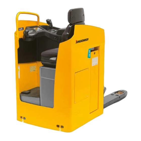
B Description of the truck Design and application The ESE 220 is an electric pallet truck with lateral seat in four-wheel design. It is pro- vided with a driver's seat with electric steering wheel control. The ESE 220 is designed for transport and order-picking operations on level ground. -
Page 11: Assemblies
Assemblies Item Designation Item Designation Information and service Battery door indicator Seat hood Travelling direction handle Drive wheel Master switch (emerg. stop) Supporting wheel 10 t Hood Dead man's switch 11 t Lifting device Parking brake t = Standard equipment o = Optional equipment... -
Page 12: Technical Data - Standard Version
Technical data - standard version Indication of technical data according to VDI 2398, subject to modification and supplementing. Performance data Designation Standard Rapid drive Q Rated capacity 2000 2000 Load centre distance Travelling speed 8,4 / 10,7 9,5 / 12,5 km/h with / without rated load Lifting speed... -
Page 13: Dimensions
Dimensions (all dimensions in mm) Designation Design length of front Height of fork when lowered Lift Seat height Truck width Distance between forks, outside 510 / 540 / 670 Track 340 / 370 / 500 Distance between forks, inside 170 / 200 / 330 Fork width Safety distance Dead weight... -
Page 15: En Standards
EN standards Continuous sound level: 68 dB(A) according to EN 12053 as stipulated in ISO 4871 The continuous sound level is a value averaged according to standard regulations, taking the sound pressure level into account when driving, lifting and idling. The sound pressure level is measured at the ear. -
Page 16: Labels
Labels 2000 1,5 V Kundendienst Regelmäßige Prüfung nach UVV VBG 12 a/ 12 b §20 durch Sachkundigen Nächste Prüfung Ihr Kundendienst-Partner Item Designation Capacity Qmax Travelling direction handle Label “CAUTION: Low-voltage electronics” Battery identification plate Attachment point of hooks for transportation by crane Test sticker (o) Truck identification plate The capacity label (12) indicates the maximum capacity of the truck as Qmax. - Page 17 Truck identification plate Item Designation Item Designation Type Manufacturer Serial No. Min./max. battery weight in kg Rated capacity in kg Drive power in kW Battery: Voltage V Load centre distance in mm Empty weight without battery in Year of manufacture Manufacturer logo Option In the event of queries relating to the truck or spare part orders, please state the serial...
-
Page 18: C Transportation And Commissioning
C Transportation and commissioning Transportation by crane Only lifting gear of adequate capacity must be used (for the transport weight, refer to the truck identification label). Bore holes for lifting screws (1) and hoi- sting points at the chassis (2) can be used if hoisting gear is to be used for transporting the truck. -
Page 19: Moving The Truck With The Drive Unit Inoperative
Moving the truck with the drive unit inoperative This operating mode is not permitted when negotiating inclines and gradients. If the truck has to be moved after a failure has rendered it immobile, proceed as follows: - Set the master switch to position “OFF”. - Set the key switch to position “OFF”... -
Page 20: D Battery
D Battery - servicing, recharging and replacement Safety regulations governing the handling of lead-acid batteries Before undertaking any operations on the batteries, park the truck and render it safe (refer to chapter E, section 4.4). Servicing staff: Recharging, servicing and replacing of batteries must only be per- formed by qualified personnel. -
Page 21: Battery Types
Battery types Depending on the truck version, the truck will be supplied with different battery types. 24V - PzS - Battery 3 PzS 330L (with weights) 24V - PzS - Battery 3 PzS 420L 24V - PzS - Battery performance-enhanced 3 PzS 450HX The battery weights can be seen on the battery identification plate. -
Page 22: Charging The Battery
Charging the battery To charge the battery, the truck must be parked in a closed and properly ventilated room. - Expose the battery (refer to chapter D, section 3). The battery connector (2) and the charging cable (4) must only be connected or dis- connected with the truck and the battery charger switched off. -
Page 23: Removing And Installing The Battery
Removing and installing the battery The truck must be parked on level ground. To prevent short-circuits, batteries with exposed poles or cell connectors must be covered using a rubber mat. Place the bat- tery connector or the battery cable, respectively, in such a way that they will not catch behind any truck protrusions when the battery is withdrawn. -
Page 24: Battery Discharge Indicator, Battery Discharge Monitor, Operating Hour Meter
Battery discharge indicator, battery discharge monitor, operating hour meter Battery discharge indicator: The loading status of the battery (9) is indicated in steps of 10% on the information and service indicator. The manufacturer setting of the battery discharge indicator / discharge monitor is standard batteries. -
Page 26: Safety Regulations Governing The Operation Of The Fork-Lift Truck
E Operation Safety regulations governing the operation of the fork-lift truck Driving permission: The fork-lift truck must only be operated by persons who have been trained in the operation of trucks, who have demonstrated to the user or his representative their capability of moving and handling loads, and who have expressly been charged by the user or his representative with the operation of the truck. -
Page 27: Description Of The Operating Controls And Indicators
Description of the operating controls and indicators Item Operating control or display Function t Switches the control current on and off. 1 Key switch When the key is removed from the key switch, the truck cannot be operated by unauthorised persons. o Shows, when alight, that the driver seat 2 Control lamp - driver seat heating... - Page 28 1 2 3 4...
-
Page 29: Starting Up The Truck
Starting up the truck Before starting or operating the truck, or before lifting any loads, the driver has to make sure that nobody is within the danger area. The electronic driving and steering systems automatically control their functions. If an error or fault occurs, the driving and steering functions are stopped. - Page 30 Adjusting the height of the foot space - Sit down on the seat. - Operate the foot space height adjust- ment key (15) to raise the floor. - Operate the foot space height adjust- ment key (15) and step on the floor. This will lower the floor plate.
- Page 31 (16) and travelling direction lever (7) are properly functioning (refer to chapter E, section 4.2). The truck is now ready for operation. JUNGHEINRICH The information and service indicator (5) briefly displays the vehicle code, followed by the current steering position of the drive wheel, the available battery capacity and the hours of operation.
-
Page 32: Operation Of The Fork-Lift Truck
Operation of the fork-lift truck Safety regulations applicable when operating the truck Driving lanes and work areas: Only such lanes and routes that are specially alloca- ted for truck traffic must be used. Unauthorised persons must stay away from work areas. -
Page 33: Driving, Steering, Braking
Driving, steering, braking Increased attention has to be paid during driving and steering the truck. Control the steering position of the drive wheel on the information and service indica- tor (18). The electric steering system is self-monitoring. The steering control systems monitors the fault frequency over a certain period. If the same fault is detected several times during this period, the steering control reduces the driving speed of the truck to low speed. - Page 34 Driving up an incline The load must be transported facing the incline! Safety measures against "rolling down" of the truck: With the travelling direction handle (7) set to neutral, the service brake is automati- cally applied after a brief jolt (the controller detects the truck’s rolling down on an incline).
- Page 35 Braking The braking behaviour of the truck strongly depends on the state of the floor. This must be taken into account by the driver for his driving behaviour. The truck may be braked in three ways: - using the service brake (break pedal (11)) - using the generator brake (coasting) - by counter-current braking (travelling direction handle (7)) In case of emergencies, the truck must only be braked using the service brake (break...
-
Page 36: Picking Up And Setting Down Loads
Braking by means of the generator brake (coasting) - Release the travelling direction lever (7) - travelling direction lever in home position ("0"). Depending on the setting, the truck is braked by the generator braked, coasting to a stop. The degree of speed reduction can be set by the manufacturer service. When the service personnel has switched off the coast-down brake, only the service and/or the counter-current brake can be used. -
Page 37: Safe Parking Of The Truck
Safe parking of the truck If the truck is left unattended, even for only short periods of time, it must be rendered safe. Never park the truck on a slope or incline. The lifting device must always be comple- tely lowered. - Operate the parking brake switch (16). -
Page 38: Information And Service Indicator (Lisa)
Information and service indicator (LISA) The LCD display (25) of the LISA information and service indicator indi- cates the battery charge status (24), the operating hours (27) and the posi- tion of the steered wheel (26). The BA T T : 1 0 % 2 0 h operating data is shown in the service and diagnosis mode... -
Page 39: Indicators
Indicators Operating data and error messages are displayed on the indicator. The operator menu can be used to set the following truck parameters: Here, the interval between maximum controller actuation SPEED DRIVE and 100% adjustment of the electronics is set. This driving parameter may only be adjusted by the DYNAMIC BRAKE (ROLL- custom service. -
Page 40: Changing Driving Parameters
Changing driving parameters The driving behaviour of the truck is changed if the truck parameters are modified. This is to be taken into consideration during start-up! Parameters may only be modified with the truck parked and while it is not performing any lifting movements. -
Page 41: Fault Location
Fault location This chapter enables the operator to locate and rectify minor faults and malfunctions, or the effects of operating errors. When trying to locate a fault, proceed in the order shown in the table. Fault Possible cause Remedial action Truck does - Battery connector not - Check the battery connector and... -
Page 42: F Maintenance Of The Fork-Lift Truck
F Maintenance of the fork-lift truck Operational safety and environmental protection The checks and servicing operations contained in this chapter must be performed in accordance with the intervals as indicated in the servicing checklists. Modifications of fork-lift truck assemblies, especially of the safety installations, are not permitted. - Page 43 Work on the electric system: Work on the electric system of the truck must only be performed by personnel specially trained for such operations. Before commencing any work on the electric system, all measures required to prevent electric shocks have to be taken. For battery-operated fork-lift trucks, the truck must also be depowe- red by removing the battery plug.
-
Page 44: Servicing And Inspection
Servicing and inspection Thorough and expert servicing is one of the most important preconditions for safe operation of the fork-lift truck. The neglect of regular servicing intervals can lead to fork-lift truck failure and constitutes a potential hazard to personnel and equipment. The indicated servicing intervals are based on single-shift operation under normal operating conditions. -
Page 45: Maintenance Checklist
Maintenance checklist Maintenance intervals standard cold store Chassis and Check all load bearing elements for damage superstruct. Check all bolted connections Check platform for correct functioning and damage Drive unit Check the transmission for noises and leakage Check the transmission oil level Change the transmission oil Wheels Check for wear and damage... - Page 46 Maintenance intervals standard cold store Battery Check acid density, acid level and cell voltage Check the terminals for secure attachment and apply grease Clean battery connections, check for tight seat Check the battery cables for damage, renew, if necessary Check whether the battery lock is fully functioning Lifting device 10.1 Performance and adjustment check 10.2 Perform sight check of rollers, sliding elements, and stops...
-
Page 47: Lubrication Schedule
Lubrication schedule 0,7 l A + C 1,25 - 1,3 l B + C Gliding surfaces Grease nipples Filler plug for hydraulic oil Filler plug for gear oil Drain plug for gear oil Cold store usage Compound for cold store usage 1:1 1.25l - 1.3l;... -
Page 48: Fuels, Coolants And Lubricants
Fuels, coolants and lubricants Handling consumption type material: Consumption type material must always be handled properly. Manufacturer's instructions are to be observed. Improper handling is injurious to health, life, and environment. Consumption type materials must be stored in adequate containers. They might be inflammable and, therefore, must not come into contact with hot components or open fire. -
Page 49: Instructions For The Servicing Operations
Instructions for the servicing operations Preparing the truck for servicing and maintenance operations All required safety measures must be taken to prevent any accidents in the course of the servicing and maintenance operations. The following preparatory operations must be performed: - Park the truck and render it safe (refer to chapter E, section 4.4). -
Page 50: Opening The Hood
Opening the hood - Using the service key (7), unlock the hood (8). - Swivel the hood (8) upwards. The drive current control system and the truck fuses are readily accessible for ser- vicing purposes. - Closing the battery door (3) , seat hood (6) and hood (8) is performed in reverse order. -
Page 51: Tightening The Wheel Screws
Tightening the wheel screws The wheel screws of the drive wheel must be retightened in accordance with the ser- vicing intervals indicated in the servicing checklist. - Position the drive wheel (10) at right angles to the longitudinal axis of the truck. - Tighten all wheel-fixing bolts (9) using a wrench which is to be inserted through the opening (11) of the collision guard (tightening torque 105Nm). -
Page 52: Checking The Electric Fuses
Checking the electric fuses - Prepare the truck for the servicing and maintenance operations (refer to chapter F, section 6.1). - Open the hoods (refer to chapter F, section 6.3 and 6.4). - Referring to the table, check all fuses for correct rating and damage; replace fuses where required. -
Page 53: Recommissioning The Truck
Recommissioning the truck Recommissioning of the truck following the performance of cleaning or maintenance work is permitted only after the following operations have been performed: - Check the horn for proper functioning. - Check the master switch for correct functioning. - Check the brake for correct functioning. -
Page 54: Recommissioning The Truck
Recommissioning the truck - Thoroughly clean the fork lift truck. - Lubricate the fork lift truck according to the lubrication chart (refer to chapter F). - Clean the battery. Grease the pole screws using pole grease and reconnect the battery. - Recharge the battery (refer to chapter D). -
Page 55: Safety Checks To Be Performed At Regular Intervals And Following Any Unusual Incidents
Carry out a safety check in accordance with national regulations. Junheinrich recom- mends checks in accordance with FEM Guideline 4.004. Jungheinrich has a special safety department with trained personnel to carry out such checks. The truck must be inspected at least annually (refer to national regulations) or after any unusual event by a qualified inspector. - Page 56 Jungheinrich traction battery Table of contents Jungheinrich traction battery ..........2-6 with positive tubular plates type EPzS and EPzB Type plate Jungheinrich traction battery..........7 Instruction for use ............8-12 Aquamatic/BFS III water refilling system Jungheinrich traction battery Maintenance free traction batteries with positive tubular plates type EPzV ....................13-17...
-
Page 57: Jungheinrich Traction Battery
Jungheinrich traction battery with positive tubular plates type EPzS and EPzB Rating Data 1. Nominal capacity C5: See type plate 2. Nominal voltage: 2,0 V x No of cells 3. Discharge current:: C5/5h 4. Nominal S.G. of electrolyte* Type EPzS:... - Page 58 Ignoring the operation instructions, repair with non-original parts or using additives for the electrolyte will render the warranty void. For batteries in classes I and II the instructions for maintaining the appropriate protection class during operation must be complied with (see relevant certificate). 1.
- Page 59 Battery container lids and the covers of battery compartments must be opened or re- moved. The vent plugs should stay on the cells and remain closed. With the charger switched off connect up the battery, ensuring that the polarity is cor- rect.
- Page 60 3. Maintenance 3.1 Daily Charge the battery after every discharge. Towards the end of charge the electrolyte level should be checked and if necessary topped up to the specified level with purified water. The electrolyte level must not fall below the anti-surge baffle or the top of the separator or the electrolyte „min“...
- Page 61 5. Storage If batteries are taken out of service for a lengthy period they should be stored in the fully charged condition in a dry, frost-free room. To ensure the battery is always ready for use a choice of charging methods can be made: 1.
-
Page 62: 7. Type Plate, Jungheinrich Traction Battery
7. Type plate, Jungheinrich traction battery Baujahr T ype Year of manufacture Serien-Nr. Lieferanten Nr. Serial-Nr. Supplier No. Nennspannung Kapazität Nominal V oltage Capacity Zellenzahl Batteriegewicht min/max Number of Cells Battery mass min/max Hersteller Jungheinrich AG, D-22047 Hamburg, Germany Manufacturer... -
Page 63: Aquamatic/Bfs Iii Water Refilling System
Aquamatic/BFS III water refilling system for Jungheinrich traction battery with EPzS and EPzB cells with tubular positive plates Aquamatic plug arrangement for the Operating Instructions Cell series* Aquamatic plug type (length) EPzS EPzB Frötek (yellow) (black) 2/120 – 10/ 600 2/ 42 –... - Page 64 Diagrammatic view Equipment for the water refilling system 1. Water tank 2. Level switch 3. Discharge point with ball valve 4. Discharge point with sole- noid valve 5. Charger 6. Sealing coupler 7. Closing nipple 8. Ion exchange cartridge with conductance meter and solenoid valve 9.
- Page 65 4. Filling (manual/automatic) The batteries should be filled with battery water as soon as possible before the battery charging comes to an end; this ensures that the refilled water quantity is mixed with the electrolyte. In normal operation it is usually sufficient to fill once a week. 5.
- Page 66 8. Battery hose connections Hose connections for the individual plugs are laid along the existing electric circuit. No changes may be made. 9. Operating temperature The temperature limit for battery operation is set at 55° C. Exceeding this temperature damages the batteries. The battery filling systems may be operated within a tempe- rature range of >...
- Page 67 10.2.1 Clamping ring tool The clamping ring tool is used to push on a clamping ring to increase the contact pres- sure of the hose connection on the plugs' hose couplings and to loosen it again. 10.3 Filter element For safety reasons a filter element (ident no.: 50307282) can be fitted into the batte- ry's main supply pipe for supplying battery water.
-
Page 68: Jungheinrich Traction Battery
Jungheinrich traction batterie Maintenance free Jungheinrich traction batterie with positive tubular plates type EPzV and EPzV-BS Rating Data 1. Nominal capacity C5: See type plate 2. Nominal voltage: 2,0 Volt x No of cells 3. Discharge current: C5/5h 4. Rated temperature: 30°... - Page 69 Ignoring the operation instructions, repair with non-original parts and non authorised interventions will render the warranty void. For batteries in classes I and II the instructions for maintaining the appropriate protection class during operation must be complied with (see relevant certificate). 1.
- Page 70 With the charger switched off connect up the battery, ensuring that the polarity is cor- rect (positive to positive, negative to negative). Now switch on the charger. When charging the temperature of the battery rises by about 15° C, so charging should only begin if the battery temperature is below 35°...
- Page 71 3.2 Weekly Visual inspection after recharging for signs of dirt and mechanical damage. 3.3 Quarterly After the end of the charge and a rest time of 5 h following should be measured and recorded: • the voltages of the battery •...
-
Page 72: 7. Type Plate, Jungheinrich Traction Battery
Batteries with this sign must be recycled. Batteries which are not returned for the recycling process must be disposed of as hazardous waste! We reserve the right make technical modification. 7. Type plate, Jungheinrich traction battery Baujahr T ype Year of manufacture Serien-Nr.
Need help?
Do you have a question about the ESE 220 and is the answer not in the manual?
Questions and answers