
Related Manuals for Magnetek IMPULSE G+


Summary of Contents for Magnetek IMPULSE G+
- Page 1 Digital Input Installation Manual August 2011 Part Number: 144-23918 © Copyright 2011 Magnetek...
-
Page 2: Preface And Safety
Any warnings provided by Magnetek must be promptly provided to the end user. Magnetek offers an express warranty only as to the quality of its products in conforming to standards and specifications published in the Magnetek manual. NO OTHER WARRANTY, EXPRESS OR IMPLIED, IS OFFERED. -
Page 3: Registered Trademarks
Terms ® Drive: IMPULSE •G+/VG+ Series 4 ® Option: IMPULSE •G+/VG+ Series 4 Option Digital Input DI-A3 DIO: Digital Input Option MFDI: Multi-Function Digital Input Registered Trademarks Trademarks are the property of their respective owners. Supplemental Safety Instructions Read and understand this manual before installing, operating, or servicing this option. Install the option according to this manual and local codes. -
Page 4: General Safety
Do not modify the drive or option circuitry. Failure to comply could result in damage to the drive or option and will void warranty. Magnetek is not responsible for any modification of the product made by the user. This product must not be modified. -
Page 5: Product Overview
2. Product Overview About This Product The Digital Input Option DI-A3 allows the user to expand the number of drive multi-function digital inputs. The input signal is +24 Vdc 8mA isolated input. IMPULSE®•G+/VG+ Series 4 Digital Input Installation Manual - August 2011... -
Page 6: Option Package Contents
3. Receiving Please perform the following tasks upon receiving the option: • Inspect the option for damage. Contact the shipper immediately if the option appears damaged upon receipt. • Verify receipt of the correct model by checking the model number printed on the option nameplate (refer to Figure 1 on page 7 for more information). -
Page 7: Option Components
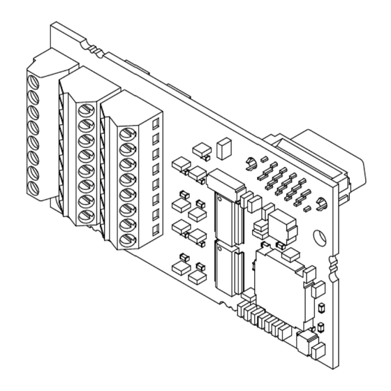
4. Option Components Digital Input DI-A3 Option <1> The ground wires provided in the option shipping package must be connected during installation. Figure 1: Digital Input DI-A3 Option Terminal Blocks TB1, TB2, and TB3 Figure 2: Terminal Blocks TB1, TB2, and TB3 Refer to Table 3 on page 20 for details on TB1, TB2, and TB3 terminal functions and signal levels. -
Page 8: Installation Procedure
5. Installation Procedure Section Safety D A N G E R Electric Shock Hazard Do not connect or disconnect wiring while the power is on. Failure to comply will result in death or serious injury. Disconnect all power to the drive and wait at least the amount of time specified on the drive front cover safety label. - Page 9 N O T I C E Damage to Equipment Observe proper electrostatic discharge (ESD) procedures when handling the option, drive, and circuit boards. Failure to comply may result in ESD damage to circuitry. Never shut the power off while the drive is running or outputting voltage. Failure to comply may cause the application to operate incorrectly or damage the drive.
-
Page 10: Prior To Installing The Option
Prior to Installing the Option Prior to installing the option, wire the drive, make the necessary connections to the drive terminals, and verify that the drive functions normally. Refer to the Quick Start Guide packaged with the drive for information on wiring and connecting the drive. Figure 3 shows an exploded view of the drive with the option and related components for reference. -
Page 11: Installing The Option
Installing the Option Refer to the instructions below to install the option. 1. Shut off power to the drive, wait the appropriate amount of time for voltage to dissipate, then remove the digital operator (D) and front covers (C, E). Refer to the Quick Start Guide packaged with the drive for directions on removing the covers. - Page 12 2. Insert the option card (B) into the CN5-A (J), CN5-B (K), or CN5-C (L) connector located on the drive and fasten it into place using one of the included screws (F). NOTE: Install the option to ports CN5-B and CN5-C on the drive for monitoring purposes only and input levels will be displayed in monitor U1-17.
- Page 13 3. Connect one end of the ground wire (H) to the ground terminal (I) using one of the remaining screws (G). Connect the other end of the ground wire (H) to the remaining ground terminal and installation hole on the option (B) using the last remaining provided screw (G). Figure 6: Connect the Ground Wire NOTE: 1.
- Page 14 4. Prepare and connect the wire ends as shown in Figure 7 and Figure 8. Refer to Wire Gauges, Tightening Torques, and Crimp Terminals on page 19 to confirm that the proper tightening torque is applied to each terminal. Take particular precaution to ensure that each wire is properly connected and wire insulation is not accidentally pinched into electrical terminals.
- Page 15 5. Wire the customer-supplied digital input signal to the terminal blocks on the option. Refer to Figure 9 for wiring instructions. Connection Diagram Refer to Table 3 on page 20 for a detailed description of the option board terminal functions. To ensure accurate control, use a stable power supply for the voltage reference source.
- Page 16 6. Set the option for SINK mode or SOURCE mode depending on the application. SINK Mode • To use the internal power supply of the drive, connect a wire jumper between terminals SP and • To use an external power supply, connect the positive lead from the power supply to terminal SC on the option.
- Page 17 7. Route the option wiring. Depending on the drive model, some drives may require routing the wiring through the side of the front cover to the outside. In these cases, cut out the perforated openings on the left side of the drive front cover as shown in Figure 12-A and leave no sharp edges to damage wiring.
- Page 18 8. Replace and secure the front covers of the drive (C, E) and replace the digital operator (D). Figure 13: Replace the Front Covers and Digital Operator NOTE: Take proper precautions when wiring the option so that the front covers will easily fit back onto the drive.
-
Page 19: Wire Gauges, Tightening Torques, And Crimp Terminals
0.25 to 1.5 (24 to 16 AWG) Crimp Terminals Magnetek recommends using CRIMPFOX 6 by Phoenix Contact or equivalent crimp terminals with the specifications listed in Table 2 for wiring to ensure proper connections. Table 2: Crimp Terminal Sizes Phoenix... -
Page 20: Terminal Functions
Terminal Functions Table 3: Option Terminal Functions Terminal Terminal Description Block DIO MDFI Terminal 1 DIO MDFI Terminal 2 DIO MDFI Terminal 3 DIO MDFI Terminal 4 DIO MDFI Terminal 5 DIO MDFI Terminal 6 DIO MDFI Terminal 7 DIO MDFI Terminal 8 DIO MDFI Terminal 9 DIO MDFI Terminal 10 DIO MDFI Terminal 11... -
Page 21: Related Parameters
6. Related Parameters The parameters outlined in the following sections are used to set up the drive for operation with the option. Set parameters as needed. Parameter setting methods can be found in the drive Quick Start Guide or Instruction Manual. Table 4: Related Parameters Parameter Initial... -
Page 22: Troubleshooting
7. Troubleshooting Drive-Side Error Codes Table 5 lists the various fault codes related to the option. Refer to the drive’s Instruction Manual for further details on fault codes. Check the following items first when an error code occurs on the drive: •... -
Page 23: Preventing Noise Interference
Digital Operator Display Fault Name Option Fault (CN5-C) oFC02 Two of the same options are connected simultaneously Cause Possible Solution DI-A3 option connected to CN5-C port Only one of these options, DI-A3, AI-A3, or SI-XX can be while another option was connected to connected to the drive at the same time. -
Page 24: Specifications
8. Specifications Table 6: Option Specifications Items Specifications Model DI-A3 Input Terminals 18 terminals (including SET and SIGN signals) Binary 16-bit,4-digit BCD Input Signal Type Binary 12-bit, 3-digit BCD (Parameter Settings) Binary 8-bit, 2-digit BCD SINK, SOURCE, external power supply Input Signal Photocoupler input: 24 VDC, 8 mA Ambient...
Need help?
Do you have a question about the IMPULSE G+ and is the answer not in the manual?
Questions and answers