ACV HeatMaster 201 Installation, Operation And Maintenance Instructions
Hide thumbs
Also See for HeatMaster 201:
- Installation, operating and servicing instructions (28 pages) ,
- Manual (2 pages) ,
- Product manual (49 pages)

Subscribe to Our Youtube Channel
Related Manuals for ACV HeatMaster 201


Summary of Contents for ACV HeatMaster 201
- Page 1 INSTALLATION, OPERATION AND MAINTENANCE INSTRUCTIONS for the Installer and the User HeatMaster A1004320 - 664Y7500 • A...
-
Page 2: Table Of Contents
TABLE OF CONTENTS GENERAL RECOMMENDATIONS ..................3 CONFIGURATION AND SYSTEM SET-UP ..............30 Safety Instructions..................................3 Basic Configuration - HeatMaster 201 : High Temperature Heating Circuit with Control by Room Ther- mostat and Optional Outdoor Sensor..........................30 USER’S GUIDE ........................4 STARTING UP ......................... 31 Meaning of Symbols ..................................4... -
Page 3: General Recommendations
• In spite of the strict quality standards that ACV applies to its appliances during production, inspection and transport, faults may occur. Please immediately notify your approved installer of any faults. -
Page 4: User's Guide
Domestic Hot Water circuit number (N°) of the appliance are indicated on its rating plate and must Primary circuit be provided to ACV in case of warranty claim. Failure to do so will make the claim void. Connection to the sewage system... -
Page 5: Nl Control Panel And Display
System temperatures. must be released and the procedure performed again to switch between increasing and decreasing Status line: displays the current oper- contrast. ating state of the appliance. See “Status Messages” on page 7. HeatMaster 201: A1004320 - 664Y7500 • A... -
Page 6: Stand-By Screen
USER’S GUIDE STAND-BY SCREEN STATUS MESSAGES This screen is displayed at start-up. It indicates that the appliance is ready to respond when a demand is Stand-by Indicates that the appliance is ready to respond when a demand is received. received. CH Demand A central heating call has been received. -
Page 7: What To Check On A Regular Basis
ACVMax controller. The EZ setup function allows the user/installer to quickly set up the appliance for immediate operation according to the system configuration*. ACV recommends to check the system at least every 6 months as follows: • Check that the system water pressure is at least 1 bar when cold. If the pressure drops below General remarks 0.7 bar, the built-in pressure sensor blocks the appliance until the pressure exceeds 1.2 bar. - Page 8 USER’S GUIDE Heating Easy setup (no outdoor sensor connected) To navigate on the screen, use the UP, DOWN, LEFT and RIGHT keys, • Use the OK key to validate a selection. • To increase/decrease values, use the UP and DOWN keys, or LEFT and RIGHT, according to the situation. •...
- Page 9 Press OK to return to EZ Setup Menu The Warm Weather Shutdown icon ( ) is displayed on the home screen when the outdoor temperature reaches the Warm Weather Shutdown preset temperature. Default: OFF. HeatMaster 201: A1004320 - 664Y7500 • A...
- Page 10 USER’S GUIDE EZ Setup Heating EZ Setup Warm Weather Shutdown Select CH Demand CH1 Setpoint CH2 Setpoint EZ Setup Complete 82°C 60°C Thermostat & Outd. Curve Heating EZ setup is complete. Constant & Outdoor Curve Additional changes can be made in Refer to page 9 for screen descriptions Constant &...
- Page 11 Press on LEFT or RIGHT button to adjust the required timeout value, if required, then press OK to store the the Installer Menu if required. 120 min. setting and complete the DHW setting. Press OK to return to EZ Setup Menu Defau lt: Off HeatMaster 201: A1004320 - 664Y7500 • A...
- Page 12 USER’S GUIDE Starting from the Home screen : Easy Setup Reset HeatMaster 84°C EZ Setup 61°C Target = 85°C EZ Setup Reset allows to reset all EZ EZ Setup Reset EZ Setup Reset Boiler Protection setup settings back to the original factory defaults.
- Page 13 Boiler Firing Rate 6. No error 27 h ago them and get more details through the Lockout Details screen. For more informa- Ionization current 44μA tion, refer to the Installer’s Handbook of the appliance. HeatMaster 201: A1004320 - 664Y7500 • A...
-
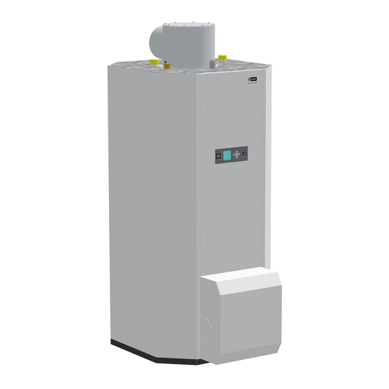
Page 14: Appliance Description
The HeatMaster® 201 boiler is equipped with ACV's "Tank-in-Tank" concept, as well as high efficiency charging pumps and with an ACV air/gas premix burner BG-2000 M with low NOx emissions. During op- eration, the burner starts automatically as soon as the appliance temperature gets lower than the preset temperature and stops as soon as the preset temperature is reached. -
Page 15: Connections - At The Back And On The Top
10. Pre-cut panel for gas connection (left and right sides) Heating supply connection [F] Auto air vent Heating return connection [F] 12. Filling loop connection Drain valve Grommets for electrical connection (to be installed) HeatMaster 201: A1004320 - 664Y7500 • A... -
Page 16: Air/Gas Pre-Mix Burners Acv Bg 2000-M/201
APPLIANCE DESCRIPTION AIR/GAS PRE-MIX BURNERS ACV BG 2000-M/201 Operation The power continually adjusts itself according to demand; this greatly improves the operating efficiency for heating and hot water. The burner tube is covered with a metal fibre (NIT), which, besides its remarkable heat exchange capacity, guarantees longer burner life. -
Page 17: Technical Characteristics
HM 201 Recommended 1000 A (mm) Minimum Recommended B (mm) Minimum Recommended 1000 C (mm) Minimum Recommended D (mm) Minimum Recommended 1300 E (mm) Minimum 1100 1018 mm 1395 mm 510 mm 210 mm HeatMaster 201: A1004320 - 664Y7500 • A... -
Page 18: Combustion Characteristics
91.0 Efficiency at 100% (50/30°C) — It is mandatory to use ACV flue systems to connect the appliance. Efficiency at 30% load (EN677) 94.0 : Connection to an exhaust duct that discharges the combustion products outside the room Combustion efficiency at 100% 91.5... -
Page 19: Gas Categories
I 2H I 3P I 3P I 3B/P I 2H I 3B/P I 3P I 2H I 2H I 3P I 3P I 3B/P I 3B/P I 2H I 2HS I 3B/P I 3B/P HeatMaster 201: A1004320 - 664Y7500 • A... -
Page 20: Pl Electrical Characteristics Heatmaster ® 201
TECHNICAL CHARACTERISTICS ELECTRICAL CHARACTERISTICS HEATMASTER ® HM 201 ON/OFF master switch Gas valve Main Characteristics Burner power supply Rated voltage Ground Rated frequency Burner PWM plug Max. Electrical consumption NTC2 return sensor Min. NTC1 supply sensor Electrical consumption at NTC - Low temperature circuit 30% load Electrical consumption in For low temp circuit operation, black wires from X3, terminals 1 &... - Page 21 NTC 3 NTC 4 0-10 Volt - Input 0-10 Volt - Ground ON / OFF Y/Gr Line Y/Gr 230 V Y/Gr Y/Gr Pump Y/Gr Y/Gr Alarm Y/Gr Y/Gr Flame Y/Gr Y/Gr Pump X100 HeatMaster 201: A1004320 - 664Y7500 • A...
-
Page 22: Hydraulic Characteristics
See "Recommendations for the Prevention of Corrosion and Scaling in Heating Systems" on the following page. Water flow rate (l/h) The hydraulics of the HeatMaster 201 boiler have been tested according to EN-15502, and the boiler is classified as a pressure class 3 appliance. HeatMaster201: A1004320 - 664Y7500 • A... -
Page 23: Ru Recommendations For The Prevention Of Corrosion And Scaling In Heating Systems
A deaerator (on the appliance flow line) combined with a dirt separator (upstream of the appliance) must be installed according to the manufacturer's instructions. - ACV recommends using additives that keep the oxygen in solution in the water, such as Fernox (www.fernox.com) and Sentinel (www.sentinel-solutions.net) products. -
Page 24: G3 Requirements And Guidance - Uk Only
TECHNICAL CHARACTERISTICS G3 REQUIREMENTS AND GUIDANCE - UK ONLY 3.55 Any discharge should be visible at the tundish. In addition, where discharges from safety devices may not be apparent, e.g. in dwellings occupied by people with im- paired vision or mobility, consideration should be given to the installation of a suitable safety Discharge pipe from safety valves device to warn when discharge takes place, e.g. - Page 25 28mm Up to 9m 1.0m G¾ 22mm 35mm Up to 8m 1.4m 42mm Up to 27m 1.7m 35mm Up to 9m 1.4m 28mm 42mm Up to 8m 1.7m 54mm Up to 27m 2.3m HeatMaster 201: A1004320 - 664Y7500 • A...
-
Page 26: Installation
• Only use ACV flue systems to connect this appliance to ensure that the pipe and For UK specific requirements for the discharge from safety valves, refer to «G3 Require- connection diameters all match. -
Page 27: Package Contents
Installation of the Front Panel and the burner cover” on page 29 : TOOLS REQUIRED FOR THE INSTALLATION For gas connection, remove the pre-cut section from the burner cover, according to the side from which gas pipe arrives to the appliance pressure (mbar) HeatMaster 201: A1004320 - 664Y7500 • A... -
Page 28: Hydraulic Connections
INSTALLATION HYDRAULIC CONNECTIONS DHW CONNECTION General remark • The circuit illustrations are basic principle diagrams only. Description 1. Isolating valve Essential recommendations for safety 2. Pressure reducing valve 3. Check valve • The hot water output may reach temperatures in excess of 60°C, which can cause 4. -
Page 29: Removal And Installation Of The Front Panel And The Burner Cover
• Control the gas pressure and consumption at appliance start up. • Check the appliance CO adjustment (refer to the adjustment procedure and the technical data). HeatMaster 201: A1004320 - 664Y7500 • A... -
Page 30: Configuration And System Set-Up
Thermostat & Outd. Curve Constant & Outdoor Curve Constant & Setpoint 0 - 10 V Modulation Signal The illustrations are for information only. For more details on the required accessories, refer to the latest ACV price list. HeatMaster201: A1004320 - 664Y7500 • A... -
Page 31: Starting Up
Essential recommendation for the correct operation of the appliance Check there is no leak. • Control the tightness of the hydraulic circuit connections. * UK specifi c reference G24.1 & G24.2 of the Water Regulations Guide. HeatMaster 201: A1004320 - 664Y7500 • A... -
Page 32: Starting Up The Appliance
It must be equal to the value at full power, or lower than that value by 0.5% maximum. If there is a significant deviation, please contact ACV's support department. Bleed the central heating circuit once again and top it up with water to get the required pressure if necessary. -
Page 33: Maintenance
Burner Electrode”, page 35. (mbar) APPLIANCE SHUT DOWN FOR MAINTENANCE Switch the appliance off using the ON/OFF master switch and isolate the external power supply. Close the gas supply valve of the appliance. HeatMaster 201: A1004320 - 664Y7500 • A... -
Page 34: It Heatmaster® 201 Overview
MAINTENANCE DRAINING THE APPLIANCE REMOVAL AND INSTALLATION OF THE BURNER DRAINING THE BOILER Set-up conditions Essential recommendations for safety • Appliance shut down • Before draining the DHW tank, drain the heating (primary) circuit or bring its • External power supply isolated pressure to 0 bar. -
Page 35: Removal, Check And Installation Of The Burner Electrode
(3). Connect the hose (1) to the gas valve (2). Follow-on tasks • Reinstall the burner. Refer to “Removal and Installation of the Burner” on page 34. 10-15 mm 3 - 5 mm HeatMaster 201: A1004320 - 664Y7500 • A... -
Page 36: De Dimensions
LOCKING CODES Codes Description of the fault Solution for the fault 1. Check gas supply to appliance. 2. Check Ignition cable connection in control box. E 01 Failed ignition: The burner failed to light after 5 ignition attempts. 3. Check electrode for defects, and distance between the pins. 4. - Page 37 2. Wait a few minutes for the water to equalise the temperature, the appliance will automatically reset once tempera- E 81 Sensor Drift: Supply and return temperatures are not equal. tures become equal. 3. If appliance doesn't reset, check the NTC's and check the wire harness, replace if necessary. HeatMaster 201: A1004320 - 664Y7500 • A...
- Page 38 LOCKING CODES Codes Description of the fault Solution for the fault 1. Verify fl ow in the system. Delta T protection blocking - Delta T too high 2. Check pump for blockage and obstructions, unblock it as required. Replace if neccessary. 1.
- Page 39 SERVICE LOG Service date CO2 % Flue gas T° Efficiency Remarks Name Signature HeatMaster 201: A1004320 - 664Y7500 • A...
-
Page 40: Declaration Of Conformity
DECLARATION OF CONFORMITY HeatMaster201: A1004320 - 664Y7500 • A...
Need help?
Do you have a question about the HeatMaster 201 and is the answer not in the manual?
Questions and answers