
Related Manuals for ACV Compact Condens 170


Summary of Contents for ACV Compact Condens 170
- Page 1 INSTALLATION, OPERATION AND MAINTENANCE INSTRUCTIONS for the Installer and the User Compact Condens 170 - 210 - 250 - 300 A1003043 - 664Y7200 • A...
-
Page 2: Table Of Contents
Boiler Shut-down for Maintenance ............................. 30 Gas Categories .....................................17 Periodic Boiler Maintenance Tasks ............................30 Electrical Characteristics Compact Condens 170 - 210 - 250 - 300 ................18 Draining the Heating Circuit of the Boiler .........................31 NTC resistance ....................................18 Removal, Check and Installation of the Burner Electrodes ..................31 Wiring Diagram and Electrical Connections ........................18... -
Page 3: General Recommendations
The manufacturer reserves the right to change the technical characteristics and features of its products without prior notice. • In spite of the strict quality standards that ACV applies to its appliances during production, inspection and transport, faults may occur. Please immediately notify your approved installer of any faults. -
Page 4: User's Guide
USER’S GUIDE MEANING OF SYMBOLS Symbols on the Symbols in the packaging Meaning manual Meaning Essential recommendation for safety (safety of persons and equipment) Fragile Essential recommendation for electrical safety (electrical hazard) Keep dry Essential recommendation for the correct operation of the appliance or the system Keep standing, up General remark... - Page 5 At the back of the boiler The part number (Typ) and serial number of the appliance are indicated on its rating plate and must be provided to ACV in case of warranty claim. Failure to do so will make the claim void. Compact Condens 170...
-
Page 6: Control Panel And Display
USER’S GUIDE CONTROL PANEL AND DISPLAY Home screen : It shows the status of CH and DHW Red keys: Allow to select specific items on the display, circuits (ON or OFF, as defined by the user/installer in as well as increase/decrease the values shown on spe- the setup), the activation of the anti-freeze function, cific screens (when associated with “+”... -
Page 7: What To Check On A Regular Basis
Check the list of faults and corresponding codes below to get the solution(s). If no solution is provided here, Essential recommendations for the correct operation of the appliance please contact your installer who will determine the correct solution. ACV recommends to check the system at least every 6 months as follows: Fault •... -
Page 8: Boiler Setup Guide For The User
USER’S GUIDE BOILER SETUP GUIDE FOR THE USER Through the User menu, the following parameters can be set : The main parameters of the Compact Condens boilers can be set up by the user using the user setup func- tion of the controller. It allows the user/installer to quickly setup the appliance for immediate operation Heating The user can define the CH set point, the outside temperature at which the heat- according to the system configuration. -
Page 9: User's Menu And Parameter Descriptions
USER’S GUIDE USER’S MENU AND PARAMETER DESCRIPTIONS The Heating menu allows to: CH set point 1. CH temperature/OTC set HEATING Set the CH temperatures and OTC curve parameters : Outside temperature for CH off • CH set point : to adjust the set point of flow temperature 2. -
Page 10: Installer's Guide
Once it is connected to the terminal strip of the boiler, the outdoor sensor is automatically • Air pressure switch, connected to the venturi, checks the amount of air (by means of a Δp meas- detected by the controller. Please contact your ACV representative for more details and the correct urement) before start. accessories. -
Page 11: Boiler Setup Guide For The Installer
INSTALLER’S GUIDE BOILER SETUP GUIDE FOR THE INSTALLER Start up process During heat demand the pump is activated by the controller. After zero-check of the air pressure switch The parameters of the Compact Condens boilers can be set up by the installer using the Technician setup the fan speeds up to airflow-check fan speed. -
Page 12: Installer's Menu And Parameter Descriptions
INSTALLER’S GUIDE INSTALLER’S MENU AND PARAMETER DESCRIPTIONS The Advanced CH Settings menu allows to: Maximum power 1. CH power set Set % of boiler maximum / minimum power in CH mode Minimum power Show and set boiler CH temperatures: • Set absolute CH max temperature that CH circuit will never exceed Absolute max temperature 2. - Page 13 INSTALLER’S GUIDE The System Settings menu allows to: Ignition power Define several boiler parameters: 1. Boiler parameters Delay siphon check • Set power % used during ignition boiler • Delay time to validate a siphon error Number of boiler pump •...
- Page 14 The Restore factory settings menu allows restore all the advanced settings to the original default factory settings by pressing on OK. RESTORE FACTORY SETTINGS Please contact your ACV representative to get the default values for your appliance. Compact Condens : A1003043 - 664Y7200 • A...
-
Page 15: Appliance Description
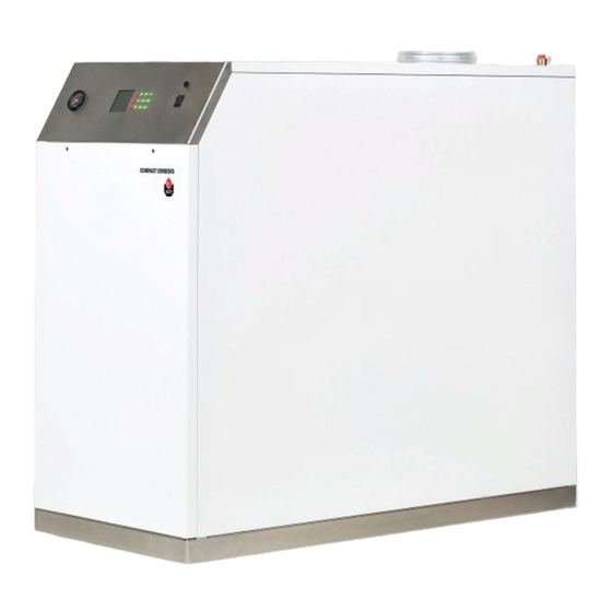
APPLIANCE DESCRIPTION MODELS - COMPACT CONDENS 170- 210 - 250 - 300 The Compact Condens is a floor-installed gas condensing boiler meeting the requirements of current “HR- Top” standards in Belgium. The boiler is certified compliant with “EC” standards as a connected appliance: C33(x) - C53(x) - C63(x) , but it can also be connected as an open appliance in category B23, which can operate with a positive pressure. -
Page 16: Technical Characteristics
TECHNICAL CHARACTERISTICS DIMENSIONS COMPACT CONDENS “ “ Min. of flue pipe Drained weight Clearance required (on access side(s)) 1000 1000 1000 1000 Compact Condens : A1003043 - 664Y7200 • A... -
Page 17: Combustion Characteristics
TECHNICAL CHARACTERISTICS COMBUSTION CHARACTERISTICS GAS CATEGORIES Gas type Pressure (mbar) COMPACT CONDENS Country code Category I 2H I 2E(R) Input (PCI) I 2H 33.6 50.4 58.8 I 2H Output at 100% (80/60°C) 163.6 204.5 245.4 282.5 I 2H (80/60°C) 97.4 97.4 97.4 97.4... -
Page 18: Electrical Characteristics Compact Condens 170 - 210 - 250 - 300
TECHNICAL CHARACTERISTICS ELECTRICAL CHARACTERISTICS COMPACT CONDENS 170 - 210 - 250 - 300 WIRING DIAGRAM AND ELECTRICAL CONNECTIONS Description To be connected to COMPACT CONDENS Burner Control Main Characteristics Display Rated voltage Connector 230V Rated frequency Connector low voltage Electrical consumption... - Page 19 TECHNICAL CHARACTERISTICS green-yellow green-yellow green-yellow green-yellow green-yellow green-yellow Fr-MP green-yellow black brown Ignition green-yellow Fr-CP D-X05 Trafo green-yellow Fr-FP black brown brown black blue white blue 230V white white yellow CH-P black 5 10 blue DHW-P 5 10 white blue CH-P 10 N black...
-
Page 20: Pneumatic Connections
Type NominalF low 7,2[ m 120,0 Compact Condens 170 (5 sections) and 300 (8 sections) 9[ m 110,0 A pneumatic diagram for the Floorflex 210 (6 sections) and the Floorflex 252 kW (7 A pneumatic diagram for the Floorflex 210 (6 sections) and the Floorflex 252 kW (7... -
Page 21: Recommendations For The Prevention Of Corrosion And Scaling In Heating Systems
SCALING IN HEATING SYSTEMS boiler) must be installed according to the manufacturer’s instructions. - ACV recommends using additives that keep the oxygen in solution in the water, such as How oxygen and carbonates can affect the heating system Fernox (www.fernox.com) and Sentinel (www.sentinel-solutions.net) products. -
Page 22: Tools Required For The Installation
Fill the condensate trap with water by pouring some water into the cast aluminium exhaust con- • Only use ACV flue systems to connect this appliance to ensure that the pipe and nection at the back. connection diameters all match. -
Page 23: Heating Connection
INSTALLATION REMOVAL AND INSTALLATION OF THE FRONT AND SIDE PANELS HEATING CONNECTION Typical connection - high temperature Set-up conditions Description • External power supply isolated Isolating valve Heating pump Removal Procedure Filling valve Front panel Check valve Using a cross-head screwdriver, release two screws (1) located at the top of the front panel. Retain Safety valve for re-installation. -
Page 24: Boiler Marking
It is mandatory to ventilate the boiler room. The high or low air vent opening dimensions It is mandatory to use ACV flue systems to connect the appliance. depend on the boiler power and the boiler room size. Refer to the local regulations in force. -
Page 25: Calculation Of The Flue Pipe Length
Ø200 mm Elbow (90°) Ø150 mm 12.0 16.4 Ø200 mm Elbow (45°) Ø150 mm The following tables are based on ACV equipment and cannot be applied as a rule. Ø200 mm C33 Terminal 16.4 25.7 36.9 50.3 Ø150 mm B23 Terminal Ø200 mm... -
Page 26: Gas Connection
• The CO , gas flow rate, air flow rate and air/gas supply parameters are factory- tact your ACV representative. preset and may not be modified in Belgium, except for type I 2E(R)B boilers. • Do not change the OFFSET (A) setting of the gas valve: it is factory-preset and sealed. -
Page 27: Basic Configuration - Compact Condens: High Temperature Heating Circuit Controlled By Room Ther- Mostat And Optional Outdoor Sensor
The heating pump is triggered as soon as the room thermostat generates a heat demand. The illustrations are for information only. For more details on the required accessories, refer to your ACV representative. For electrical detail, refer to wiring diagram in “Wiring Diagram and Electrical Connections” on page 18. -
Page 28: Starting Up
STARTING UP SAFETY INSTRUCTIONS FOR STARTING UP FILLING THE HEATING CIRCUIT General remark If the system is fitted with an external hot water tank, first put the DHW circuit under pressure before pressurizing the heating (primary) circuit. Refer to the hot water preparation tank •... -
Page 29: Starting Up The Boiler
0.5%. In case of significant devia- prevent certain circuits or radiators from getting a flow rate that is far above or below the set rate. tion, please contact ACV's Maintenance department. Follow-on tasks Follow-on tasks Check that there are no leaks. -
Page 30: Maintenance
MAINTENANCE PERIODIC BOILER MAINTENANCE TASKS SAFETY INSTRUCTIONS FOR THE BOILER MAINTENANCE Essential recommendations for the electrical safety • Turn off the boiler by pushing on the ON/OFF master switch. Frequency • Isolate the external power supply of the appliance before performing any Periodic 1 year 2 years... -
Page 31: Draining The Heating Circuit Of The Boiler
MAINTENANCE REMOVAL, CHECK AND INSTALLATION OF THE BURNER ELECTRODES DRAINING THE HEATING CIRCUIT OF THE BOILER Essential recommendations for the correct operation of the appliance Essential recommendations for safety Remove the electrodes to control them in case of ignition problems. •... -
Page 32: Removal, Check And Installation Of The Burner
MAINTENANCE REMOVAL, CHECK AND INSTALLATION OF THE BURNER Set-up conditions • Boiler shut down • External power supply isolated • Gas supply closed • Front and side panel(s) removed (refer to “Removal and Installation of the Front and Side Panels” on page 23). -
Page 33: Cleaning The Exchanger
Procedure Make sure there is no gas leak at the gas connections. Open the inspection sump cover, refer to “Models - Compact Condens 170- 210 - 250 - 300” on page Switch the appliance on using the ON/OFF master switch. - Page 34 TROUBLESHOOTING GENERAL Problem Probable cause(s) Solution(s) On/Off Master switch on “O” position Place On/Off Master switch on “ I “ position Fuse (5,0 AT) in the control panel blown THIS FUSE IS PART OF THE 230 V CIRCUIT. SO FIRST SWITCH OFF FROM THE MAIN ! Check fuse - Replace as required Connect the boiler to the power supply 1.
-
Page 35: Troubleshooting
TROUBLESHOOTING DHW CIRCUIT Problem Probable cause(s) Solution(s) Boiler does not respond to DHW operation OFF Activate DHW operation through control panel. Refer to “Installer’s menu and parameter descriptions” on page 12. DHW heat request Faulty storage tank-NTC or thermostat Check the storage tank-NTC or thermostat and its wiring, refer to “Wiring Diagram and Electrical Connections” on page 18. Insufficient DHW flow Insufficient water pressure Check water pressure from the mains... -
Page 36: Locking Codes
2. Check Pump and pump electrical connections. E 04 Air flow/damper Please contact your ACV representative. 1. Check blower and wiring harness. 2. Under normal condition if actual fan speed is 1000 rpm different from set fan speed an error is displayed (after 60sec in E 05 Blower speed: Blower speed not correct or speed signal is not received by MAXSYS. - Page 37 1. Correct condition which caused limit to open. E 76 External Limit Open: An external automatic reset boiler limit has opened. 2. Boiler will automatically reset once external limit closes Please contact your ACV representative.. E 77 Siphon error Compact Condens : A1003043 - 664Y7200 • A...
- Page 38 LOCKING CODES Codes Description of the fault Solution for the fault E 80 Return > Supply: Return temperature is higher than supply temperature. Confirm water flows in boiler return and out boiler supply. 1. Check water is flowing through boiler. 2.
-
Page 39: Service Log
SERVICE LOG SERVICE LOG ΔP P siphon Gas flow Flow Return Flue gas pressure /h] or temp temp pressure T° Service date CO2 [%] Efficiency Remarks Name & Signature switch load [ppm] switch [°C] [°C] [°C] [kW] [mbar] [mbar] Compact Condens : A1003043 - 664Y7200 • A... -
Page 40: Declaration Of Conformity
DECLARATION OF CONFORMITY Compact Condens : A1003043 - 664Y7200 • A...
Need help?
Do you have a question about the Compact Condens 170 and is the answer not in the manual?
Questions and answers