Table of Contents
Advertisement
Quick Links
Download this manual
See also:
Instruction Manual
Advertisement
Table of Contents

Related Manuals for Videotec MAXIMUS MPX


Summary of Contents for Videotec MAXIMUS MPX
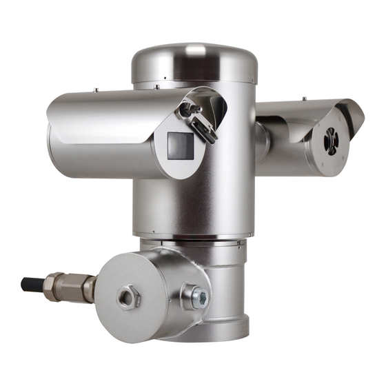
- Page 1 MAXIMUS MPX - MAXIMUS MPXT Explosion proof stainless steel PTZ positioning system English - Instructions manual...
-
Page 3: Table Of Contents
Contents ENGLISH 1 About this manual ......................7 1.1 Typographical conventions ..........................7 2 Notes on copyright and information on trademarks ..........7 3 Safety rules........................7 4 Identification ........................9 4.1 Product description and type designation..................... 9 4.1.1 Version with thermal imaging camera ...........................10 4.2 Product markings ..............................10 5 Preparing the product for use .................. - Page 4 6.1.16 Serial line terminations and connections ........................28 6.1.17 Setting the protocol ................................28 6.1.18 Setting the address................................28 6.1.19 Earth wiring connection ..............................29 6.1.20 Junction box closing ................................29 7 Instructions for safe operation ................... 30 7.1 Safe operation .................................30 7.1.1 Commissioning ..................................30 7.1.2 Safety rules ....................................31 7.1.3 Explosion prevention rules ..............................31 8 Switching on ........................
- Page 5 9.6.8 Default Menu ..................................50 9.6.9 Info Menu ....................................50 9.6.10 Thermal Camera Menu ..............................51 9.6.10.1 Flat Field Correction Menu ..................................52 9.6.10.2 Flat Field Correction Menu (Gain Switch Values) ..........................53 9.6.10.3 Video Setup Menu ....................................53 9.6.10.4 Gain Control Menu....................................54 9.6.10.5 ROI Setup Menu ......................................55 9.6.10.6 Thermal Analysis Menu ..................................55 9.6.10.7 Thermal Analysis Menu (Spot Meter) ..............................55 9.6.10.8 Thermal Analysis Menu (Isotherm) ..............................56...
- Page 6 14.1.3 Electrical/Video ..................................73 14.2 Communications ..............................74 14.2.4 Protocols ....................................74 14.2.5 Environment ..................................74 14.2.6 Certifications ..................................74 14.2.7 Brackets and adapters ...............................74 14.2.8 Accessories ....................................74 14.2.9 Package ....................................74 14.3 MPXT ..................................75 14.3.1 General ....................................75 14.3.2 Mechanical ....................................75 14.3.3 Electrical/Video ..................................75 14.4 Communications ..............................76 14.4.4 Protocols ....................................76 14.4.5 Environment ..................................76 14.4.6 Certifications ..................................76...
-
Page 7: About This Manual
1 About this manual 3 Safety rules Before installing and using this unit, please read this The manufacturer declines all responsibility manual carefully. Be sure to keep it handy for later for any damage caused by an improper use reference. of the appliances mentioned in this manual. - Page 8 • Read these instructions. • This device is remotely controlled and may change position at any time. It should be installed so that • Keep these instructions. no one can be hit by moving parts. It should be • Heed all warnings. installed so that moving parts cannot hit other •...
-
Page 9: Identification
4 Identification MAXIMUS PTZ offers continuous, high speed rotation, positioning precision and superior image quality, utmost sturdiness and simplified system 4.1 Product description and type configuration. designation Speed and precision are the predominant pan-and- tilt characteristics, reaching 100°/s in continuous The MAXIMUS series explosion-proof pan-tilt- horizontal rotation, with vertical range between -90°... -
Page 10: Version With Thermal Imaging Camera
4.1.1 Version with thermal imaging The high sensitivity NEdT 50mK at f/1.0 ensures an optimal thermal imaging. It supports 2x or 4x digital camera zoom. The device can be provided with a thermal imaging A choice of lens sizes is offered between 35mm, camera, which is installed inside a second housing, 25mm and 9mm, depending on the detection whose window is made mainly of germanium which... -
Page 11: Preparing The Product For Use
5 Preparing the product for The device can only be considered to be switched off when the power supply has been disconnected and the connection cables to other devices have been removed. Any change that is not expressly approved by the manufacturer will invalidate both A power disconnect device must be the guarantee and certification. -
Page 12: Unpacking And Contents
5.2 Unpacking and contents Single Mode/Multi Mode optical fiber version: • 1 explosion-proof 5.2.1 Unpacking • 1 sunshield (2 if version with thermal camera) When the product is delivered, make sure that the • 1 document Important safety instructions package is intact and that there are no signs that it •... -
Page 13: Preparatory Work Before Installation
5.4 Preparatory work before 5.4.1 Fixing to parapet or ceiling mount installation Attach the adapter (01) to the bottom of the unit using 4 stainless steel (A4 class 80) socket flat head cap screw M10 x 20mm (02). Use appropriate tools for the installation. The particular nature of the site where the Make sure the thread are free of dirt and debris. -
Page 14: Fixing With Bracket
5.4.2 Fixing with bracket 5.4.3 Fixing the unit to the pole mount adapter or corner mount adapter The bracket can be fixed to the vertical wall. Use screws and wall fixing devices that can bear at least To install the component on a pole or at a wall corner, four times the weight of the unit. -
Page 15: Fixing With Corner Adapter
5.4.3.2 Fixing with corner adapter 5.4.4 Fixing the sunshield Fix the wall bracket to the corner mount adapter Before running the wiring, fix the sunshield to the using 4 washers, 4 stainless steel grower washers camera housing using the screws and washers. 4 hexagon stainless steel bolts (A4 class 80) Apply a generous amount of thread locking M10x30mm. -
Page 16: Assembling And Installing
Videotec strongly recommend to test the device operation through the system’s software. configuration and performance in a office\laboratory Hardware adjustment is not required for inverted before putting it in the final installation site. -
Page 17: Connecting The Cables To The Base
6.1.3 Connecting the cables to the base It is only allowed to open the cover of the on-board junction box for cabling of the Before doing any technical work or device. The other lids must be open from maintenance on the device, make sure the manufacturer. -
Page 18: Cable Entry
Inside the junction box you'll find an address To make the wirings, unplug the removable and protocol board and a connectors board with connector from the connection board, cable all the removable connectors that make the cabling conductors on it and then plug the flying connector procedure easy. -
Page 19: Connection Of The Power Supply
6.1.5 Connection of the power supply Cable the wires on it. Always make the electrical connections with the power supply disconnected and the circuit-breaker open. ADDRESS & PROTOCOL When commencing installation make sure FUS2 VIDEO - 1 that the specifications for the power supply for the installation correspond with those VIDEO - 2 required by the device. - Page 20 Protective earth connections, use adequate cable The power supply cable should also be sections (up to 2.5mm² or AWG 14) covered by the silicone sheath (01) supplied for this purpose, and fastened with the corresponding tie (02). Furthermore, all signal cables must be grouped together by means of a strap (03).
-
Page 21: Connections Of One Or More Video Cables
6.1.6 Connections of one or more video 6.1.7 Connections of one or more cables optical fiber The installation is type CDS (Cable Use adequate optical fiber. Distribution System), do not connect it to SELV circuits. The transmission of video signal or data can be done by optical fiber. -
Page 22: Connection Of The Ethernet Cable
• Insert the silicone sheath supplied for this purpose. Crimping should be straight-through if passing via a hub or switch while it should be crossover if you • Combine the 2 optical fibers using ST-ST adapter are connecting directly to the PC for the necessary supplied. -
Page 23: Telemetry Line Connections
The example below shows a typical installation. • Pass the telemetry cables through the entry device. • Take the J9 removable female connector from the connectors board and connect the telemetry wires to it. UTP cat 5E Personal Hub / Switch Computer UTP cat 5E FUS2... -
Page 24: Alarm And Relay Connections
6.1.10 Alarm and relay connections 6.1.10.1 Connecting an alarm with clean contact (dry contact) The alarm contacts are present on J3 connector. For a clean contact alarm (alarms AL1, AL2, AL3, AL4 and AL5), carry out the following connection: Clean contact Fig. -
Page 25: Unit Address, Communication Protocol And Baud Rate Setting
6.1.11 Unit address, communication 6.1.12 Configuration of the dip-switches protocol and baud rate setting Operating mode valid only on version with Before powering the device it must be correctly IP board. configured by setting the dip switches on the circuit The unit can be configured in one way only. -
Page 26: Setting The Baud Rate
6.1.14 Setting the baud rate 6.1.15 Serial communication lines To set the baud rate operate on DIP 2. To set the serial communication lines operate on DIP 2. DIP 2 The product is designed with two RS485 serial communication lines which can have various settings according to the positions of dip-switches 5 and 6 on the DIP selector. -
Page 27: Two-Way Rs485 Tx/Rx Line
6.1.15.1 Two-way RS485 TX/RX line 6.1.15.3 Two-way RS422 line With this type of setting it is possible to obtain a This setting allows full duplex communication bi-directional, half/duplex, communication on the according to the RS422 standard. RS485-1 line. Line RS485-1 is always in receiving mode (RS422-RX). The RS485-2 serial line is not used. -
Page 28: Serial Line Terminations And Connections
Every peripheral that is situated at the end of a line SENSORMATIC must be terminated using the appropriate dip-switch PELCO D in order to prevent signal reflection and distortion. MACRO (VIDEOTEC) Dip-switches 7 and 8 terminate serial lines RS485-1 Tab. 8 and RS485-2 respectively. 6.1.18 Setting the address... -
Page 29: Earth Wiring Connection
Videotec technical support. Verify that in the cap there isn’t dirt or debris. Lubricate the threaded part of the lid, of the junction box and the seal with technical vaseline oil lubricant. -
Page 30: Instructions For Safe Operation
7 Instructions for safe Use a 30mm wrench for tightly closing the threaded cap of the junction box. Make sure that there’s no gap operation between the threaded cap and the junction box tube after tightening the cap. 7.1 Safe operation Before proceeding with the following operations, make sure that the mains voltage is correct. -
Page 31: Safety Rules
7.1.2 Safety rules 8 Switching on Given the considerable weight of the system, use an The automatic pre-heating (de-ice) process appropriate transport and handling system. could be started whenever the device is Before starting any operation, make sure the power switched on and the air temperature is supply is disconnected. -
Page 32: Configuration
9.2 How to move around the 9 Configuration menus 9.1 On Screen Menu (OSM) Each page of the OSM shows a list of parameters or During the normal operation of the unit it is possible sub-menus that can be selected by the operator. To to activate the On Screen Menu in order to set the scroll through the parameters move the cursor by advanced functions using the corresponding keys... -
Page 33: How To Change The Settings
9.3 How to change the settings 9.4 How to change the numeric fields Move the cursor to the parameter to be changed and confirm. The field will start flashing, indicating that Move the cursor to the parameter to be changed and it is in change mode. -
Page 34: How To Change Text
9.5 How to change text The Confirm command (Zoom Tele) inserts the desired character. Move the cursor to the parameter to be changed and confirm. EDIT TEXT: AREA ------------------------ Text: TEXT AREA1 EDIT ZONE ↑ ------------------------ A B C D E F G ERASE 1 NR H I J K L M N... -
Page 35: Configuring The System
9.6 Configuring the system 9.6.3 Camera menu Configuration: Sets one of the default 9.6.1 Main menu configurations for the SONY module: • Standard: Sets the standard operating mode MAIN MENU for the camera. ------------------------ • Low Light: Sets the operating mode for dimly 1>LANGUAGE >... -
Page 36: Zone Titling Menu
9.6.3.1 Zone Titling Menu 9.6.3.2 Zone Titling Menu (Edit Zone) This function allows setting up to eight (variable Once inside the Edit Zone menu it is possible to set dimension) areas with titling option. the following parameters. From the Zone Titling menu it is possible to set the Number: Selects the area to be edited. -
Page 37: Masking Menu
9.6.3.3 Masking Menu Setting the Start and Stop values of the Edit Dynamic masking allows the creation of up to a Zone menu to zero will disable text display. maximum of 24 masks so as to obtain the masking of If there are overlapping areas, the area with certain areas defined by the user. -
Page 38: Masking Menu (Edit Masks)
9.6.3.4 Masking Menu (Edit Masks) 9.6.3.5 How to create a new mask Once inside the Edit Masks menu it is possibile to set Choose a disabled mask by selecting Mask Number the following parameters: from the Edit Masks menu. Select Edit Mask to edit it. (Fig. -
Page 39: How To Modify A Mask
9.6.3.6 How to modify a mask • When the desired result is obtained press the Iris Open. Choose an enabled mask by selecting Mask Number from the Edit Masks menu (Fig. 71, page 38). Select Edit Mask to edit it. MASK 1 PTZ Motions Enabled •... -
Page 40: Advanced Setting Menu
9.6.3.7 Advanced Setting Menu 9.6.3.8 Advanced Setting Menu (Zoom) This menu is used to configure the SONY module. Zoom Speed: Sets the speed of the zoom. The speed ranges between 0 (minimum speed) and Zoom: Allows access to the Zoom submenu. 7 (maximum speed). -
Page 41: Advanced Setting Menu (Focus)
9.6.3.9 Advanced Setting Menu (Focus) 9.6.3.10 Advanced Setting Menu (Exposure) Once inside the Focus menu it is possible to set the Once inside the Exposure menu it is possible to set following parameters: the following parameters: Focus speed: Sets the speed of the Focus. The 1-5. -
Page 42: Advanced Setting Menu (Infrared)
9.6.3.11 Advanced Setting Menu (Infrared) The following table shows the inserted values with the corresponding effects on the SONY module lens. Once inside the Infrared menu it is possible to set the following parameters: CORRESPONDING VALUES/EFFECTS ON THE SONY MODULE LENS IR Mode: If set to OFF it forces the day mode in a continuous manner (the switching on of the illuminator (if present) is carried out by means... -
Page 43: Advanced Setting Menu (White Balance)
9.6.3.12 Advanced Setting Menu (White To avoid false switching, we recommend Balance) choosing the higher day switching Once inside the White Balance menu it is possible to threshold and delay values. set the following parameters: Mode: Sets the type of control on White INFRARED Balance. -
Page 44: Advanced Setting Menu (Other)
9.6.3.13 Advanced Setting Menu (Other) • Wind Mode: Sets the movements speed to adjust them to environments subject to Sharpness: Sets the sharpness value of the vibrations and/or windblasts. image. • High Perf: Establishes that all the movements High Resolution: Enables the High Resolution are carried out at the maximum possible function. -
Page 45: Manual Control Menu
9.6.4.1 Manual Control Menu 9.6.4.2 Manual Control Menu (Limits) Maximum Speed: Sets the maximum manual Once inside the Limits menu it is possible to set the speed. following parameters: Fast Mode: Enables the Fast mode. When Pan Limits: Enables the limits of Pan. enabled, this option is used to move fastly the Pan Start: Sets the start limit of Pan. -
Page 46: Preset Menu (Edit Preset)
9.6.4.4 Preset Menu (Edit Preset) 9.6.4.5 Preset Menu (Preset Utilities) Once inside the Edit Preset menu it is possible to set Once inside the Utilities Configuration menu it is the following parameters: possible to set the following parameters: Number: The Preset number to be edited. Daytime A.Focus: Enables the use of the autofocus when loading the preset in daytime Enabling: Enabling preset. -
Page 47: Patrol Menu
9.6.4.6 Patrol Menu 9.6.4.8 Motion Recall Menu First Preset: Sets the first preset of the Patrol It is possibile to set the unit so that, after a given sequence. inactivity interval, it automatically carries out the movement function set by the operator. Last Preset: Sets the last preset of the Patrol sequence. -
Page 48: Advanced Menu
9.6.4.9 Advanced Menu 9.6.5 Display Menu Static Control: Enables control of the position PTZ Positions: If not on OFF, it is used to select only when the pan & tilt is stopped how the Pan, Tilt and Zoom positions are displayed on the screen. -
Page 49: Options Menu
9.6.6 Options Menu From the Alarms menu it is possible to access one of the menus (Alarms 1-5) to edit the alarms parameters. Ceiling Mount: When this mode is enabled the From these menus it is possible to set the following image and the movements controls are turned values: upsidedown. -
Page 50: Washer Menu
9.6.7 Washer Menu 9.6.8 Default Menu The unit offers the possibility to use a wiper and to Delete Setup: Resets all the parameters except operate a pump to clean the glass. the Presets. To configure the Washer put the lens of the camera in Delete Preset: Deletes all previously stored front of the nozzle of the Washer. -
Page 51: Thermal Camera Menu
9.6.10 Thermal Camera Menu Gain control: Allows access to the gain control management submenu. Control: Sets the type of control on the thermal ROI Setup: Allows access to the ROI camera. management submenu. • Internal: The camera configuration is Thermal Analysis: Allows access to the thermal managed by the pan &... -
Page 52: Flat Field Correction Menu
9.6.10.1 Flat Field Correction Menu Gain mode: Allows the setting of dynamic gain range type: The thermal camera is fitted with an internal • High: This setting aims to maximize the mechanism which periodically improves the quality contrast and is especially suitable for of the images called Flat Field Correction (FFC). -
Page 53: Flat Field Correction Menu (Gain Switch Values)
9.6.10.2 Flat Field Correction Menu (Gain 9.6.10.3 Video Setup Menu Switch Values) Once inside the Video Configuration menu it is possible to set one of the following parameters: Once inside the Gain Switch Values menu it is possible to set one of the following parameters: Lut polarity: Sets the hue of the image shot by the thermal camera. -
Page 54: Gain Control Menu
9.6.10.4 Gain Control Menu Plateau value: Sets the maximum pixel value which can be found in a grey scale. Once inside the Gain Control Configuration menu it is ITT Mean: Sets the mean point on a grey scale. possible to set one of the following parameters: Max Gain: Sets the maximum gain of the AGC. -
Page 55: Roi Setup Menu
9.6.10.5 ROI Setup Menu 9.6.10.7 Thermal Analysis Menu (Spot Meter) Once inside the ROI Configuration Menu it is Once inside the Point Measurement menu it is possible to change the region of interest (ROI) used possible to set one of the following parameters: by the AGC algorithm to calculate the contrast and Mode: Enables the visualization of the taken brightness levels of the image. -
Page 56: Thermal Analysis Menu (Isotherm)
9.6.10.8 Thermal Analysis Menu (Isotherm) 9.6.10.9 Status Menu Once inside the Isotherm menu it is possible to Once inside the Status menu it is possible to learn the enable a special colouring for objects included within technical features of the thermal camera. the set temperature interval. -
Page 57: Ip Board Configuration
9.7 IP Board Configuration Enter address 192.168.0.100. you will have to log in with a password. 9.7.1 Minimum system requirements The default account name is: Admin (with a capital A). Choose one of the following configurations, The default password is: 123456 according to the number of channels to be When making the settings for the first time, insert the controlled. -
Page 58: Wan Setting
9.7.2.1 WAN setting Continue by pressing the Install button. You carry out this procedure once and only once for each PC that is Keep the account and the password in a to have access to the device in the network. secure place. - Page 59 Then edit the other parameters, for example: Before doing any technical work or • Date Setting: To set date and time. maintenance on the device, make sure • Video Setting: To change resolution (720x576, that potentially explosive atmosphere is 640x480, 352x288, 176x144) bit rate (setting not present.
-
Page 60: Installing The Nvr Software
Repeat the procedure with the cable of the thermal Fig. 121 camera(02), if present. Select Videotec NVR Professional and follow the When finished change the O-ring gasket (new O-ring instructions that appear on the screen. is in the package), lubricate it and the threads with technical vaseline oil. - Page 61 The first time you run the program, the following When setting up manually, it is essential (as in display will appear, with an empty camera list automatic setup, apart from the IP address) to set the (Camera Tree). items marked by an asterisk, i.e. Camera ID: Consecutively, 1, 2, 3 etc.
-
Page 62: Controlling Ptz Movements
Media Source list. Check the Enable PTZ box. Click on Apply. This will automatically set the VIDEOTEC Macro protocol at 38400 baud. Repeat the procedure for the other units to be controlled, directly from the PTZ setup menu ; just... -
Page 63: Preset And Load Positions
9.7.3.2 Preset and load positions To set the configuration parameters of the pan & tilt by means of OSM, enable the corresponding function Before making these settings, we using the control panel. recommend enabling Mouse PTZ control, so that it is easier to move around in the position to be saved. -
Page 64: Instructions For Safe Operation
10 Instructions for safe Set the preset positions for the other units in the same way. operation Close the NVR application and re-start it to save the settings. 10.1 Visualizing the state of the When the application is re-started, the preset pan &... -
Page 65: Saving The Current Position (Preset)
10.2 Saving the current position 10.5 Enabling Autopan Function (Preset) Using the control keyboard it is possible to enable the Autopan (for further information, refer to the manual 10.2.1 Quick save of the keyboard in use or to Tab. 11, page 68). Using the control keyboard it is possible to save the Disabling can be carried out by moving the joystick current position (for further information, refer to the... -
Page 66: Recalling The Home Position
10.7 Recalling the Home position 10.9 Enabling the Washer (Washer) Using the control keyboard it is possible to recall a previously saved Home position (Scan No. 1) Do not use the wiper when the outside (for further information, refer to the manual of the temperature is below 0°C or in case of ice. -
Page 67: Manual Correction Of A Preset Focusing
10.11 Manual correction of a preset focusing Load the preset whose focus needs to be changed using the Scan command; change the focus using the appropriate keys Focus Far/Focus Near without changing the Pan/Tilt/Zoom position; then save the preset using the appropriate Preset command. - Page 68 SPECIAL CONTROLS Control Protocol MACRO PELCO D SENSORMATIC ERNITEC PANASONIC Reboot the Save Preset 94 Save Preset 94 Save Preset 94 Save Preset 94 Save Preset 94 device Ini+ Faster+ Zoom out+ Save Preset 61 Focus far+ Iris open Enabling Save Preset 95 Save Preset 95 Save Preset 95...
-
Page 69: Maintaining And Cleaning
Using these products will irreparably damage the germanium surface. When contacting Videotec for assistance please go Once done cleaning, reassemble the spacer and the to the configuration and statistic page and send a grid. -
Page 70: Extraordinary (To Be Done Only Under Particular Circumstances)
Whenever replacing the parts as indicated, This symbol means that electrical and electronic always use VIDEOTEC original spare parts equipment, at their end-of-life, should be disposed of and meticulously follow the maintenance separately from your household waste. -
Page 71: Troubleshooting
13 Troubleshooting The monitor does not show PROBLEM the picture taken but shows Ask for assistance from skilled personnel if: an image of the type: • The unit is damaged after being dropped; Address : 1 • There is noticeable deterioration in performance Protocol : MACRO of the unit. - Page 72 Error E3-PATROL WITHOUT SOLUTION Wait until the end of the pre-heating PROBLEM procedure. If the air temperature is PRESET or error E4-PATROL, 1 too low the unit will remain disabled PRESET ONLY. and the following message will be The presets have not been CAUSE shown: programmed.
-
Page 73: Technical Data
1 video output 75 Ohm 1Vpp (PAL/NTSC) Functions: Autopan, Preset, Patrol, Tour (maximum 3), Autoflip Maximum number of presets: - VIDEOTEC MACRO Protocol: 250 - ERNITEC protocol: 250 - PANASONIC protocol: 250 - PELCO D Protocol: 99 - AMERICAN DYNAMICS protocol: 95... -
Page 74: Communications
The product may be interfaced with devices not manufactured by OCTEXBA3/4C Barrier cable gland 3/4" NPT, VIDEOTEC. It is possible that the interface protocols have changed or armoured cable IECEX-ATEX- are in a different configuration from earlier tested units by VIDEOTEC. -
Page 75: Mpxt
2 video outputs 75 Ohm 1Vpp (PAL/NTSC) Functions: Autopan, Preset, Patrol, Tour (maximum 3), Autoflip Maximum number of presets: - VIDEOTEC MACRO Protocol: 250 - ERNITEC protocol: 250 - PANASONIC protocol: 250 - PELCO D Protocol: 99 - AMERICAN DYNAMICS protocol: 95... -
Page 76: Communications
The product may be interfaced with devices not manufactured by OCTEXBA3/4C Barrier cable gland 3/4" NPT, VIDEOTEC. It is possible that the interface protocols have changed or armoured cable IECEX-ATEX- are in a different configuration from earlier tested units by VIDEOTEC. -
Page 77: Electrical Rating
14.5 Electrical rating ELECTRICAL RATING Power Supply Normal usage to be specified on product label Short term de-icing cicle. Peak maintaining a mini- mum internal temp at 5°C 230Vac 0.11A, 50/60Hz, 25.3W 0.52A, 50/60Hz, 120W 24Vac 1.08A, 50/60Hz, 25.9W 5A, 50/60Hz, 120W 120Vac 0.21A, 50/60Hz, 25.2W 1A, 50/60Hz, 120W... -
Page 78: Camera
14.7 Camera ANALOGUE CAMERAS AVAILABLE SONY Day/Night 36x SONY Day/Night 28x High sensitivity NTSC NTSC Optical zoom Wide Dynamic Range (Fix/Auto) • True progressive SCAN • Digital image stabilisation • • White balance Auto, ATW, Indoor, Outdoor (Fix/ Auto, ATW, Indoor, Outdoor (Fix/ Auto), Sodium Vapor Lamp (Fix/ Auto), Sodium Vapor Lamp (Fix/ Auto) - Page 79 THERMAL CAMERAS AVAILABLE (RESOLUTION 160X120) Lens 19mm Lens 13mm Lens 9mm NTSC NTSC NTSC Image sensor Uncooled VOx microbolometer Uncooled VOx microbolometer Uncooled VOx microbolometer Resolution 160x120 160x120 160x120 160x120 160x120 160x120 Pixel dimensions 25μm 25μm 25μm Spectral response - long wave infrared (LWIR) from 7.5μm to 13.5μm from 7.5μm to 13.5μm from 7.5μm to 13.5μm...
- Page 80 EN - English - Instructions manual THERMAL CAMERAS AVAILABLE (RESOLUTION 320X256) Lens 35mm Lens 25mm Lens 19mm Lens 13mm Lens 9mm NTSC NTSC NTSC NTSC NTSC Image sensor Uncooled VOx microbo- Uncooled VOx microbo- Uncooled VOx microbo- Uncooled VOx microbo- Uncooled VOx microbo- lometer lometer...
- Page 81 THERMAL CAMERAS AVAILABLE (RESOLUTION 336X256) Lens 35mm Lens 25mm Lens 19mm Lens 13mm Lens 9mm NTSC NTSC NTSC NTSC NTSC Image sensor Uncooled VOx microbo- Uncooled VOx microbo- Uncooled VOx microbo- Uncooled VOx microbo- Uncooled VOx microbo- lometer lometer lometer lometer lometer Resolution...
- Page 82 EN - English - Instructions manual THERMAL CAMERAS AVAILABLE (RESOLUTION 640X512) Lens 35mm Lens 25mm Lens 19mm Lens 13mm Lens 9mm NTSC NTSC NTSC NTSC NTSC Image sensor Uncooled VOx microbo- Uncooled VOx microbo- Uncooled VOx microbo- Uncooled VOx microbo- Uncooled VOx microbo- lometer lometer...
-
Page 83: Technical Drawings
15 Technical drawings The dimensions are in millimetres. Ø 138 Ø 138 N°4 M10 N°4 M10 Fig. 137 MAXIMUS MPX. - Page 84 Ø 138 Ø 138 N°4 M10 N°4 M10 Fig. 138 MAXIMUS MPXT.
-
Page 85: A Appendix - Marking Codes
A Appendix - Marking codes A.1 ATEX Marking Fig. 139 Ï ÐÐ Ex d ÐÐC Tfi -40°C to +60°C Group (surface Category (high Explosion-proof Gas group Gas temperature Installation temperature range Protection level device, no mining) protection degree, housing for po- classification of the equipment the device in this... -
Page 86: Iecex Mark
EN - English - Instructions manual A.2 IECEx Mark Fig. 140 Ex d ÐÐC Tfi -40°C to +60°C Explosion-proof housing for po- Gas group Gas temperature classification Installation temperature range Protection level of the equipment tentially explosive environments for gas Ex tb ÐÐÐC T85°C... -
Page 87: Gas Group Classification
A.3 Gas group classification The table below shows the classification of some gases and vapours, according to the explosion-proof protection group and the temperature class. For a complete list see IEC/EN 60079-12 and IEC/EN 60079-20. GAS GROUP CLASSIFICATION Temperature class (Maximum surface temperature of the housing) 1 Class 450°C (842°F) 300°C (572°F) -
Page 88: B Appendix - Flamepath
B Appendix - Flamepath The maximum constructional gap (ic) is less than that required by Table 2 of EN 60079-1:2007 as detailed below: MAXIMUM GAP MINIMUM WIDTH FLAMEPATH COMMENT (MM) (MM) Between component drawings 0.249 25.4 Cylindrical joint sup- BRT2MPXALBPAN and BRT2MPXTAPINF ported by bearings Between component drawings 0.245... - Page 90 Tel. +44 0113 815 0031 (Orders/Shipping dept.) Email: uksales@videotec.com France Videotec France S.à.r.l. Asia Pacific Videotec (HK) Ltd Voie du Futur, Zac des Portes - 27100 - Val-de-Reuil, France Unit C 24 Floor - Gold King Industrial Building Tel. +33 2 32094900 - Fax +33 2 32094901 35-41, Tai Lin Pai Road - Kwai Chung, NT, Hong Kong Email: info@videotec-france.com...
Need help?
Do you have a question about the MAXIMUS MPX and is the answer not in the manual?
Questions and answers