Table of Contents
Advertisement
Quick Links
Advertisement
Table of Contents

Related Manuals for Videotec DTRX3


Summary of Contents for Videotec DTRX3
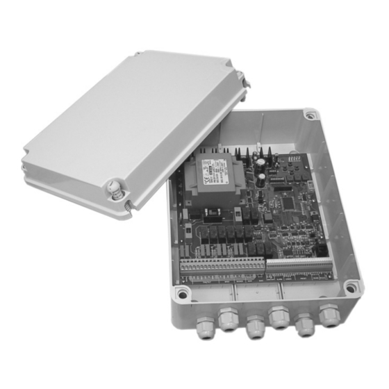
- Page 1 OPERATING INSTRUCTIONS...
-
Page 3: Table Of Contents
2 SAFETY RULES..............................3 3 OPERATING DATA ON THE RATING PLATE......................4 4 DESCRIPTION OF THE DTRX3 RECEIVER......................4 4.1 Features ................................4 4.2 Compatible devices for the use with the DTRX3 receiver ................5 4.3 Installation examples ............................5 4.4 Cables ................................6 5 INSTALLATION..............................7 5.1 Unpacking ...............................7 5.2 Control of the operating data on the rating plate....................7... - Page 4 15 DIP SWITCH SW4 AND SW6 CONFIGURATION TABLES ................21 16 TECHNICAL FEATURES ..........................21 17 DESCRIPTION OF THE DTRX324 RECEIVER....................22 17.1 Compatible devices for the use with the DTRX324 receiver ................22 18 TECHNICAL FEATURES ..........................23 The manufacturer assumes no responsibility for possible damages resulting from an improper use of the devices mentioned in this manual;...
-
Page 5: Introduction
2 Safety rules The DTRX3 receiver complies with the rules in force at the time of publication of the present manual as regards the electric safety, the electromagnetic compatibility and the other general requirements. -
Page 6: Operating Data On The Rating Plate
3 Operating data on the rating plate The DTRX3 receiver is supplied with two rating plates in conformity with the EC standards. The first plate contains: Model identification code (Extended 3/9 bar code) Power supply (Volt) Frequency (Hertz) Consumption (Watt) The second plate indicates the serial number of the model (Extended 3/9 bar code). -
Page 7: Compatible Devices For The Use With The Dtrx3 Receiver
4.2 Compatible devices for the use with the DTRX3 receiver WARNING! In case of using the DTRX324, refer to the paragraph 17. Compatible devices for the use with the DTRX324 receiver. Control keyboards: DCT, DCJ, DCTEL, DCIR, DCS3, DCS2, DCMT8 Pan &... -
Page 8: Cables
0,34 mm² (AWG 22) for low tension wires (lens, auxiliary devices, preset) 0,75 mm² (AWG18) for power supply cable of DTRX3 cable for the digital reception/transmission of commands: 2 wires for the reception from the control unit (twisted telephone pair, section 0.22 mm.² AWG 24) 2 wires for the possible transmission to the next cascade-connected receiver (twisted telephone pair, section 0.22 mm²... -
Page 9: Installation
5 Installation The unit must be installed exclusively by skilled technical personnel. Before carrying out the following operations, if not otherwise stated, always disconnect the unit. 5.1 Unpacking If the packaging does not present evident faults (due to falls or anomalous scratches), make sure that its contents correspond to the list of items contained in paragraph Contents of the packaging, in section Introduction. -
Page 10: Configuration Of The Receiver
Set SW1 to 0, SW2 to 2 and Sw3 to 7 Receiver address n.4 Set SW1 to 0, SW2 to 0 and SW3 to 4 6.2 DTRX3 receiving mode According to the communication type to set follow the following settings: Current Loop:... -
Page 11: Type Of Lenses Used
WARNING! An inaccurate protocol and/or communication speed selection can cause damages to the receiver. The DTRX3 receiver can be used in digital transmission systems and it can communicate with a speed from 300 to 38400 baud, depending on the used protocol. -
Page 12: Control Voltage Of The Positioning Device And The Wiper
6.6 Control voltage of the positioning device and the wiper WARNING!: An inaccurate setup of this parameter can cause damages to the positioning device and to wiper! This setting is not required for the DTRX324 receiver due to the fact that it supplies only a 24 V~ voltage. -
Page 13: Connection With The Rs485 Line
------- Black RX-485B Note: The receiver DTRX3 has the load inserted in reception and is connected to line A or B on the keyboard with the load inserted. On the receiver side it is also possible to make a simpler connection to terminals RX-485A and RX-485B as in the following scheme. -
Page 14: More Than One Receiver Per Line, Connection With Twisted Pair Cable (Multipoint Connection)
Keyboard phone cable RJ-Jack DTRX3 RS485A connectors white ------------------------ RX-485A RS485B yellow ------------------------ RJ11 ‘A’ or ‘B’ RX-485B Note: Terminals RX-485A and RX-485B which have the load inserted, should be connected to terminals TX- 485A and TX-485B respectively of the preceding unit, which also have the load inserted: NB: For the connection in question (point-to-point) faulty operation of one of the receivers will switch off all the devices in cascade. -
Page 15: Mixed Configurations (Point-To-Point / Multi-Point)
(R3 and R4) will not receive the commands. 6.10 Connection with the Current Loop line The various devices (keyboard DCS2, video matrix SM328B and receiver DTRX3) can be connected directly using the telephone cable supplied by the manufacturer: Connection DCS2 - receiver DTRX3... -
Page 16: Connection With The Rs232 Line
Note: from the Receiver side the connection should be made to terminals RXCL and AGND according to the following scheme: if the receiver is connected in cascade to another DTRX3 unit, the reception mode should be set in Current Loop with jumpers JP2 and JP3 in position CL. -
Page 17: Adjusting The Voltage Of The Optics Controls
7 Setting the receiver for PRESET functions The DTRX3 receiver has integrated preset functions (for pan&tilt and the optics). It is possible to store up to a maximum of 14 positions using the standard Videotec protocol or up to a maximum of 40 positions using the MACRO and Pelco D protocols. -
Page 18: Testing The Dtrx3 Receiver
8 Testing the DTRX3 receiver After having connected the positioning device and the lens cables, to check the correct working of the devices, it’s possible to perform an automatic test which will show the allowed functions:. WARNING! Since during this phase the positioning devices makes automatically some predetermined movements, do not lean on during the test and do not obstruct its trajectory. -
Page 19: Use Of The Alarm Contacts
(by keyboards). When the arrow- keys are released the receiver functions are fully restored. The combination of Up key and reset key is used to carry out the auto-test (see chap. relevant to Test of DTRX3 receiver). Page 17... -
Page 20: Pelco D Controls Recognised By The Dtrx3 Receiver
11 Pelco D controls recognised by the DTRX3 receiver As well as recognising standard Pelco D controls relating to joystick and lens movements, the DTRX3 receiver is able to recognise and execute the following extended Pelco D controls: Pelco D Control... -
Page 21: Switching On And Switching Off
Operating data on the rating plate. make sure that the fuses of the DTRX3 receiver are not damaged. make sure that the receiver and the other components of the plant are closed in order to avoid the direct contact with live elements. -
Page 22: Troubleshooting
14 Troubleshooting Although the DTRX3 receiver is characterized by a great ease of use, sometimes troubles may occur, especially during the installation and configuration phases or using the unit. PROBLEM PROBABLE CAUSE REMEDY Led LD1 is off No power supplied to the unit... -
Page 23: Dip Switch Sw4 And Sw6 Configuration Tables
15 Dip Switch SW4 and SW6 configuration tables Position Function Pelco D protocol Videotec or MACRO protocols (setting the dip 8 of SW4) 2 3 4 No action No one Position Function 9600 baud* (Videotec and MACRO), 2400 Pelco D... -
Page 24: Description Of The Dtrx324 Receiver
To supply the DTRX324 receiver in a correct way refer to the following scheme: Receiver power supply 24 V~ 50/60 Hz NB: For any other installation procedure, refer to the DTRX3 receiver description. (positioning device connection, lens, preset, protocol and baud rate settings, etc.). -
Page 25: Technical Features
18 Technical features Power supply: 24V~ 50/60 Hz Consumption 40 W Max switching power: 100 W Power supplied to the positioning device 24V~ 50/60 Hz Power supplied to the wiper 24V~ 50/60Hz Power supplied to the washer 24V~ 50/60 Hz Power supplied to the lens ÷... - Page 26 Page 24 MNVCDTRX301_0850...
Need help?
Do you have a question about the DTRX3 and is the answer not in the manual?
Questions and answers