Table of Contents
Advertisement
Available languages
Available languages
Quick Links
OPERATING INSTRUCTIONS
---------------------------------------------------------------------------------------------------------------------------------------------------------
MANUALE D'USO
---------------------------------------------------------------------------------------------------------------------------------------------------------
MANUEL D'INSTRUCTIONS
---------------------------------------------------------------------------------------------------------------------------------------------------------
BEDIENUNGSANWEISUNG
---------------------------------------------------------------------------------------------------------------------------------------------------------
РУКОВОДСТВО ПО ЭКСПЛУАТАЦИИ
Advertisement
Chapters
Table of Contents

Related Manuals for Videotec PTH310


Summary of Contents for Videotec PTH310
- Page 1 OPERATING INSTRUCTIONS --------------------------------------------------------------------------------------------------------------------------------------------------------- MANUALE D’USO --------------------------------------------------------------------------------------------------------------------------------------------------------- MANUEL D’INSTRUCTIONS --------------------------------------------------------------------------------------------------------------------------------------------------------- BEDIENUNGSANWEISUNG --------------------------------------------------------------------------------------------------------------------------------------------------------- РУКОВОДСТВО ПО ЭКСПЛУАТАЦИИ...
- Page 3 OPERATING INSTRUCTIONS...
-
Page 5: Table Of Contents
Typographic conventions .................................... 2 SAFETY RULES ..................................2 IDENTIFICATION DATA ................................ 3 DESCRIPTION OF PTH310 / PTH311 PAN & TILT MOTORS ..................... 3 Features ........................................3 Appliances compatible with PTH310 / PTH311 ............................3 ... -
Page 6: Pth310 - Pth311
Description of system features: read carefully to understand the following phases. Safety rules PTH310 / PTH311 pan & tilt motors comply with the normative laws in force at the time of editing of this manual, concerning electric safety, electromagnetic compatibility and general requirements. -
Page 7: Identification Data
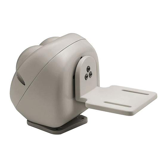
Description of PTH310 / PTH311 pan & tilt motors PTH310 / PTH311 unit is a vertical and horizontal pan & tilt motor, expressly projected for outdoor installations. PTH310P / PTH311P models have all the features of PTH310 / PTH311 models, in addition to the PRESET. -
Page 8: Installation
Adjustment of PTH310 / PTH311 pan & tilt motors CAUTION: Do not position the pan & tilt motor manually, since this operation may seriously damage the gears. -
Page 9: Adjustment Of The Potentiometer For Pth310P / Pth311P Preset Pan & Tilt Motor
Adjustment of the potentiometer for PTH310P / PTH311P preset pan & tilt motor This operation is very important for the correct working of the preset. PTH310 / PTH311 Pan & Tilt motors are still set in our works, therefore this procedure is to be made only in case of real necessity. -
Page 10: Connectors And Connections
1 monitor lense Telemetry handling: 1 PTH310 / PTH311 pan & tilt motor 1 motorized zoom lens Installation example One operator with more monitors, who controls a series of pan & tilt motors in mixed configuration (star and... -
Page 11: Cables
Cables Different types of stroke have been used in the previous examples, in order to indicate cables with different functions: video cable: RG 59 coaxial cable or equivalent cable multipolar cable: each control function of the positioning device is activated /deactivated by a relay positioned inside the receiver. Fix the final numbers of wires according to the following directions: 7 wires for the motion of the positioning device: right, left, up, down, autopan, common, ground 6 wires for the control of polarity reversal lenses (zoom, focus, iris) -
Page 12: Pan & Tilt Connection To Cbz Keyboard
Pan & tilt connection to CBZ keyboard WARNING: before the connection, make sure that the output voltage CBZ keyboard corresponds to pan & tilt voltage (Refer to the identification data of the keyboard and of the pan & tilt motor). Where to operate: J1 terminal block in the upper printed circuit of the pan &... -
Page 13: Switching On And Off
check that the material supplied corresponds to the specifications indicated on the data plate, following the chapter Identification data check that PTH310 / PTH311 pan & tilt motor and the other components of the installation are closed in order to avoid direct contact with energized parts. -
Page 14: Specifications
Cable diameter 10 mm EAC certification Electric features Power Supply PTH310 / PTH310P 230 V~ 50/60 Hz 7+7 W PTH311 / PTH311P 24 V~ 50/60 Hz 7+7 W Wiring 7 cables 0.56mm.² (AWG 20) (Functions: left, right, up, down, common, autopan and earth). - Page 15 MANUALE D’USO...
- Page 17 Apertura dell’imballaggio .................................... 4 Controllo della marcatura ................................... 4 REGOLAZIONE DEI BRANDEGGI PTH310 / PTH311 ......................4 Regolazione del potenziometro per il brandeggio con preset PTH310P / PTH311P .................. 5 CONNETTORI E COLLEGAMENTI ............................6 ...
-
Page 18: Introduzione
Controllare che il contenuto sia rispondente alla lista del materiale sopra indicata. Cosa contiene questo manuale In questo manuale sono descritti i brandeggi della serie PTH310 / PTH311, con le particolari procedure di installazione, configurazione e utilizzo. E’ necessario leggere attentamente questo manuale, in particolar modo il capitolo concernente le norme di sicurezza, prima di installare ed utilizzare il brandeggio. -
Page 19: Dati Di Marcatura
Descrizione dei brandeggi PTH310 / PTH311 L’unità PTH310 / PTH311 è un brandeggio verticale e orizzontale appositamente studiato per essere utilizzato in ambienti esterni. Le versioni PTH310P/ PTH311P hanno tutte le caratteristiche dei modelli PTH310 / PTH311 più il PRESET. -
Page 20: Installazione
Non effettuare per nessun motivo alterazioni o collegamenti non previsti in questo manuale: l’uso di apparecchi non idonei può portare a gravi pericoli per la sicurezza del personale e dell’impianto. Regolazione dei brandeggi PTH310 / PTH311 ATTENZIONE: Non posizionare il brandeggio manualmente poichè questa operazione può danneggiare seriamente gli ingranaggi. -
Page 21: Regolazione Del Potenziometro Per Il Brandeggio Con Preset Pth310P / Pth311P
Regolazione del potenziometro per il brandeggio con preset PTH310P / PTH311P Questa funzione e’ molto importante per il corretto funzionamento del preset. La seguente procedura deve essere eseguita sia per il potenziometro collegato al movimento orizzontale che per quello collegato al movimento verticale. Il brandeggio e’... -
Page 22: Connettori E Collegamenti
1 monitor dell’ottica Gestione della telemetria: 1 brandeggio PTH310 / PTH311 1 ottica motorizzata Esempio di installazione Un operatore con più monitor, con controllo di una serie di brandeggi in configurazione mista (a stella e in cascata) -
Page 23: Cavi
Cavi Negli schemi d’esempio sono stati utilizzati di versi tipi di tratto per indicare cavi di diversa funzione: cavo video: coassiale RG 59 o cavo equivalente. cavo multipolare: ogni funzione di controllo del brandeggio viene attivata / disattivata da un relè interno al ricevitore. Stabilire il numero finale di cavi, seguendo le indicazioni seguenti: 7 fili per la movimentazione del brandeggio: destra, sinistra, alto, basso, autopan, comune, terra 6 fili di controllo per ottiche ad inversione di polarità... -
Page 24: Collegamento Del Brandeggio Alla Tastiera Cbz
Collegamento del brandeggio alla tastiera CBZ ATTENZIONE: prima di eseguire i collegamenti assicurarsi che la tensione in uscita dalla tastiera CBZ corrisponda alla tensione del brandeggio (Fare riferimento ai dati di marcatura della tastiera e del brandeggio). Dove Agire: morsettiera J1 sulla scheda superiore del brandeggio (vedi figura) Impostazioni: collegare i fili provenienti dalla tastiera al brandeggio secondo la tabella seguente : Fili in uscita da CBZ Collegamento al... -
Page 25: Accensione E Spegnimento
controllare che il materiale fornito corrisponda alle specifiche richieste, esaminando le etichette di marcatura, secondo quanto descritto al capitolo Descrizione della marcatura. controllare che il brandeggio PTH310 / PTH311 e gli altri componenti dell’impianto siano chiusi e sia quindi impossi- bile il contatto diretto con parti in tensione. -
Page 26: Caratteristiche Tecniche
Peso 3.5 Kg (8 lb) Diametro cavo 10 mm Certificazione EAC Caratteristiche elettriche Alimentazione PTH310 / PTH310P 230 V~ 50/60 Hz 7+7 W PTH311 / PTH311P 24 V~ 50/60 Hz 7+7 W 0,56 mm.² (AWG 20) Cablaggio 7 fili (Funzioni: sinistra, destra, alto, basso, comune, autopan, Terra) 0,34 mm.²... - Page 27 MANUEL D’INSTRUCTIONS...
- Page 29 Contenu de ce manuel ....................................2 Conventions typographiques ..................................2 NORMES DE SECURITE ............................... 2 CARACTERISTIQUES TECHNIQUES ..........................3 DESCRIPTION DES TOURELLES PTH310 / PTH311 ......................3 Caractéristiques......................................3 Appareils compatibles ....................................3 INSTALLATION ..................................4 ...
- Page 30 Description des caractéristiques du système: lire attentivement pour comprendre les phases suivantes. Normes de sécurité La tourelle PTH310 / PTH311 est conforme aux normes en vigueur au moment de la publication de ce manuel pour ce qui concerne la sécurité électrique, la compatibilité électromagnétique et les conditions requises générales.
- Page 31 Caractéristiques techniques Sur les tourelles PTH310 / PTH311 il y a deux plaques conformes aux caractéristiques techniques CE. La première plaque contient: Code d’identification du modèle (Code à barre EXT3/9 ) Tension d’alimentation (Volt) Fréquence (Hertz) Max. consommation (Watt) La deuxième plaque indique le numéro de série du modèle (Code à...
- Page 32 Réglage des tourelles PTH310 / PTH311 ATTENTION: Ne pas forcer manellement l’orientation horizontale ou verticale sous peine de deteriorer le mecanisme de la tourelle et annuler la garantie.
- Page 33 Réglage du potentiomètre pour la tourelle avec préselection PTH310P / PTH311P Cette opération est très importante pour le correct fonctionnement de la préselection. Le réglage doit être systématiquement effectué pour le potentiométre horizontal et pour le potentiometre vertical. Le non respect de cette procedure entraine la destruction du potentiometre. La tourelle est déjà...
- Page 34 1 moniteur de l’objectif Gestion de la télémétrie: 1 tourelle PTH310 / PTH311 1 objectif motorisé Exemple d’installation Un opérateur avec plusieurs moniteurs, qui contrôle une série de tourelles en configuration mixte (à étoile et en ligne bus) MATERIEL EMPLOYÉ...
- Page 35 Câbles Dans les exemples, des traits différents ont été employés pour indiquer des câbles à fonctions diversifiées: câble vidéo: coaxial RG 59 ou câble équivalent câble multipolaire: chaque fonction de commande tourelle est activée / désactivée par un relais à l’intérieur du récepteur. Déterminer le nombre final de câbles, suivant les indications ci-dessous: 7 fils pour le mouvement de la tourelle: droite, gauche, haut, bas, autopan, commun, terre 6 fils de commande pour objectif fonctionnant par inversion de polarité...
- Page 36 Raccordement de la tourelle au pupitre CBZ ATTENTION: avant d’effectuer les raccordements, vérifier si la tension en sortie du pupitre CBZ correspond à la tension de la tourelle (Se rapporter aux caractéristiques techniques du pupitre et de la tourelle). Où l’on doit agir : plaque à bornes J1 sur la carte supérieure de la tourelle (voir figure). Réglages: raccorder les fils du pupitre à...
- Page 37 vérifier que le matériel fourni correspond aux spécifications requises, suivant les plaques des caractéristiques techniques, en se rapportant au chapitre Caractéristiques techniques. vérifier si la tourelle PTH310 / PTH311 et les autres composantes de l’installation sont fermées afin d’éviter le contact direct avec parties sous tension ...
- Page 38 3,5 Kg (8 lb) Diamètre câble 10 mm Certification EAC Données électriques Alimentation PTH310 / PTH310P 230 V~ 50/60 Hz 7+7 W PTH311 / PTH311P 24 V~ 50/60 Hz 7+7 W 7 câbles 0,56mm 2 (AWG 20) (Fonctions: gauche, droite, haut, bas, commun, autopan, Terre) Câblage...
- Page 39 BEDIENUNGSANWEISUNG...
- Page 41 Inhalt dieses Bedienungshandbuches ................................ 2 Typographische Symbole ................................... 2 SICHERHEITSBESTIMMUNGEN ............................2 BETRIEBSEIGENSCHAFTEN AUF DEN DATENSCHILDERN ................... 3 BESCHREIBUNG DER PTH310 / PTH311 -SCHWENKVORRICHTUNGEN ..............3 Eigenschaften ......................................3 Kompatibeln Apparate ....................................3 INSTALLATION ..................................4 ...
-
Page 42: Einleitung
Kontrollieren Sie, daß der Inhalt mit der oben angeführten Materialliste übereinstimmt. Inhalt dieses Bedienungshandbuches In diesem Handbuch sind die Schwenkvorrichtungen der Serie PTH310 / PTH311 beschrieben sowie die jeweiligen Vorgangsweisen zur Installation, Konfiguration und Verwendung. Es ist notwendig, das Handbuch und insbesondere das Kapitel in Bezug auf die Sicherheitsbestimmungen vor der Installation und Verwendung der Schwenkvorrichtung aufmerksam zu lesen. -
Page 43: Betriebseigenschaften Auf Den Datenschildern
Man kann die Auto-Pan-Funktion für einen begrenzten Zeitraum verwenden Kompatibeln Apparate Die Funktionierung den PTH310 / PTH311 -Schwenkvorrichtungen garantiert ist , nur wenn sie angeschlossen sind : CBZ-Tastatur : Bedienungstastatur für Schwenkvorrichtungen und Linsen Befehlsempfänger DTRX3: Digitalempfänger mit 17 Funktionen, ermöglicht die Fernbedienung einer motorisierten Schwenkvorrichtung, von Scheibenwaschern und Pumpen sowie von 4 Hilfskontakten. -
Page 44: Installation
Anschlüsse vorgenommen werden: die Verwendugn ungeeigneter Geräte kann zu großer Gefahr für die Sicherheit des Personals und der Anlage führen. Einstellung der PTH310 / PTH311 -Schwenkvorrichtungen VORSICHT: Positionieren Sie die Schwenkvorrichtung nicht manuell, denn dieses Verfahren kann die Getriebe schwer beschädigen. -
Page 45: Einstellung Des Potentiometers Für Die Schwenkvorrichtung Mit Preset Pth310P / Pth311P
Einstellung des Potentiometers für die Schwenkvorrichtung mit Preset PTH310P / PTH311P Folgende Prozedur gilt sowohl für den mit der horizontalen Bewegung verbundenen Potentiometer, als auch für den, der mit der vertikalen Bewegung verbunden ist. 1. Entfernen Sie die Versorgung von der Schwenkvorrichtung. -
Page 46: Verbinder Und Anschlüsse
1 DCS2-Bedienungstastatur Videoteil: 1 SW164OSM-Video-Umschalter 2 Monitoren DTRX3 DTRX3 DTRX3 4 Fernsehkameras DTRX3 Fernmessungsteil: 1 DCMX -Steuerung für serielle Ubertragungen 4 DTRX3-Empfänger 4 PTH310 / PTH311 - Schwenkvorrichtungen DCMX SW164OSM DCS2 Seite 6 MNVCPTH300_1541_DE... -
Page 47: Kabel
Kabel In den Exemplifizierungen wurden verschiedene Stricharten angewandt, um die mehreren Funktionen der Kabel zu bezeichnen. Video-Kabel: Koaxialkabel RG 59 oder gleichartiges Kabel Mehradriges Kable: Jede Steuerfunktion Schwenkvorrichtung wird einem Empfänger eingebauten Relais aktiviert/deaktiviert. Die endgültige Kabelnummer folgendermaßen festlegen: 7 Drähte für die Bewegung der Schwenkvorrichtung: rechts, links, oben, unten, autopan, gemeinsam, Erde 6 Drähte für die Steuerung der Umpolungslinsen (Zoom, Focus, Iris) 4 Drähte für die Linsen mit gemeinsamem Draht (Zoom, Focus, Iris) 2 Drähte für das Zusatzgerät. -
Page 48: Anschluß Der Schwenkvorrichtung An Der Cbz-Tastatur
Anschluß der Schwenkvorrichtung an der CBZ-Tastatur VORSICHT: bevor Sie die Anschlüße durchführen, vergewissern Sie sich, daß die Ausgangsspannung der CBZ-Tastatur der Schwenkvorrichtungsspannung entspricht (Beziehen Sie sich auf die Betriebseigenschaften auf den Datenschildern der Tastatur und der Schwenkvorrichtung). Eingriff: Klemmbrett J1 auf die obere Karte der Schwenkung (siehe Bild). Einstellungen: die von Tastatur herauskommenden Kabeln sind der Schwenkung, nach der folgendem Übersicht, zu verbinden. -
Page 49: Einschalten Und Ausschalten
Betriebsdaten laut der Beschreibung unter dem Kapitel Betriebseigenschaften auf den Datenschildern überprüft werden. überprüfen, ob die PTH310 / PTH311 -Schwenkvorrichtung und andere Komponenten der Anlage geschlossen sind und daher der direkte Kontakt mit unter Spannung stehenden Teilen unmöglich ist. -
Page 50: Technische Eigenschaften
Gewicht 3,5 Kg (8 lb) Kabeldurchmesser 10 mm EAC-Zertifizierung Elektrische Eigenschaften Erforderter Strom PTH310 / PTH310P 230 V~ 50/60 Hz 7+7 W PTH311 / PTH311P 24 V~ 50/60 Hz 7+7 W 7 Kabeln zu 0,56 mm 2 (AWG 20) (Funktionen: links, rechts, oben, unten, gemeinsam, autopan, Verdrahtung Erden). - Page 51 РУКОВОДСТВО ПО ЭКСПЛУАТАЦИИ...
- Page 53 Содержание данного руководства ................................2 Условные обозначения шрифтами................................2 ПРАВИЛА ТЕХНИКИ БЕЗОПАСНОСТИ ..........................2 ДАННЫЕ МАРКИРОВКИ ..............................3 ОПИСАНИЕ ПОВОРОТНЫХ УСТРОЙСТВ PTH310 / PTH311 ..................3 Характеристики ......................................3 Совместимые приборы .................................... 3 УСТАНОВКА ..................................4 ...
-
Page 54: Введение
При поставке изделия убедитесь в том, что упаковка не повреждена и не имеет явных признаков падений или царапин. В случае повреждения упаковки следует немедленно обратиться к поставщику. Убедиться, что содержимое соответствует указанному выше списку материалов. Содержание данного руководства В данном руководстве описываются поворотные устройства PTH310 / PTH311 и специальные процедуры для их установки, конфигурации... -
Page 55: Данные Маркировки
Данные маркировки На поворотных устройствах PTH310 / PTH311 имеются две этикетки, соответствующие маркировке СЕ. На первой этикетке приведена следующая информация: Идентификационный код модели (штрих-код Extended 3/9) Напряжение питания (Вольт) Частота (Гц) Потребление (Ватт) На второй этикетке указан серийный номер модели (штрих-код Extended 3/9) Во... -
Page 56: Установка
Ни в коем случае не выполнять непредусмотренные данным руководством соединения или изменения: использование несоответствующих приборов может стать причиной серьезных рисков для безопасности персонала и системы оборудования. Регулировка поворотных устройств PTH310 / PTH311 ВНИМАНИЕ: Не размещать поворотное устройство вручную, так как эта операция может серьёзно повредить шестерни. -
Page 57: Регулировка Потенциометра Для Поворотного Устройства С Предварительной Установкой Pth310P / Pth311P
Регулировка потенциометра для поворотного устройства с предварительной установкой PTH310P / PTH311P Данная функция очень важна для правильной работы программы предустановки. Следующая процедура должна выполняться для потенциометра, подсоединённого к механизму как горизонтального движения, так и вертикального. Поворотное устройство уже отрегулировано на заводе-изготовителе поэтому такая процедура должна быть... -
Page 58: Коннекторы И Соединения
Управление видео: 1 переключатель видео SW164OSM 2 монитора DTRX3 DTRX3 DTRX3 DTRX3 4 телекамеры Управение телекамерой: 1 контроллер связей DCMX 4 приёмника DTRX3 4 поворотных устройства PTH310 / PTH311 DCMX SW164OSM DCS2 Стр. 6 MNVCPTH300_1541_RU... -
Page 59: Кабели
Кабели В примере на схемах были использованы различные типы участка для обозначения кабелей различного назначения: видеокабель: коаксиальный кабель RG 59 или эквивалент. многожильный кабель: каждая функция контроля поворотного устройства активируется/отключается с помощью реле внутри приемника Установить итоговое количество кабелей, выполнив следующие указания: 7 проводов... -
Page 60: Соединение Поворотного Устройства С Кнопочной Панелью Cbz
Соединение поворотного устройства с кнопочной панелью CBZ ВНИМАНИЕ: перед тем как выполнить соединения убедиться, что напряжение на выходе кнопочной панели CBZ соответствует напряжению поворотного устройства (См. данные маркировки кнопочной панели и поворотного устройства). Где Выполнять Операцию: клеммная панель J1 на верхней плате поворотного устройства (см. рисунок) Настройки: подсоединить... -
Page 61: Включение И Выключение
проверяя маркировочные этикетки, как описано в главе Описание маркировки. проверить, что поворотное устройство PTH310 / PTH311 и другие компоненты в системе закрыты и, следовательно, прямой контакт с токоведущими частями невозможен. Проверить, чтобы все компоненты были закреплены хорошо и надежно. -
Page 62: Технические Характеристики
Вес 3.5 кг (8 lb) Диаметр кабеля 10 мм Сертификат EAC Электрические характеристики Питание PTH310 / PTH310P 230 В~ 50/60 Гц 7+7 Вт PTH311 / PTH311P 24 В~ 50/60 Гц 7+7 Вт 0,56 мм² (AWG 20) Кабельная проводка 7 проводов... - Page 63 OPERATING INSTRUCTIONS --------------------------------------------------------------------------------------------------------------------------------------------------------- MANUALE D’USO --------------------------------------------------------------------------------------------------------------------------------------------------------- MANUEL D’INSTRUCTIONS --------------------------------------------------------------------------------------------------------------------------------------------------------- BEDIENUNGSANWEISUNG --------------------------------------------------------------------------------------------------------------------------------------------------------- РУКОВОДСТВО ПО ЭКСПЛУАТАЦИИ...
- Page 65 OPERATING INSTRUCTIONS...
- Page 67 Typographic conventions .................................... 2 SAFETY RULES ..................................2 IDENTIFICATION DATA ................................ 3 DESCRIPTION OF PTH310 / PTH311 PAN & TILT MOTORS ..................... 3 Features ........................................3 Appliances compatible with PTH310 / PTH311 ............................3 ...
- Page 68 Description of system features: read carefully to understand the following phases. Safety rules PTH310 / PTH311 pan & tilt motors comply with the normative laws in force at the time of editing of this manual, concerning electric safety, electromagnetic compatibility and general requirements.
- Page 69 Description of PTH310 / PTH311 pan & tilt motors PTH310 / PTH311 unit is a vertical and horizontal pan & tilt motor, expressly projected for outdoor installations. PTH310P / PTH311P models have all the features of PTH310 / PTH311 models, in addition to the PRESET.
- Page 70 Adjustment of PTH310 / PTH311 pan & tilt motors CAUTION: Do not position the pan & tilt motor manually, since this operation may seriously damage the gears.
- Page 71 Adjustment of the potentiometer for PTH310P / PTH311P preset pan & tilt motor This operation is very important for the correct working of the preset. PTH310 / PTH311 Pan & Tilt motors are still set in our works, therefore this procedure is to be made only in case of real necessity.
- Page 72 1 monitor lense Telemetry handling: 1 PTH310 / PTH311 pan & tilt motor 1 motorized zoom lens Installation example One operator with more monitors, who controls a series of pan & tilt motors in mixed configuration (star and...
- Page 73 Cables Different types of stroke have been used in the previous examples, in order to indicate cables with different functions: video cable: RG 59 coaxial cable or equivalent cable multipolar cable: each control function of the positioning device is activated /deactivated by a relay positioned inside the receiver. Fix the final numbers of wires according to the following directions: 7 wires for the motion of the positioning device: right, left, up, down, autopan, common, ground 6 wires for the control of polarity reversal lenses (zoom, focus, iris)
- Page 74 Pan & tilt connection to CBZ keyboard WARNING: before the connection, make sure that the output voltage CBZ keyboard corresponds to pan & tilt voltage (Refer to the identification data of the keyboard and of the pan & tilt motor). Where to operate: J1 terminal block in the upper printed circuit of the pan &...
- Page 75 check that the material supplied corresponds to the specifications indicated on the data plate, following the chapter Identification data check that PTH310 / PTH311 pan & tilt motor and the other components of the installation are closed in order to avoid direct contact with energized parts.
- Page 76 Cable diameter 10 mm EAC certification Electric features Power Supply PTH310 / PTH310P 230 V~ 50/60 Hz 7+7 W PTH311 / PTH311P 24 V~ 50/60 Hz 7+7 W Wiring 7 cables 0.56mm.² (AWG 20) (Functions: left, right, up, down, common, autopan and earth).
- Page 77 MANUALE D’USO...
- Page 79 Apertura dell’imballaggio .................................... 4 Controllo della marcatura ................................... 4 REGOLAZIONE DEI BRANDEGGI PTH310 / PTH311 ......................4 Regolazione del potenziometro per il brandeggio con preset PTH310P / PTH311P .................. 5 CONNETTORI E COLLEGAMENTI ............................6 ...
-
Page 80: Introduzione
Controllare che il contenuto sia rispondente alla lista del materiale sopra indicata. Cosa contiene questo manuale In questo manuale sono descritti i brandeggi della serie PTH310 / PTH311, con le particolari procedure di installazione, configurazione e utilizzo. E’ necessario leggere attentamente questo manuale, in particolar modo il capitolo concernente le norme di sicurezza, prima di installare ed utilizzare il brandeggio. -
Page 81: Dati Di Marcatura
Descrizione dei brandeggi PTH310 / PTH311 L’unità PTH310 / PTH311 è un brandeggio verticale e orizzontale appositamente studiato per essere utilizzato in ambienti esterni. Le versioni PTH310P/ PTH311P hanno tutte le caratteristiche dei modelli PTH310 / PTH311 più il PRESET. -
Page 82: Installazione
Non effettuare per nessun motivo alterazioni o collegamenti non previsti in questo manuale: l’uso di apparecchi non idonei può portare a gravi pericoli per la sicurezza del personale e dell’impianto. Regolazione dei brandeggi PTH310 / PTH311 ATTENZIONE: Non posizionare il brandeggio manualmente poichè questa operazione può danneggiare seriamente gli ingranaggi. -
Page 83: Regolazione Del Potenziometro Per Il Brandeggio Con Preset Pth310P / Pth311P
Regolazione del potenziometro per il brandeggio con preset PTH310P / PTH311P Questa funzione e’ molto importante per il corretto funzionamento del preset. La seguente procedura deve essere eseguita sia per il potenziometro collegato al movimento orizzontale che per quello collegato al movimento verticale. Il brandeggio e’... -
Page 84: Connettori E Collegamenti
1 monitor dell’ottica Gestione della telemetria: 1 brandeggio PTH310 / PTH311 1 ottica motorizzata Esempio di installazione Un operatore con più monitor, con controllo di una serie di brandeggi in configurazione mista (a stella e in cascata) -
Page 85: Cavi
Cavi Negli schemi d’esempio sono stati utilizzati di versi tipi di tratto per indicare cavi di diversa funzione: cavo video: coassiale RG 59 o cavo equivalente. cavo multipolare: ogni funzione di controllo del brandeggio viene attivata / disattivata da un relè interno al ricevitore. Stabilire il numero finale di cavi, seguendo le indicazioni seguenti: 7 fili per la movimentazione del brandeggio: destra, sinistra, alto, basso, autopan, comune, terra 6 fili di controllo per ottiche ad inversione di polarità... -
Page 86: Collegamento Del Brandeggio Alla Tastiera Cbz
Collegamento del brandeggio alla tastiera CBZ ATTENZIONE: prima di eseguire i collegamenti assicurarsi che la tensione in uscita dalla tastiera CBZ corrisponda alla tensione del brandeggio (Fare riferimento ai dati di marcatura della tastiera e del brandeggio). Dove Agire: morsettiera J1 sulla scheda superiore del brandeggio (vedi figura) Impostazioni: collegare i fili provenienti dalla tastiera al brandeggio secondo la tabella seguente : Fili in uscita da CBZ Collegamento al... -
Page 87: Accensione E Spegnimento
controllare che il materiale fornito corrisponda alle specifiche richieste, esaminando le etichette di marcatura, secondo quanto descritto al capitolo Descrizione della marcatura. controllare che il brandeggio PTH310 / PTH311 e gli altri componenti dell’impianto siano chiusi e sia quindi impossi- bile il contatto diretto con parti in tensione. -
Page 88: Caratteristiche Tecniche
Peso 3.5 Kg (8 lb) Diametro cavo 10 mm Certificazione EAC Caratteristiche elettriche Alimentazione PTH310 / PTH310P 230 V~ 50/60 Hz 7+7 W PTH311 / PTH311P 24 V~ 50/60 Hz 7+7 W 0,56 mm.² (AWG 20) Cablaggio 7 fili (Funzioni: sinistra, destra, alto, basso, comune, autopan, Terra) 0,34 mm.²... - Page 89 MANUEL D’INSTRUCTIONS...
- Page 91 Contenu de ce manuel ....................................2 Conventions typographiques ..................................2 NORMES DE SECURITE ............................... 2 CARACTERISTIQUES TECHNIQUES ..........................3 DESCRIPTION DES TOURELLES PTH310 / PTH311 ......................3 Caractéristiques......................................3 Appareils compatibles ....................................3 INSTALLATION ..................................4 ...
- Page 92 Description des caractéristiques du système: lire attentivement pour comprendre les phases suivantes. Normes de sécurité La tourelle PTH310 / PTH311 est conforme aux normes en vigueur au moment de la publication de ce manuel pour ce qui concerne la sécurité électrique, la compatibilité électromagnétique et les conditions requises générales.
- Page 93 Caractéristiques techniques Sur les tourelles PTH310 / PTH311 il y a deux plaques conformes aux caractéristiques techniques CE. La première plaque contient: Code d’identification du modèle (Code à barre EXT3/9 ) Tension d’alimentation (Volt) Fréquence (Hertz) Max. consommation (Watt) La deuxième plaque indique le numéro de série du modèle (Code à...
- Page 94 Réglage des tourelles PTH310 / PTH311 ATTENTION: Ne pas forcer manellement l’orientation horizontale ou verticale sous peine de deteriorer le mecanisme de la tourelle et annuler la garantie.
- Page 95 Réglage du potentiomètre pour la tourelle avec préselection PTH310P / PTH311P Cette opération est très importante pour le correct fonctionnement de la préselection. Le réglage doit être systématiquement effectué pour le potentiométre horizontal et pour le potentiometre vertical. Le non respect de cette procedure entraine la destruction du potentiometre. La tourelle est déjà...
- Page 96 1 moniteur de l’objectif Gestion de la télémétrie: 1 tourelle PTH310 / PTH311 1 objectif motorisé Exemple d’installation Un opérateur avec plusieurs moniteurs, qui contrôle une série de tourelles en configuration mixte (à étoile et en ligne bus) MATERIEL EMPLOYÉ...
- Page 97 Câbles Dans les exemples, des traits différents ont été employés pour indiquer des câbles à fonctions diversifiées: câble vidéo: coaxial RG 59 ou câble équivalent câble multipolaire: chaque fonction de commande tourelle est activée / désactivée par un relais à l’intérieur du récepteur. Déterminer le nombre final de câbles, suivant les indications ci-dessous: 7 fils pour le mouvement de la tourelle: droite, gauche, haut, bas, autopan, commun, terre 6 fils de commande pour objectif fonctionnant par inversion de polarité...
- Page 98 Raccordement de la tourelle au pupitre CBZ ATTENTION: avant d’effectuer les raccordements, vérifier si la tension en sortie du pupitre CBZ correspond à la tension de la tourelle (Se rapporter aux caractéristiques techniques du pupitre et de la tourelle). Où l’on doit agir : plaque à bornes J1 sur la carte supérieure de la tourelle (voir figure). Réglages: raccorder les fils du pupitre à...
- Page 99 vérifier que le matériel fourni correspond aux spécifications requises, suivant les plaques des caractéristiques techniques, en se rapportant au chapitre Caractéristiques techniques. vérifier si la tourelle PTH310 / PTH311 et les autres composantes de l’installation sont fermées afin d’éviter le contact direct avec parties sous tension ...
- Page 100 3,5 Kg (8 lb) Diamètre câble 10 mm Certification EAC Données électriques Alimentation PTH310 / PTH310P 230 V~ 50/60 Hz 7+7 W PTH311 / PTH311P 24 V~ 50/60 Hz 7+7 W 7 câbles 0,56mm 2 (AWG 20) (Fonctions: gauche, droite, haut, bas, commun, autopan, Terre) Câblage...
- Page 101 BEDIENUNGSANWEISUNG...
- Page 103 Inhalt dieses Bedienungshandbuches ................................ 2 Typographische Symbole ................................... 2 SICHERHEITSBESTIMMUNGEN ............................2 BETRIEBSEIGENSCHAFTEN AUF DEN DATENSCHILDERN ................... 3 BESCHREIBUNG DER PTH310 / PTH311 -SCHWENKVORRICHTUNGEN ..............3 Eigenschaften ......................................3 Kompatibeln Apparate ....................................3 INSTALLATION ..................................4 ...
-
Page 104: Einleitung
Kontrollieren Sie, daß der Inhalt mit der oben angeführten Materialliste übereinstimmt. Inhalt dieses Bedienungshandbuches In diesem Handbuch sind die Schwenkvorrichtungen der Serie PTH310 / PTH311 beschrieben sowie die jeweiligen Vorgangsweisen zur Installation, Konfiguration und Verwendung. Es ist notwendig, das Handbuch und insbesondere das Kapitel in Bezug auf die Sicherheitsbestimmungen vor der Installation und Verwendung der Schwenkvorrichtung aufmerksam zu lesen. -
Page 105: Betriebseigenschaften Auf Den Datenschildern
PRESET für die PTH310P / PTH311P-Fassungen Kompatibeln Apparate Die Funktionierung den PTH310 / PTH311 -Schwenkvorrichtungen garantiert ist , nur wenn sie angeschlossen sind : CBZ-Tastatur : Bedienungstastatur für Schwenkvorrichtungen und Linsen Befehlsempfänger DTRX3: Digitalempfänger mit 17 Funktionen, ermöglicht die Fernbedienung einer motorisierten Schwenkvorrichtung, von Scheibenwaschern und Pumpen sowie von 4 Hilfskontakten. -
Page 106: Installation
Anschlüsse vorgenommen werden: die Verwendugn ungeeigneter Geräte kann zu großer Gefahr für die Sicherheit des Personals und der Anlage führen. Einstellung der PTH310 / PTH311 -Schwenkvorrichtungen VORSICHT: Positionieren Sie die Schwenkvorrichtung nicht manuell, denn dieses Verfahren kann die Getriebe schwer beschädigen. -
Page 107: Einstellung Des Potentiometers Für Die Schwenkvorrichtung Mit Preset Pth310P / Pth311P
Einstellung des Potentiometers für die Schwenkvorrichtung mit Preset PTH310P / PTH311P Folgende Prozedur gilt sowohl für den mit der horizontalen Bewegung verbundenen Potentiometer, als auch für den, der mit der vertikalen Bewegung verbunden ist. 1. Entfernen Sie die Versorgung von der Schwenkvorrichtung. -
Page 108: Verbinder Und Anschlüsse
1 DCS2-Bedienungstastatur Videoteil: 1 SW164OSM-Video-Umschalter 2 Monitoren DTRX3 DTRX3 DTRX3 4 Fernsehkameras DTRX3 Fernmessungsteil: 1 DCMX -Steuerung für serielle Ubertragungen 4 DTRX3-Empfänger 4 PTH310 / PTH311 - Schwenkvorrichtungen DCMX SW164OSM DCS2 Seite 6 MNVCPTH300_0338_DE... -
Page 109: Kabel
Kabel In den Exemplifizierungen wurden verschiedene Stricharten angewandt, um die mehreren Funktionen der Kabel zu bezeichnen. Video-Kabel: Koaxialkabel RG 59 oder gleichartiges Kabel Mehradriges Kable: Jede Steuerfunktion Schwenkvorrichtung wird einem Empfänger eingebauten Relais aktiviert/deaktiviert. Die endgültige Kabelnummer folgendermaßen festlegen: 7 Drähte für die Bewegung der Schwenkvorrichtung: rechts, links, oben, unten, autopan, gemeinsam, Erde 6 Drähte für die Steuerung der Umpolungslinsen (Zoom, Focus, Iris) 4 Drähte für die Linsen mit gemeinsamem Draht (Zoom, Focus, Iris) 2 Drähte für das Zusatzgerät. -
Page 110: Anschluß Der Schwenkvorrichtung An Der Cbz-Tastatur
Anschluß der Schwenkvorrichtung an der CBZ-Tastatur VORSICHT: bevor Sie die Anschlüße durchführen, vergewissern Sie sich, daß die Ausgangsspannung der CBZ-Tastatur der Schwenkvorrichtungsspannung entspricht (Beziehen Sie sich auf die Betriebseigenschaften auf den Datenschildern der Tastatur und der Schwenkvorrichtung). Eingriff: Klemmbrett J1 auf die obere Karte der Schwenkung (siehe Bild). Einstellungen: die von Tastatur herauskommenden Kabeln sind der Schwenkung, nach der folgendem Übersicht, zu verbinden. -
Page 111: Einschalten Und Ausschalten
Betriebsdaten laut der Beschreibung unter dem Kapitel Betriebseigenschaften auf den Datenschildern überprüft werden. überprüfen, ob die PTH310 / PTH311 -Schwenkvorrichtung und andere Komponenten der Anlage geschlossen sind und daher der direkte Kontakt mit unter Spannung stehenden Teilen unmöglich ist. -
Page 112: Technische Eigenschaften
Gewicht 3,5 Kg (8 lb) Kabeldurchmesser 10 mm EAC-Zertifizierung Elektrische Eigenschaften Erforderter Strom PTH310 / PTH310P 230 V~ 50/60 Hz 7+7 W PTH311 / PTH311P 24 V~ 50/60 Hz 7+7 W 7 Kabeln zu 0,56 mm 2 (AWG 20) (Funktionen: links, rechts, oben, unten, gemeinsam, autopan, Verdrahtung Erden). - Page 113 РУКОВОДСТВО ПО ЭКСПЛУАТАЦИИ...
- Page 115 Содержание данного руководства ................................2 Условные обозначения шрифтами................................2 ПРАВИЛА ТЕХНИКИ БЕЗОПАСНОСТИ ..........................2 ДАННЫЕ МАРКИРОВКИ ..............................3 ОПИСАНИЕ ПОВОРОТНЫХ УСТРОЙСТВ PTH310 / PTH311 ..................3 Характеристики ......................................3 Совместимые приборы .................................... 3 УСТАНОВКА ..................................4 ...
-
Page 116: Введение
При поставке изделия убедитесь в том, что упаковка не повреждена и не имеет явных признаков падений или царапин. В случае повреждения упаковки следует немедленно обратиться к поставщику. Убедиться, что содержимое соответствует указанному выше списку материалов. Содержание данного руководства В данном руководстве описываются поворотные устройства PTH310 / PTH311 и специальные процедуры для их установки, конфигурации... -
Page 117: Данные Маркировки
Данные маркировки На поворотных устройствах PTH310 / PTH311 имеются две этикетки, соответствующие маркировке СЕ. На первой этикетке приведена следующая информация: Идентификационный код модели (штрих-код Extended 3/9) Напряжение питания (Вольт) Частота (Гц) Потребление (Ватт) На второй этикетке указан серийный номер модели (штрих-код Extended 3/9) Во... -
Page 118: Установка
Ни в коем случае не выполнять непредусмотренные данным руководством соединения или изменения: использование несоответствующих приборов может стать причиной серьезных рисков для безопасности персонала и системы оборудования. Регулировка поворотных устройств PTH310 / PTH311 ВНИМАНИЕ: Не размещать поворотное устройство вручную, так как эта операция может серьёзно повредить шестерни. -
Page 119: Регулировка Потенциометра Для Поворотного Устройства С Предварительной Установкой Pth310P / Pth311P
Регулировка потенциометра для поворотного устройства с предварительной установкой PTH310P / PTH311P Данная функция очень важна для правильной работы программы предустановки. Следующая процедура должна выполняться для потенциометра, подсоединённого к механизму как горизонтального движения, так и вертикального. Поворотное устройство уже отрегулировано на заводе-изготовителе поэтому такая процедура должна быть... -
Page 120: Коннекторы И Соединения
Управление видео: 1 переключатель видео SW164OSM 2 монитора DTRX3 DTRX3 DTRX3 DTRX3 4 телекамеры Управение телекамерой: 1 контроллер связей DCMX 4 приёмника DTRX3 4 поворотных устройства PTH310 / PTH311 DCMX SW164OSM DCS2 Стр. 6 MNVCPTH300_1511_RU... -
Page 121: Кабели
Кабели В примере на схемах были использованы различные типы участка для обозначения кабелей различного назначения: видеокабель: коаксиальный кабель RG 59 или эквивалент. многожильный кабель: каждая функция контроля поворотного устройства активируется/отключается с помощью реле внутри приемника Установить итоговое количество кабелей, выполнив следующие указания: 7 проводов... -
Page 122: Соединение Поворотного Устройства С Кнопочной Панелью Cbz
Соединение поворотного устройства с кнопочной панелью CBZ ВНИМАНИЕ: перед тем как выполнить соединения убедиться, что напряжение на выходе кнопочной панели CBZ соответствует напряжению поворотного устройства (См. данные маркировки кнопочной панели и поворотного устройства). Где Выполнять Операцию: клеммная панель J1 на верхней плате поворотного устройства (см. рисунок) Настройки: подсоединить... -
Page 123: Включение И Выключение
проверяя маркировочные этикетки, как описано в главе Описание маркировки. проверить, что поворотное устройство PTH310 / PTH311 и другие компоненты в системе закрыты и, следовательно, прямой контакт с токоведущими частями невозможен. Проверить, чтобы все компоненты были закреплены хорошо и надежно. -
Page 124: Технические Характеристики
Вес 3.5 кг (8 lb) Диаметр кабеля 10 мм Сертификат EAC Электрические характеристики Питание PTH310 / PTH310P 230 В~ 50/60 Гц 7+7 Вт PTH311 / PTH311P 24 В~ 50/60 Гц 7+7 Вт 0,56 мм² (AWG 20) Кабельная проводка 7 проводов... - Page 126 Email: info@videotec.com Tel. +33 1 60491816 - Fax +33 1 69284736 Email: info.fr@videotec.com Asia Pacific Videotec (HK) Ltd Americas Videotec Security, Inc. Flat 8, 19/F. On Dak Industrial Building, No. 2-6 Wah Sing Street Gateway Industrial Park, 35 Gateway Drive, Suite 100 Kwai Chung, New Territories - Hong Kong Plattsburgh, NY 12901 - U.S.A.
Need help?
Do you have a question about the PTH310 and is the answer not in the manual?
Questions and answers