Advertisement
Quick Links
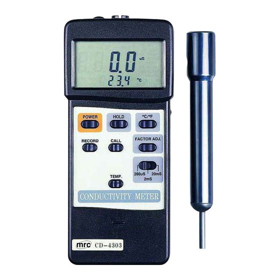
CODUCTIVITY METER
Model : CD-4303
Your
purchase
of
this
PRESSURE METER marks a
step forward for you into
the
field
of
precision
measurement.
Although
this PRESSURE METER is a
complex
and
delicate
instrument,
its
durable
structure will allow many
years of use if proper
operating techniques are
developed.
Please
read
the following instructions
carefully and always keep
this manual within easy
reach.
OPERATION MANUAL
3, Hagavish st. Israel 58817 Tel: 972 3 5595252, Fax: 972 3 5594529
mrc@mrclab.com
MRC.2.18
Advertisement

Related Manuals for MRC CD-4303


Summary of Contents for MRC CD-4303
- Page 1 CODUCTIVITY METER Model : CD-4303 Your purchase this PRESSURE METER marks a step forward for you into field precision measurement. Although this PRESSURE METER is a complex delicate instrument, durable structure will allow many years of use if proper operating techniques are developed.
-
Page 2: Table Of Contents
TABLE OF CONTENTS 1. FEATURES..............1 2. SPECIFICATIONS............2 2-1 General Specifications..........2 2-2 Electrical Specifications.......... 3 3. FRONT PANEL DESCRIPTION........4 Display..............4 Power Off/On button.......... 4 Data Hold Button..........4 button............4 ℃ ℉ LCD Contrast Adjust........... 4 Memory "Record"... -
Page 3: Features
1. FEATURES * Innovative feature with built-in automatic temperature compensation values adjustable between 0 to 5.0% per ℃ * Selecting "0% per " of Temp. Coefficient Adjust, allows ℃ you to take uncompensated conductivity readings. * Wide automatic temperature compensation range from 0 to 50 ℃... -
Page 4: Specifications
2. SPECIFICATIONS 2-1 General Specifications Circuit Custom one-chip microprocessor LSI circuit. Display Dual function display, 13 mm(0.5") Super large LCD display with contrast adjustment for best viewing angle. Measurement Conductivity : 3 ranges 199.9 uS, 1.999 mS, 19.99 mS. Temperature: 0 - 60 / 32 - 140 ℃... -
Page 5: Electrical Specifications
Weight 350 g/0.77 LB (included batteries) Size Main instrument: 180 x 72 x 32 mm(7.1 x 2.8 x1.3 inch). Probe : Round, 22 mm Dia. x 120 mm length. Accessories Instruction manual......1 PC. Included Sensor probe......1 PC. carrying case......1 PC. 2-2 Electrical Specifications(23±... -
Page 6: Front Panel Description
3. FRONT PANEL DESCRIPTION Fig. 1 3-1 Display 3-9 Range Select Switch 3-2 Power Off/On button 3-10 Temp. Coefficient 3-3 Data Hold Button Button button 3-11 Battery Compartment/ ℃ ℉ 3-5 LCD Contrast Adjust Cover 3-6 Memory "Record" 3-12 Input Socket Button 3-13 RS-232 Output 3-7 Memory "Call"... -
Page 7: Temp. Compensation Button
4. MEASURING PROCEDURE 4-1 Conductivity measurement (1) Push the "Power Off/On Button"(3-2, Fig. 1) to power the instrument. (2) The instrument will default to 2% per Temperature ℃ Compensation factor. The meter has built-in Automatic Temperature Compensation adjustable between 0 to 5% ℃... - Page 8 (4) Immerse the "Conductivity Electrode "(3-15, Fig. 1) into the solution, up to the immersion level. (5) During the measurement, the lower LCD Display will show the temperature of the solution. * Push the " / Button"(3-4, Fig. 1) to change ℃...
- Page 9 (c) Push the "CALL Button" once more, the "AVG" symbol with the average values will appear on the LCD display. (d) To de-activate the Data Record function, Press the "Record Button" (3-6, Fig. 1) once again. All associated anunciators will disappear from the display.
-
Page 10: Additional Features
5. ADDITIONAL FEATURES (a) The instrument has built-in "Auto Power Shut-off" in order to prolong battery life. The meter will switch off automatically if none of the buttons are pressed within 10 min. To de-activate this feature, Select the memory record function during measurement, by pressing the "RECORD"... - Page 11 7. RS232 PC INTERFACE The instrument features an RS232 output via 3.5 mm Terminal ( 3-13, Fig. 1). The connector output is a 16 digit data stream which can be utilized to the user's specific application. An RS232 lead with the following connection will be required to link the instrument with the PC serial input.
-
Page 12: Battery Replacement
D11 & D12 Anunuciator for Upper Display 01 =℃ 13 = uS 02 =℉ 14 =mS Anunuciator for Lower Display 0 = No Symbol 1 =C 2 = F Reading Polarity for the Display 0 = Both upper & lower display value are "+". 1 = Upper "-", Lower "+".
Need help?
Do you have a question about the CD-4303 and is the answer not in the manual?
Questions and answers