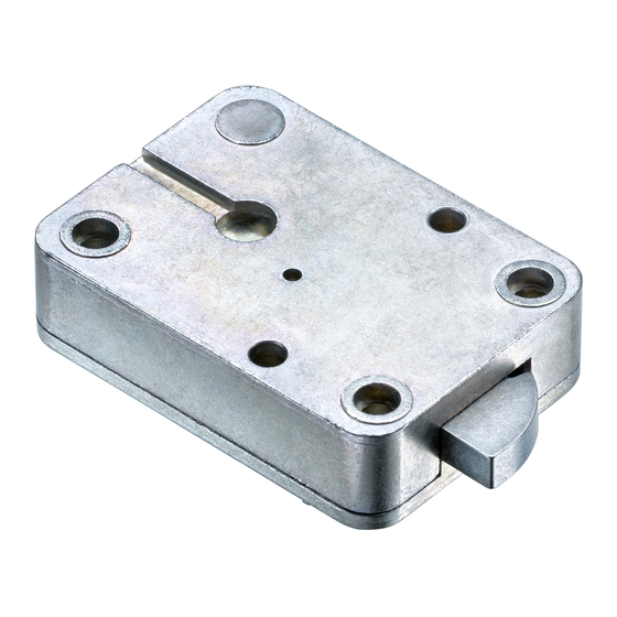
Wittkopp Primor 1000 Installation Instructions Manual
Hide thumbs
Also See for Primor 1000:
- Installation instructions manual (24 pages) ,
- Installer manual (6 pages)
Table of Contents
Advertisement
Quick Links
Installation instructions
Primor 1000
Content
1 General instructions �������������������������������������������������� 2
1.1 Liability notes ��������������������������������������������������������� 2
2 Lock installation ������������������������������������������������������ 2
2.1 Installing the lock ������������������������������������������������������ 2
2.2 Input unit installation ��������������������������������������������������� 3
2.3 Connection input unit/lock ���������������������������������������������� 3
2.4 Functional test ��������������������������������������������������������� 3
3 Installation examples/input unit �������������������������������������� 4
4 Installation input unit RO ��������������������������������������������� 5
4.1 Installation overview ��������������������������������������������������� 5
4.2 Axis length calculation �������������������������������������������������� 5
4.3 Installation of fixing ring ������������������������������������������������ 6
4.4 Mounting the input unit RO ��������������������������������������������� 6
4.4.1 Cable guidance input unit RO (turnable) �������������������������������� 7
4.5 Installation input unit RO (fixed) ������������������������������������������ 7
5 Installation input unit FL (fixing on the inside) ���������������������������� 8
5.1 Installation input unit FL (fixing from the front) ����������������������������� 9
5.2 Installation battery compartment ����������������������������������������� 9
6 Installation input unit FS ���������������������������������������������10
6.1 Cable guidance input unit FS �������������������������������������������11
© Carl Wittkopp GmbH - Errors and omissions excepted
Installation instructions no. 9999-118-1
Advertisement
Table of Contents

Summary of Contents for Wittkopp Primor 1000
-
Page 1: Table Of Contents
5.1 Installation input unit FL (fixing from the front) ����������������������������� 9 5.2 Installation battery compartment ����������������������������������������� 9 6 Installation input unit FS ���������������������������������������������10 6.1 Cable guidance input unit FS �������������������������������������������11 © Carl Wittkopp GmbH - Errors and omissions excepted Installation instructions no. 9999-118-1... -
Page 2: General Instructions
Installation instructions Primor 1000 1 General instructions • Please read the operating instructions carefully, before activating the lock. 1.1 Liability notes • The mounting of the electronic lock with input unit has to be carried out according to the installation instruction. -
Page 3: Input Unit Installation
Installation instructions Primor 1000 2.2 Input unit installation (see page 5) 2.3 Connection input unit/lock • Connect the plug from/to the input unit into the outer plug position on the lock and check fixation. To loose the plug, care- fully lift and pull out. -
Page 4: Installation Examples/Input Unit
Installation instructions Primor 1000 3 Installation examples/input unit Input unit RO (tur- nable) as boltwork actuator p. 5 Input unit RO (fixed) p. 7 Input unit FL fixing on the inside/ fixing on the outside with external battery com- partment p. -
Page 5: Installation Input Unit Ro
Installation instructions Primor 1000 4 Installation input unit RO Fig. 4: Dimensions input unit RO 4.1 Installation overview Fixing ring for input unit Cylinder screws M4 x 10 Connection axis for turnable input unit Connection cable Input unit Fig. 5: Explosion diagram Primor RO 4.2 Axis length calculation... -
Page 6: Installation Of Fixing Ring
Installation instructions Primor 1000 4.3 Installation of fixing ring • In order to install the fixing ring 4 threaded holes M4 and 1 drilling with max. Ø 11.4 mm/min. Ø 10.5 mm have to be drilled into the safe door. When mounting the fixed input unit RO, a door hole drilling of Ø 9mm is enough. -
Page 7: Cable Guidance Input Unit Ro (Turnable)
Installation instructions Primor 1000 4.4.1 Cable guidance input unit RO (turnable) • Lead the connection cable with the plug through the connection axis. • Lead the connection cable with the plug through the input unit. • Plug the connection axis into the input unit from behind and adjust the input unit to the locked electronic lock/boltwork. -
Page 8: Installation Input Unit Fl (Fixing On The Inside)
Installation instructions Primor 1000 5 Installation input unit FL (fixing on the inside) External battery compartment Fixing position for screws M5 Centre of drilling identical for front and inside fixing Fixing position for screws M5 Emergency power supply Cable opening Fig. -
Page 9: Installation Input Unit Fl (Fixing From The Front)
Installation instructions Primor 1000 5.1 Installation input unit FL (fixing from the front) External battery compartment Fixing position for screws M3 Centre of drilling identical for front and inside fixing Fixing position for screws M3 Cable opening Emergency power supply Fig. -
Page 10: Installation Input Unit
Installation instructions Primor 1000 6 Installation input unit FS Fixing position for screws M5 Fig. 14: Installation dimensions input unit FS Cable opening • In order to fix the input unit to the door, 2 threaded holes M5 have to be drilled into the front of the door. -
Page 11: Cable Guidance Input Unit
Installation instructions Primor 1000 6.1 Cable guidance input unit FS The connection cables have to be installed according to the figures: Fixing screws M5 bottom of case Connection cable (input unit - lock) Battery clip Lead connection cable underneath the clip Folding unit Fig. - Page 12 Installation instructions Primor 1000 09.11.2012...


Need help?
Do you have a question about the Primor 1000 and is the answer not in the manual?
Questions and answers