Table of Contents
Advertisement
Quick Links
Advertisement
Table of Contents

Related Manuals for Supermicro SC-830W


Summary of Contents for Supermicro SC-830W
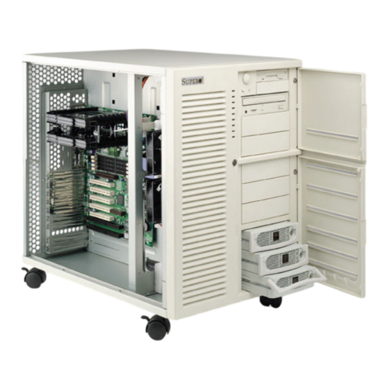
- Page 1 SC-830W CHASSIS SC-820W CHASSIS USER’S MANUAL Revision 1.1...
-
Page 2: Chassis Specifications
Chapter 1 SC830W/SC820W CHASSIS I. Chassis Specifications Dimensions: 380 x 505 x 570 mm ( W x H x D) A. Drive bay: 5.25” x 9, 3.5” x 2 B. 9 expansion slots C. lockable side door and front door D. -
Page 3: Installation Procedures
2. Installation Procedures To Open the Side Doors Please locate 4 holes and a lock on the motherboard sides of chassis. Unscrew the four screws on the side door, and the door will be unlocked. Move the doors slightly upward to open the door. Both side doors are unlocked by default. - Page 4 To Attach the Black Rubber Standoffs to the Inside Motherboard Tray to Function as Shock Absorbers. To prevent the motherboard from being damaged by impact, please peel off the double-sided tape of the rubber standoffs and attach the black rubber standoffs on the motherboard tray at the locations under the CPU and PCI slots.
- Page 5 To Install IDE , Floppy and SCSI Cables A. The chassis has eight cable access holes to enhance cable organization and to optimize airflow in the chassis. B. Locate eight cable holes inside the chassis. Route the cables through the closest cable access holes to the best organize the cables and to increase airflow in the chassis.
- Page 6 To Adjust Airflow Directions Two deflectors are designed to improve air circulation in the chassis. Loosen and tighten the screws on the deflectors to redirect the airflow in the chassis. If needed, the deflectors also can be removed. LED Connections LED Indicators on the Front Panel LED Definitions: 1.
- Page 7 Switches: 1. POWER: Power Switch 2. ALARM: ACPI Sleep Switch 3. RESET: Reset Switch Front Panel LED PCB Pin Assignments JP4 header 1 Power LED (Green) + 3 X Key 4 Fan Fail LED (Red) + 5 Power LED (Black) 6 Fan Fail LED Ground (black) 7 Hard drive LED (Yellow) + 8 Power Fail LED(Red) +...
-
Page 8: Chapter 2: Power Supply
CHAPTER 2: POWER SUPPLY 1. Installation: Hot-Swap procedures Please refer to the following procedures should either one of your power supply units is found defective. A) Locate the defective power supply by examining the individual LED on the module, or the LED on the system front panel. -
Page 9: Power Supply Features
2. Power Supply Features Hot-Swappable capability Internal ORing diode for Redundancy Operation Dual AC input for Redundancy safety Power fault alarm system Fan rail with noise decreasing function Standard PC connection/wiring interface Meet the up-to-date ATX specification Easy operating and maintain MTBF (Demonstrated) greater than 100,000 hours 3. - Page 10 Power On P1-PIN #14 PS-ON Power Switch P1-PIN #14 PS-ON 3.5 +5V SB The +5VSB output is always on (+5V Standby) when AC power is applied and the power switch is turned on. The +5VSB line is capable of delivering at a maximum of 1.5A for PC board circuit to operate.
- Page 11 3.8 Protection 3.8.1 Over Power Protection This power supply shut down all DC outputs when the outputs are overloaded to the limit. The power supply logic shall latch into the off state, the power supply shall return to the normal operation only after the fault has been removed, and the PS-ON, or AC input, has been cycled OFF/ON with a minimal OFF time of 1 second.
- Page 12 3.9 DC Output connectors 20 PIN (For ATX motherboard Main Power Connector.) Connector: Molex 39-01-2200 or approved equivalent. Signal 18AWG Wire 18AWG Wire Signal Orange +3.3VDC +3.3VDC Orange BRN. +3.3V default sense Blue -12VDC +3.3VDC Orange Black Black Green PS-ON +5VDC Black Black...
- Page 13 3.10 Temperature Operating Ambient: 50 to 122 °F ( 0 to 50 °C ). Derate Linearly to 50% at 70 °C Non-Operating Ambient: -4.0 to 140 °F ( -20 to 60°C ) 3.11 Relative Humidity Operating 20 to 90 % non-condensing at 104°F ( 40 °C ). Non-Operating 5 to 95 % non-condensing at 122°F ( 50°C ).
-
Page 14: Questions And Answers
4. Questions and Answers Q1. The system (Server, RAID etc.) does not work, neither does the PS. a) ATX or AT?!: The power supply with the ATX form factor is supposed to connect with the motherboard 20- pin ATX main power. So, please check the configuration and make sure the I/O switch is on. When you use the RAID or AT system, please check all connections. - Page 15 A device that you’ve installed requires the same resource as another device.(For example, a conflict occurs when two adapters try to write to the same address space.) b) The serverboard doesn’t come with the CPU, if the CPU is PIII 600MHZ, but the maximum allowed for the serverboard is 500MHZ.
Need help?
Do you have a question about the SC-830W and is the answer not in the manual?
Questions and answers