EKOM DK50 2V/50 Installation, Operation & Maintenance Manual
Oil-free
Hide thumbs
Also See for DK50 2V/50:
- Installation, operation and maintenance manual (84 pages) ,
- User manual (164 pages) ,
- User manual (204 pages)
Table of Contents
Advertisement
Quick Links
Advertisement
Chapters
Table of Contents

Related Manuals for EKOM DK50 2V/50


Summary of Contents for EKOM DK50 2V/50
- Page 1 DK50 2V/50 INSTALLATION, OPERATION AND MAN TENANCE MANUAL...
-
Page 2: Table Of Contents
DK50 2V/50 CONTENTS IMPORTANT INFORMATION ......................... 3 1. CE MARKING ..........................3 2. WARNINGS ..........................3 3. ALERT NOTICES AND SYMBOLS .................... 4 4. STORAGE AND TRANSPORT ....................4 5. TECHNICAL DATA ........................5 ... -
Page 3: Important Information
DK50 2V/50 IMPORTANT INFORMATION 1. CE MARKING Products labeled with the CE mark of compliance meet the safety guidelines (93/42/EEC) of the European Union. 2. WARNINGS 2.1. General warnings This Installation, Operation and Maintenance Manual is a part of the appliance and must be kept with the compressor. -
Page 4: Alert Notices And Symbols
DK50 2V/50 3. ALERT NOTICES AND SYMBOLS In the Installation, Operation and Maintenance Manual and on packaging and product, the following labels or symbols are used for important information: Attention, see instructions for use Caution, risk of electric shock Consult instructions for use... -
Page 5: Technical Data
DK50 2V/50 5. TECHNICAL DATA DK50 2V/50 DK50 2V/50S Nominal voltage / 230 / 50 230 / 50 frequency 3x400/50 3x400/50 V / Hz Efficiency of compressor at over-pressure 6 bar Lit.min Efficiency of compressor with dryer at over- pressure 6 bar Lit.min... -
Page 6: Product Description
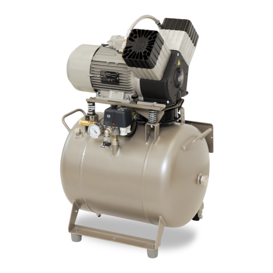
Compressors models are designed for the following uses: Dental compressors DK50 2V/50 - are designed for independent placement of the compressor in any area. Dental compressors DK50 2V/50/M - are designed for independent placement of the compressor in any area and feature a membrane dryer. - Page 7 DK50 2V/50 Fig.1 - Compressor Compressor motor Air tank Check valve Pressure switch Safety valve Manometer Condenser outlet Input filter Dryer Solenoid valve Cooler Micro-filter Filter Compressor fan Wheels Check valve Stopper Bottle Magnetic bottle holder Pulling system Wall stopper...
-
Page 8: Installation
DK50 2V/50 Fig.3 - Box INSTALLATION 8. USE The appliance must be installed and operated in a dry, well ventilated and dust-free area where ambient temperature is within the range of +5°C to +40°C and relative air humidity does not exceed 70%. Otherwise, failure-free operation of the compressor cannot be guaranteed. -
Page 9: Installation
Handling Fig.4 Unpacking Dental compressor DK50 2V/50, DK50 2V/50/M (Fig.4) After removing all packaging material, place the product on the floor and remove stabilization parts Y (Detail A). Connect output hose with end-piece to the appliance. Plug the mains cord plug into a socket. - Page 10 DK50 2V/50 In case of disassembling the compressor it is necessary to disconnect the connector of soundproofing box by using the screwdriver. Fig.5) Fig.5 Dental compressor in DK50 2V/50S/M, (Fig.3, Fig.4) After removing all packaging material, place the product on the floor and remove stabilization parts Y (Detail A).
-
Page 11: Wiring Diagrams
DK50 2V/50 10. WIRING DIAGRAMS 1/N/PE ~ 230V 50..60Hz * - only for 10 bar 1/N/PE ~ 230V 50..60Hz ELECTRIC OBJECT 1ST CAT. ELECTRIC OBJECT 1ST CAT. TYPE B TYPE B p > 0000 p > 0000 40°C 40°C * - only for 10 bar 40°C... - Page 12 DK50 2V/50 3/N/PE ~ 400/230 V 50 Hz 3/N/PE ~ 400/230 V 50 Hz MAINS TN-S [TN-C-S] MAINS TN-S [TN-C-S] ELECTRIC OBJECT 1ST CAT. * - only for 10 bar ELECTRIC OBJECT 1ST CAT. TYPE B TYPE B 150°C 150°C p >...
-
Page 13: Pneumatic Diagram
DK50 2V/50 11. PNEUMATIC DIAGRAM DK50 2V/50/M DK50 2V/50 Input filter Compressor motor Compressor Fan Solenoid valve Safety valve Check valve Pressure switch Air tank Manometer 10 Cooler 11 Cooler Fan 12 Dryer 13 Filter 14 Microfilter 15 Bottle 02/2016... -
Page 14: First Operation
DK50 2V/50 12. FIRST OPERATION (Fig.8) Make sure that all stabilizers used during transport were removed. Check that all pressurized air line connections are secure. Connect to the mains. Start compressor at pressure switch (2) by turning switch (3) to position “I.“... -
Page 15: Switching The Compressor On
DK50 2V/50 13. SWITCHING THE COMPRESSOR ON (Fig.8) Switch on the compressor at the pressure switch (2) by turning the knob (3) to position “I.”, (for compressor in the box switch (24) Fig.3 on the front part of the compressor box),The compressor sends pressurized air to the air tank. - Page 16 DK50 2V/50 TO ENSURE THAT THE COMPRESSOR WORKS CORRECTLY, PERFORM THE FOLLOWING MAINTENANCE TASKS AT REGULAR INTERVALS (CHAPTER 14).: 15.1. Condensation drain valve Compressors (Fig.9) During regular use, release condensation from the pressure tank. Switch off the compressor at the mains. Reduce air pressure in the appliance to max.
-
Page 17: Storage
DK50 2V/50 15.4. Replace the filter element (Fig.11) Loosen a safety-catch (1) on a filter regulator by pulling it down. Turn the container slightly (2) and pull out. Unbolt the filter holder (3). Change the filter bed (4), bolt the filter holder. -
Page 18: Solving Problems
DK50 2V/50 19. SOLVING PROBLEMS Caution! Before proceeding, depressurize the air tank to zero and disconnect the appliance from the mains. For permanently high efficiency of drying, it is necessary to maintain the whole appliance, and mainly ventilator clean – regularly clean the surface of ventilator and cooling fins of ... - Page 19 ANNEX TO NP- DK50 2V/50 Annex is integral part of Instructions for use 406201005-002 DK50 2V/50 406202005-001 DK50 2V/50S 4062010B5-002 DK50 2V/50/M 4062020B5-001 DK50 2V/50S/M 406201005-003604021607604021607 DK50 2V/50 4062010B5-003 DK50 2V/50/M CONTENTS TECHNICAL DATA .............................
-
Page 20: Technical Data
TECHNICAL DATA (Replaced - not apply chapter 5 in NP DK50 2V/50) DK50 2V/50/M DK50 2V/50S DK50 2V/50 DK50 2V/50S/M Nominal voltage / frequency 230 / 50 230 / 50... - Page 21 Replaced - not apply chapter 5 in NP DK50 2V/50) DK50 2V/50 DK50 2V/50/M 406201005-003 4062010B5-003 Nominal voltage / frequency 230 / 50 230 / 50 V / Hz Efficiency of compressor at over-...
-
Page 22: Function
13. Filterregulator 14. Botlle 15. Holder 16. Plug Fig. A Annex to NP DK50 2V50-Absolute Air-7_02-2016 EKOM spol. s r.o. + 421 33 7967 255 Priemyselná 5031/18 + 421 33 7967 223 112000182-000 SK - 921 01 PIEŠŤANY e-mail: ekom@ekom.sk... - Page 23 14. Botlle 15. Holder 16. Plug 17. Autodrain Fig. B Annex to NP DK50 2V50-Absolute Air-7_02-2016 EKOM spol. s r.o. + 421 33 7967 255 Priemyselná 5031/18 + 421 33 7967 223 112000182-000 SK - 921 01 PIEŠŤANY e-mail: ekom@ekom.sk...
- Page 24 DK50 2V/50/M - 4062010B5-002 DK50 2V/50S/M - 4062020B5-001 Compressor motor Air tank Check valve Pressure switch Safety valve Manometer Input filter Air output Solenoid valve Quick coupling Plug Hose of manometer...
- Page 25 12. Hose of manometer (applies for connecting to the box ) 13. Regulator 14. Hour meter Fig. D Annex to NP DK50 2V50-Absolute Air-7_02-2016 EKOM spol. s r.o. + 421 33 7967 255 Priemyselná 5031/18 + 421 33 7967 223 112000182-000 SK - 921 01 PIEŠŤANY...
- Page 26 DK50 2V/50/M - 4062010B5-003 Compressor motor Air tank Check valve Pressure switch Safety valve Manometer Input filter Air output Solenoid valve Quick coupling Plug Hose of manometer Cooler Dryer Control panel...
-
Page 27: Wiring Diagrams
Glowlamp Thermo switch of box 40°C DK50 2V/50S - 406202005-001 Annex to NP DK50 2V50-Absolute Air-7_02-2016 EKOM spol. s r.o. + 421 33 7967 255 Priemyselná 5031/18 + 421 33 7967 223 112000182-000 SK - 921 01 PIEŠŤANY e-mail: ekom@ekom.sk... - Page 28 Glowlamp 40°C DRYER 9. 3. 2012 DK50 2V/50S/M - 4062020B5-001 Annex to NP DK50 2V50-Absolute Air-7_02-2016 EKOM spol. s r.o. + 421 33 7967 255 Priemyselná 5031/18 + 421 33 7967 223 112000182-000 SK - 921 01 PIEŠŤANY e-mail: ekom@ekom.sk...
- Page 29 Solenoid valve Contactor Terminal Hour meter - 406201005-003 DK50 2V/50 Annex to NP DK50 2V50-Absolute Air-7_02-2016 EKOM spol. s r.o. + 421 33 7967 255 Priemyselná 5031/18 + 421 33 7967 223 112000182-000 SK - 921 01 PIEŠŤANY e-mail: ekom@ekom.sk...
- Page 30 Calculated when equipment is switched on 8,000 hour maintenance Calculated using the number of operating hours Annex to NP DK50 2V50-Absolute Air-7_02-2016 EKOM spol. s r.o. + 421 33 7967 255 Priemyselná 5031/18 + 421 33 7967 223 112000182-000 SK - 921 01 PIEŠŤANY...
-
Page 31: Maintenance
Replace 2 x desiccant cartridges, gasket 24, 000 hours (or 6 years) service seals and all valves. Annex to NP DK50 2V50-Absolute Air-7_02-2016 EKOM spol. s r.o. + 421 33 7967 255 Priemyselná 5031/18 + 421 33 7967 223 112000182-000 SK - 921 01 PIEŠŤANY... -
Page 32: Parts List
Wall stopper 023000276-000 Transport mechanism 603021540-000 Set for discharge of condensate 604011122-000 Push-in jumper 033190119-000 Lockout-cap 062000759-000 ..................4062020B5-001 DK50 2V/50 S/M Installation, Operation and Maintenance NP-DK50 2V/50 Manual Fuse T0,8A/35 038100006-000 Wall stopper 023000276-000 Transport mechanism 603021540-000 Bottle with magnetic holder... - Page 33 NP-DK50 2V50-7_02-2016 MD 112000166-000...
Need help?
Do you have a question about the DK50 2V/50 and is the answer not in the manual?
Questions and answers