
Related Manuals for Rotex RKHWMX300C


Summary of Contents for Rotex RKHWMX300C
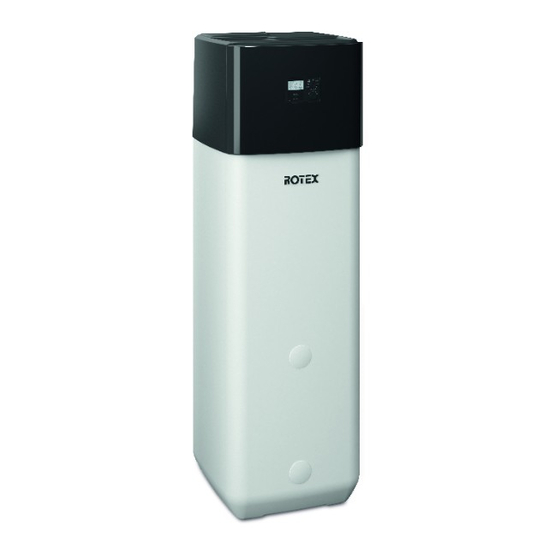
- Page 1 For certified companies ROTEX HPSU monobloc compact Installation and maintenance instructions Solar storage tank with heating controller For types RKHWMX300C RKHWMX500C RKHWMXB300C RKHWMXB500C Edition 09/2017...
-
Page 3: Table Of Contents
12 List of keywords ..... . 71 4.5.14 Connecting a ROTEX HP convector ... .31 4.5.15 Connecting switching contacts (AUX outputs) . -
Page 4: General Information
– RoCon mb controller operating instructions – Outdoor unit for ROTEX HPSU monobloc compact: the respective installation and operating instructions. – On connection of a ROTEX solar system: the respective installation and operating instructions. – On connection of a ROTEX HP convector: the respective installation and operating instructions. -
Page 5: Safety
2.2 Avoiding danger Special warning signs The ROTEX HPSU monobloc compact is built Some types of danger are represented by according to the state-of-the-art and the recog- special symbols: nised technical rules. However, improper use... -
Page 6: Intended Use
Not all the equipment mentioned here is offered in some countries because of the various different country-specific connection conditions. Electrical installation must only be carried out Tab. 2-1 Permissible combinations of ROTEX HPSU monobloc by specialist personnel with electrical compact solar storage tanks with heating controller and... -
Page 7: Site Of Installation
2.4.5 Requirements for the heating water For safe and fault-free operation, the installation Observe the relevant regulations of technology location of the ROTEX HPSU monobloc compact to prevent creation of corrosion products and de- must meet certain criteria. Information on this posits. -
Page 8: Product Description
3.1.1 Exterior of the device and interior structure RKHWMX(B)300C 3UVB1 V,BH 3UVB1 RoCon B1 3UVB1 3UV DHW 24 / 11 Fig. 3-1 RKHWMX(B)300C design and components (exterior view and interior structure) Key names, see tab. 3-1 FA ROTEX HPSU monobloc compact • 09/2017... -
Page 9: Exterior Of The Device And Interior Structure Rkhwmx(B)500C
3.1.2 Exterior of the device and interior structure RKHWMX(B)500C 3UVB1 V,BH 3UVB1 RoCon B1 3UVB1 3UV DHW 24 / 11 Fig. 3-2 RKHWMX(B)500C design and components (exterior view and interior structure) Key names, see tab. 3-1 FA ROTEX HPSU monobloc compact • 09/2017... -
Page 10: Upper Side Of The Device
Product description 3.1.3 Upper side of the device 3UV DHW 23 35 3UV DHW V,BH (34) (34) 3UV DHW 3UVB1 Fig. 3-3 RKHWMX(300/500)C design and components (upper side of the device) FA ROTEX HPSU monobloc compact • 09/2017... - Page 11 Fill level indicator (storage tank water) Diaphragm expansion vessel connection Controller housing with electr. connector block Holding burls for protective cover RPS4 Optional: ROTEX solar control and pump unit Tab. 3-1 Legend for fig. 3-1 to fig. 3-3 FA ROTEX HPSU monobloc compact • 09/2017...
-
Page 12: Set-Up And Installation
Work on the ROTEX HPSU monobloc compact (such as e.g. installation, repair, connection and ini- tial commissioning) must only be carried out by persons who are authorised, who have successfully completed qualifying technical or vocational training for the respective activity and who have taken part in advanced training sessions recognised by the relevant responsible authority. -
Page 13: Dimensions And Connections
Outdoor unit water inlet connection Cold water Solar feed (type …(B) only) Hot water Solar return (type …(B) only) Heating flow Heating return flow Front Outdoor unit water outlet connection Rear Fig. 4-1 RKHWMX(B)300C connections and dimensions FA ROTEX HPSU monobloc compact • 09/2017... -
Page 14: Rkhwmx(B)500C
Outdoor unit water inlet connection Cold water Solar feed (type …(B) only) Hot water Solar return (type …(B) only) Heating flow Heating return flow Front Outdoor unit water outlet connection Rear Fig. 4-2 RKHWMX(B)500C connections and dimensions FA ROTEX HPSU monobloc compact • 09/2017... -
Page 15: Scope Of Delivery
(>80 °C) (e.g. electrical safety overflow Plug bracket Spanner Venting tube heater, oil heater, chimney) and the material Cover drain hose to be combusted. Fig. 4-3 Contents of bag of accessories FA ROTEX HPSU monobloc compact • 09/2017... - Page 16 Handle Threaded piece Cover screen Fig. 4-4 Installing the handles Install the ROTEX HPSU monobloc compact at the installa- tion site. – Recommended clearances (fig. 4-5): From the wall: (s1) 100 mm, (s2) 500 mm. From the ceiling (X): 1200 mm, at least 480 mm.
-
Page 17: Removing The Cover And Thermal Insulation
10 Nm 1200 mm Fig. 4-7 Producing the cover cut-out Fig. 4-5 Installation (shown on RKHWMX(B)500C with installation of the optional backup heater) Fig. 4-8 ROTEX HPSU monobloc compact without protective cover FA ROTEX HPSU monobloc compact • 09/2017... -
Page 18: Water Connection
Fig. 4-10 Removing the bottom thermal insulation The thermal insulation is installed in reverse order. 4.4 Water connection CAUTION! If the ROTEX HPSU monobloc compact is con- Fig. 4-9 Removing the top thermal insulation nected to a heating system with steel pipes,... -
Page 19: Aligning The Connections Of The Heating Supply And Return
A diaphragm expansion vessel suitably sized and preset for the Always place O-rings on the part to be heating system must be connected to the ROTEX HPSU mono- inserted after a plug connection has been bloc compact. There may not be any hydraulic blocking ele- ments between the heat generator and the diaphragm expan- removed or before it is installed. -
Page 20: Connecting Hydraulic Lines
Prerequisite: optional accessories (e.g. solar, backup heater) are Slide the retaining plate between the manifold and its horizon- mounted on the ROTEX HPSU monobloc compact as specified tal mounting and insert the manifold (fig. 4-12, item F) back in the enclosed instructions. -
Page 21: Installation Of The Db Connection Kit ( 14 15 90)
Connect the discharge fitting on the cover (fig. 3-3, item 30) to the waste water installation with the enclosed hose section. Connection for supply (red) Connection for return (blue) Fig. 4-16 P connection kit for B device types FA ROTEX HPSU monobloc compact • 09/2017... -
Page 22: Electrical Connection
For this reason, these lines need to have a continuous use temperature of 90 °C. For the following connections, use only cables with a long-term use temperature 90 °C: – Optional: electric backup heater (BUxx) FA ROTEX HPSU monobloc compact • 09/2017... -
Page 23: Rotex Hpsu Monobloc Compact Overall Connection Diagram
See tab. 4-2 and tab. 4-3 for an explanation of the sym- connection diagram bols and abbreviated designations in this chapter. Fig. 4-17 Overall connection diagram - for electrical connection during device installation FA ROTEX HPSU monobloc compact • 09/2017... -
Page 24: Position Of The Printed Circuit Boards
Controller control panel Controller cover Fig. 4-18 Overview of printed circuit boards (inside housing) 4.5.3 RTX-EHS printed circuit board connection diagram Fig. 4-19 RTX-EHS printed circuit board (backup heater) - see chap. 4.5.10 FA ROTEX HPSU monobloc compact • 09/2017... -
Page 25: Rocon Bm2C Printed Circuit Board Connection Diagram
The outdoor unit and optional accessories must be connected to the ROTEX HPSU monobloc compact controller separately. To do this, the cover of the ROTEX HPSU monobloc compact must be removed (see chap. 4.3) and the controller housing must be opened if necessary (see chap. -
Page 26: Opening The Controller Housing And Establishing Electrical Connections
The operating mode has an effect on the direct circuit of the ROTEX HPSU monobloc compact as well as all other heating cir- cuits connected to this device as an option. -
Page 27: External Requirement Request (Eba)
ROTEX solar system. 4.5.9 External requirement request (EBA) By connecting the EBA switching contact to the ROTEX HPSU monobloc compact (fig. 4-31) and corresponding parameterisa- tion in its RoCon mb controller, an external switching contact can be used to generate a heat request. - Page 28 Contact with a damaged backup heater con- nection cable can result in an electric shock and therefore life-threatening injuries and burns. Do not repair the backup heater's connection cable. Always replace the entire backup heater. FA ROTEX HPSU monobloc compact • 09/2017...
-
Page 29: Connecting An External Heat Generator
For heating support or as an alternative to an electric backup heater (see chap. 4.5.10), an external heat generator (e.g. gas- or oil-fired boiler) can be connected to the ROTEX HPSU mono- bloc compact. The heat supplied by the external heat generator must be fed to the unpressurised storage tank water in the ROTEX HPSU monobloc compact's hot water storage tank. -
Page 30: Connecting A Rotex Room Thermostat
Fig. 4-37 Connection with wireless room thermostat (RT-E = ROTEX RKRTR, 14 10 04) It is possible for the ROTEX HPSU monobloc compact to be con- nected to the RoCon M1 mixer module, which is operated using the RoCon mb electronic controller. -
Page 31: Connecting A Rotex Hp Convector
– If necessary, install and connect a 2-way valve (2UV) (HPC- 14 20 13) in the ROTEX HP convector. Set its con- Fig. 4-40 Connection of the ROTEX HP convector (min. 3) to the troller so that the 2-way valve (2UV) closes when no request ROTEX HPSU monobloc compact is available from this device. -
Page 32: Off-Peak Mains Connection (Ht/Nt)
> 15 W) must be suitable for a 100% on time. Switchover contact A-A1-A2 can be used e.g. to control the heat generators in bivalent heating systems consisting of a ROTEX HPSU monobloc compact and an oil-or gas-fired boiler. Exam- ples of hydraulic system integration are described in chapter 9. -
Page 33: Symbols And Key Names For Connection And Wiring Diagrams
RoCon U1 Room station Status output for "Cooling" operating mode RoCon UFH (RoCon UHF floor heating controller connection) Room thermostat (RKRTW) RT-E Receiver for wireless room thermostat (RKRTR) RTX-EHS Printed circuit board (backup heater) FA ROTEX HPSU monobloc compact • 09/2017... -
Page 34: Filling The System On The Water Side
Tab. 4-3 Key names for connection and wiring diagrams 4.6 Filling the system on the water side Fill the ROTEX HPSU monobloc compact only after completion of all installation work in the order shown below. 4.6.1 Checking the water quality and adjusting the... -
Page 35: Start-Up
The settings for optional components such as a room thermostat trained heating specialists. or ROTEX solar system must be carried out on the respective components. 5.1.1 Requirements CAUTION! –... -
Page 36: Setting Commissioning Parameters
If an outside temperature sensor is connected, set the parameter [Tamb Config] to "1". Set further commissioning parameters on the ROTEX HPSU monobloc compact controller depending on system require- ments. With glycol in the system, set the parameter [Glycol] to "1". -
Page 37: Checking The Minimum Flow
Close the valves and adjuster drives of all connected heat Any air present can escape via the automatic vent valve during distribution circuits. the air purge and the hydraulic circuit connected to the ROTEX Set "Heating" operating mode on the ROTEX HPSU HPSU monobloc compact is evacuated. -
Page 38: Re-Commissioning
"Off" again. 1. Check the cold water connection and, where necessary, fill the potable water heat exchanger. 2. Switch on the power supply to the ROTEX HPSU monobloc compact. 3. Wait for the start phase. FA ROTEX HPSU monobloc compact • 09/2017... -
Page 39: Taking Out Of Operation
Clamping piece on if there is a danger of frost. Tab. 6-1 Legend for fig. 6-1 to fig. 6-6 If the ROTEX HPSU monobloc compact is not needed for a long time, it can be temporarily decommissioned. Without solar system... -
Page 40: Draining The Heating Circuit And Hot Water Circuit
(see also fig. 6-5) and drain the water content of the storage tank. 6.1.2 Draining the heating circuit and hot water circuit Connect the drain hose to the KFE cock of the ROTEX HPSU monobloc compact. Fig. 6-3 Completing the KFE fill- Fig. -
Page 41: Final Shutdown
– the system or parts of the system are being dismantled and reassembled in another location. The ROTEX HPSU monobloc compact is designed to be environ- mentally friendly and easy to install so that the activities described above can be carried out in an efficient and environ- mentally friendly manner. -
Page 42: Service And Maintenance
4. If the ROTEX HPSU monobloc compact is operated in a bivalent, alternative system, switch off all heat generators and deactivate the bi-valence controller. 5. Visual inspection of the general condition of the ROTEX HPSU monobloc compact. -
Page 43: Filling, Topping Up The Storage Tank
13. Check the minimum flow (see chap. 5.1.5). With backup heater (BUxx): 14. Clean the plastic surface of the ROTEX HPSU monobloc At an outside temperature of < 12 °C and a storage tank tem- compact with soft cloths and mild cleaning solution. Do perature of <... -
Page 44: Filling, Topping Up The Heating System
Connect the filling hose with non-return valve (1/2") to the ROTEX HPSU monobloc compact. previously installed KFE cock. Fill the storage tank of the ROTEX HPSU monobloc compact After initial filling, check whether all electrical until water emerges at the connection (fig. 7-1, item 23) parts and connecting points are dry before that was connected as a safety overflow. -
Page 45: Filling, Topping Up Steps
KFE cock (fig. 7-2, item 2) and secure it against slipping off with a hose clamp. 2. Make sure that the automatic vent valve cap is open (fig. 5-3, item A). if not already installed in the heating system FA ROTEX HPSU monobloc compact • 09/2017... - Page 46 10. Set the rotary switch to the "Operating Mode" position and select "Heating". ROTEX After the start phase, the HPSU monobloc com- pact runs in hot water heating operation. 11. Constantly check the water pressure on the external pressure gauge during hot water heating mode, and top up water via the KFE cock (fig.
-
Page 47: Errors, Malfunctions And Messages
8.1 Recognising errors, correcting FA failure malfunctions The ROTEX HPSU monobloc compact's electronic controller: – signals an error by means of the background of the display lighting up red and shows an error code on the display (see Special Level tab. -
Page 48: Malfunctions
The parameter [SMART GRID] is active and the connections are set incorrectly. The electricity company has sent the peak Wait for the repeat off-peak rate signal which reacti- rate signal. vates the power supply. FA ROTEX HPSU monobloc compact • 09/2017... - Page 49 Thermal contactor (STB) on the backup heater (BUxx) Optional backup heater (BUxx) or alternative has triggered. Unlock. heater booster not cut in. Check parameters [Function Heating Rod], [BUH s1 power] and [BUH s2 power]. FA ROTEX HPSU monobloc compact • 09/2017...
- Page 50 Refrigerant quantity in the heating system too refrigerant circuit for leaks, repair and add refriger- low or too high. ant. If the refrigerant quantity is too high, recycle the refrigerant and refill the system with the correct quantity. FA ROTEX HPSU monobloc compact • 09/2017...
- Page 51 – Turn the red knob on the safety pressure relief Safety pressure relief valve is stuck. valve counterclockwise. If you can hear a rattling noise, the safety pressure relief valve needs replacing. Tab. 8-1 Possible malfunctions on the HPSU monobloc compact FA ROTEX HPSU monobloc compact • 09/2017...
-
Page 52: Error Codes
Check, replace. Initialisation after heat pump start failed. E8100 — Communication Electrical components Printed circuit board A1P (outdoor unit) defective. Check, replace. Temporary internal Not relevant for proper system operation. E9000 — — message FA ROTEX HPSU monobloc compact • 09/2017... - Page 53 Thermal contactor (STB) in the backup heater (BUxx) has triggered. Optional: STB backup E9009 Check and unlock position of STL. heater (BUxx) STB fault E9010 Software Thermal contactor activated (water temperature > 85 °C) FA ROTEX HPSU monobloc compact • 09/2017...
- Page 54 – Outlet temperature sensor R2T on the refrigerant compressor sor (hot gas sensor) R2T or connecting cable defective. Evaporator over- E9020 on the heat pump out- – Refrigerant compressor defective. temp door unit refrigerant Check, replace. compressor too high FA ROTEX HPSU monobloc compact • 09/2017...
- Page 55 Temperature sensor of fin heat exchanger R4T E9028 Aircoil sensor temp in the heat pump outdoor unit Fluid side temperature Fault cold sensor E9029 sensor R6T in the heat pump outdoor unit FA ROTEX HPSU monobloc compact • 09/2017...
- Page 56 – Wiring, poor contact. – Service valves in the heat pump outdoor unit not open. Check, eliminate cause, replace. If necessary, contact a ROTEX service technician. – Refrigerant compressor defective. – Inverter circuit board in the heat pump outdoor unit defective.
- Page 57 Configuration of printed circuit board A1P (outdoor unit) does not match the heat pump outdoor unit E9044 Replace printed circuit board A1P. If necessary, contact a ROTEX service technician. WW heating > 6 hours Check the heating element. Check whether the power supply meets the regulations. Check for frequency fluctuations.
- Page 58 Check whether the power supply meets the regulations. Check for frequency fluctuations. Check the outer inverter conductor plate. Check whether the current flow LED flashes at regular intervals. Check whether the correct replacement part has been installed. FA ROTEX HPSU monobloc compact • 09/2017...
- Page 59 Tab. 8-2 Fault codes on the HPSU monobloc compact controller Observe maximum temperature sensor tightening torque (see chap. 10.3 "Tightening torque"). Refer to the heat pump outdoor unit installation instruc- tions for information on components in the refrigerant circuit. FA ROTEX HPSU monobloc compact • 09/2017...
-
Page 60: Control And Configuration Of Dip Switches
Operation" function on the controller (see controller operating Accumulator instructions). Refrigerant compressor If the 3-way valves are intact, the ROTEX HPSU monobloc com- 4-way switch valve (—> heating, ····> cooling) pact switches to heating mode. The required inflow temperature Feed temperature sensor can be adjusted with the rotary switch. -
Page 61: Hydraulic System Connection
Hydraulic system connection Hydraulic system connection To avoid heat losses due to gravity flows, the ROTEX devices can be optionally equipped with plastic non- WARNING! return valves ( 16 50 70). These are suitable for maximum operating temperatures of 95 °C and for... - Page 62 Solar collector temperature sensor Solar return flow temperature sensor Solar flow temperature sensor Fan (vaporiser) Scalding protection VTA32 Observe notes on electrical connection (see chap. 4.5.11 and 4.5.15)! Tab. 9-1 Abbreviations on hydraulics plans FA ROTEX HPSU monobloc compact • 09/2017...
-
Page 63: Technical Data
Feed temperature (min./max.) for room heat- Cooling ing/cooling function Operating range °C 5 to 22 (min/max) Hot water prepara- Heating °C 25 to 80 tion (with BUxx) (min./max.) Audibility Noise level Sound pressure FA ROTEX HPSU monobloc compact • 09/2017... - Page 64 Number of individual lines in the connection cable including protective earth conductor. The cross-section of the individual lines is dependent on the current load, the length of the connection cable and the respective legal provisions. Tab. 10-1 RKHWMX(B)300C basic data FA ROTEX HPSU monobloc compact • 09/2017...
-
Page 65: Rkhwmx(B)500C
Feed temperature (min./max.) for room heat- Cooling ing/cooling function Operating range °C 5 to 22 (min/max) Hot water prepara- Heating °C 25 to 80 tion (with BUxx) (min./max.) Audibility Noise level Sound pressure FA ROTEX HPSU monobloc compact • 09/2017... - Page 66 Number of individual lines in the connection cable including protective earth conductor. The cross-section of the individual lines is dependent on the current load, the length of the connection cable and the respective legal provisions. Hot water storage tank charged just by heat pump without backup heater. Tab. 10-2 RKHWMX(B)500C basic data FA ROTEX HPSU monobloc compact • 09/2017...
-
Page 67: Characteristic Lines
Maximum sensor tightening torque =10 Nm. Water pressure Sensor resistance (NTC) Voltage Temperature Backup heater feed temperature sensor Fig. 10-3 Characteristic of pressure sensor (DS) ROTEX HPSU mono- V, BH bloc compact Fig. 10-1 Characteristics of feed temperature sensor t ROTEX V, BH HPSU monobloc compact 10.3 Tightening torque... -
Page 68: Circuit Diagram Rotex Hpsu Monobloc Compact
Technical data 10.4 Circuit diagram ROTEX HPSU monobloc compact Fig. 10-4 ROTEX HPSU monobloc compact circuit diagram - key, see tab. 4-3 FA ROTEX HPSU monobloc compact • 09/2017... -
Page 69: Notes
Notes 11 Notes FA ROTEX HPSU monobloc compact • 09/2017... - Page 70 Notes FA ROTEX HPSU monobloc compact • 09/2017...
-
Page 71: List Of Keywords
Initial commissioning ... . .35 Installation .....15 FA ROTEX HPSU monobloc compact • 09/2017...
Need help?
Do you have a question about the RKHWMX300C and is the answer not in the manual?
Questions and answers