Sign In
Upload
Manuals
Brands
Erbe Manuals
Medical Equipment
ICC 300 H-E
Erbe ICC 300 H-E Manuals
Manuals and User Guides for Erbe ICC 300 H-E. We have
1
Erbe ICC 300 H-E manual available for free PDF download: Service Manual
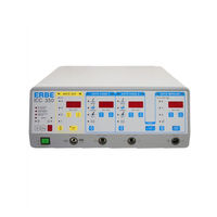
Erbe ICC 300 H-E Service Manual (267 pages)
Electrosurgical Units
Brand:
Erbe
| Category:
Medical Equipment
| Size: 3 MB
Table of Contents
Table of Contents
5
1 Test Programs and Adjustments
7
Test Programs
9
Calling up Test Program Mode
10
Exiting the Test Program Mode
10
Setting the Test Program Number
10
Starting and Finishing Test Programs
10
Basic Settings of the SETUP Parameters
11
Factory Setting
12
Front Panel of the ICC 200 (INT) after Starting up the Unit
12
Factory Programming
13
Front Panel of the ICC 200 (UL) after Starting up the Unit
13
Front Panel of the ICC 300 after Starting up the Unit
15
Front Panel of the ICC 350 after Starting up the Unit
16
FIXE Basic Setting
17
Switch off a Channel
17
Test Program No. 1
17
Test Program No. 2 - Call up and Display of the Error Memory
18
Test Program No. 3 - Test of All D-Flipflop Circuit Memories
19
Overview of the D-Flipflop Tests
20
Test Program No. 4 - Check of the Optical Signals on the Front Panel
21
Test Program No. 5 - Sound Control for All Available Sounds
22
Frequency Adjustment for Warning Tones
23
Designation of the Pcbs with Their Assigned Relays
24
Test Program No. 6 - Relay Test
24
Overview of the Relay Test Options
25
Test Program No. 7 - Setting the NESSY Version
26
Test Program No. 8 - Display of the Software Version and any Options
27
Test 9: Activating Display Programs to Display Measurement Values
28
Test Program 9 (Display Programs 1-12)
28
Display Programs Nos. 1–3
29
Display Programs Nos. 4–5
30
Display Program Nos. 5–7
31
Display Program No. 8
32
Measurement Values for Activation of the Sine-Wave Generator
32
Display Program No. 9
33
Display Programs Nos. 10–11
34
Contact Resistance at AUTO START, in Standby Operation
35
Contact Resistance for AUTO START, in Active Condition
35
Display Program No. 12 (Start)
35
Display Program No. 15
37
NESSY Transition Resistance in Stand-By-Operation and on Activation
37
Display Programs Nos. 13–22
38
Test Program No. 10 - Changing the Maximum Time Limit
39
Test Prog. 11 - Measurement Value Output for the Measurement Channels
40
Test Program No. 12 - Setting the FORCED Voltage
43
Pre-Information: Recommended Measuring Equipment
45
Test Program 16 (Adjustments, Measuring Equipment, Jumper)
45
Jumper on the Display Board
46
Where Are the Slots for the Jumpers?
46
Note Regarding ERROR 30
49
Test Program No. 16 - General Description
50
Test Program No. 16 - List of Individual Adjustments
51
Adjustment 1 - Power Supply Unit Phase Relationship
54
Adjustment 2 - Power Supply Unit Output Parameters
58
Adjustment 3 - Actuation Pulse Length HF Generator
62
Adjustment 4 - Phase Relationship HF Generator
66
Adjustment 5 - HF Generator Output Parameters
70
Adjustment 6 - HF Generator Output Parameters Amplified
74
Adjustment 7 - Phase Angle (Cos J)
78
Adjustment 8 - Spark Monitor
82
Adjustment 9 - NESSY Resistance Measurement
86
Adjustment 10 - HF Leakage Current Measurement
90
Adjustment 11 - Contact Monitor
94
Adjustment 12 - Pulse/Pause Length ST Output Stage
98
Adjustment 13 - LF Leakage Current Monitor (ICC 350 Only)
102
Adjustment of ZMK Neurotest and TUR Neurotest
105
Adjustment of Neurotest Board
106
Setting the Feedback Frequency of Output Current Measurement
106
General Information about the Self-Check
108
Performance Test on Output Error Monitoring
108
Performance Test on the Electronic Fuse
108
Testing the Constant-Current Source
108
Activation of the HF LED on the Remote Control
109
Adjustment of Remote Control for Neurotest
111
Adjustment of Remote Control for Neurotest
112
Setting the Feedback Frequency for Intensity Setting
112
Adjustment of Activation and Instrument Detection
115
Adjustment of Activation and Instrument Detection
116
Display of Instrument Number
116
Valid Instrument Number
116
Test Instructions for Program 12 MIC
118
Test Program No. 17 - Brightness Setting of the 7-Segment Displays
123
Test Program No. 23 - Changing the Delay Time with Auto Start
124
Changing the Delay Time for Auto Start
126
2 ERROR List
127
ERROR List V 4.X
129
Automatic Error Detection, Indication and Documentation
129
Troubleshooting for ICC Family Equipment
129
3 Circuit Description
137
Circuit Description
139
Motherboard
139
Limitation of the High Frequency Leakage Currents
140
Monitoring the High-Frequency Leakage Currents
141
Changeover between Flowing and Capacitance-Grounded Output
141
Footswitch Input Circuit
142
CPU Board
143
Low Voltage Supply
144
Voltage Regulator for +24 Volts
144
Voltage Regulation for +15 Volts
144
Voltage Regulation for – 15 Volts
144
Voltage Regulation for +5 Volts
145
Tone Generators for the Signal Tones
145
Measured Value Acquisition and Adjustment
146
The Contact Monitor
146
Actuation and Power Setting of the ST Output Stage
147
Actuation of the Power Module
147
Synchronization of the QK Output Stage
148
Hardware Electronic Safety Circuits
149
The Spark Control
149
Actuation of the QK Output Stage
150
QC Power Stage
152
Power Module UL
155
Serial Oscillating Circuit for the QC Power Stage
155
Generation of the Operating Voltage of the HF Generator
155
Power Module
156
Driver and Output Stage of the HF Generator
156
Output Circuit of the HF Generator
156
Measurement of Various Operating Parameters (Power Module)
156
ST Power Stage
157
Senso-Board
158
Current Monitor for the Patient Circuit
158
The Voltage Monitor for the Patient Circuit
158
Phase Monitor for the Patient Circuit
159
The Spark Monitor for Monitoring the Spark Cycle at the Electrodes
159
Safety System for the Neutral Electrode (NESSY)
160
Principle of the NESSY Measurement System
160
The Relay Control
162
Relay Board
163
7-Segment Displays and Their Actuation
165
Keyboard and LED Matrix for Light Fields
165
Operating Board Bus and Keyboard Treatment
165
Target Memory and Drivers for Rows and Columns of the Display Matrix
166
Jumpers for Activation of Special Software
166
4 Block Diagrams
169
Block Diagram
171
5 Circuit Diagrams
175
Circuit Diagrams
178
Pcbs for ICC 200
203
Pcbs for ICC 300
213
Pcbs for ICC 350
223
A Appendix A (Part Numbers, PCB Arrangement)
241
Part Numbers
243
Appendix B (Abbreviations, Notes, Addresses)
263
Abbreviations
265
Advertisement
Advertisement
Related Products
Erbe ICC 350
Erbe ERBOTOM ICC 350 Z
Erbe ERBOTOM ICC 350 T
Erbe ERBOTOM ICC 300
Erbe ICC 200
Erbe ERBOTOM ICC 200 E
Erbe ERBOTOM ICC 200 EA
Erbe ICC 50
Erbe ICC 80
Erbe ICC BIPOLAR
Erbe Categories
Medical Equipment
Cables and connectors
Adapter
Measuring Instruments
Industrial Electrical
More Erbe Manuals
Login
Sign In
OR
Sign in with Facebook
Sign in with Google
Upload manual
Upload from disk
Upload from URL