Table of Contents
Advertisement
Quick Links
Advertisement
Table of Contents

Related Manuals for Aaeon NANO-002


Summary of Contents for Aaeon NANO-002
- Page 1 NANO-002 Installation Manual...
- Page 2 E13507 First Edition V1 September 2017 Copyright Notice This document is copyrighted, 2017. All rights are reserved. The original manufacturer reserves the right to make improvements to the products described in this manual at any time without notice. No part of this manual may be reproduced, copied, translated, or transmitted in any form or by any means without the prior written permission of the original manufacturer.
-
Page 3: Table Of Contents
Table of contents Notices ......................v System introduction Welcome! ..................1-2 System package contents .............. 1-2 1.2 Specifications ................1-3 Getting to know your NANO-002 ..........1-5 Basic installation 2.1 Preparation ................... 2-2 Before you proceed ..............2-2 2.3 Installing your NANO-002 ............2-2 Motherboard info 3.1... - Page 4 Table of contents Security menu ................4-9 Boot Menu ................... 4-11 4.7 Save & Exit menu ............... 4-12...
-
Page 5: Notices
Notices Federal Communications Commission Statement This device complies with Part 15 of the FCC Rules. Operation is subject to the following two conditions: • This device may not cause harmful interference. • This device must accept any interference received including interference that may cause undesired operation. This equipment has been tested and found to comply with the limits for a Class A digital device, pursuant to Part 15 of the FCC Rules. - Page 6 電子電氣產品有害物質限制使用標識要求:圖中之數字為產品之環保 使用期限。僅指電子電氣產品中含有的有害物質不致發生外洩或突變 從而對環境造成污染或對人身、財產造成嚴重損害的期限。 有害物質的名稱及含量說明標示: 有害物質 六價鉻 多溴聯苯 多溴二苯 部件名稱 鉛(Pb) 汞(Hg) 鎘(Cd) (Cr(VI)) (PBB) 醚(PBDE) 印刷電路板及其電 × ○ ○ ○ ○ ○ 子組件 外部信號連接口及 × ○ ○ ○ ○ ○ 線材 本表格依據 SJ/T 11364 的規定編制。 ○: 表示該有害物質在該部件所有均質材料中的含量均在 GB/T 26572 規定的限量 要求以下。...
- Page 7 Chapter 1 This chapter gives a general description of the NANO-002. The chapter lists the system features including introduction on the front and rear panel, and internal components.
-
Page 8: System Introduction
Welcome! Your NANO-002 comes in a stylish casing and with a motherboard that supports 6th Generation Intel Core™ i7-6600U / i5-6300U / i3-6100U Processor (FCBGA1168) ® The system supports up to 32GB Non-ECC, Un-buffered DDR4 2133/1867 MHz SO-DIMM. It features USB 3.0 ports for plug-and-play connectivity solutions for your USB 2.0/3.0 devices. -
Page 9: Specifications
Display Port HDMI: 1.4 up to 4096 x 2160@60Hz Resolution Graphics Multi Display HDMI+HDMI Environment & Power & ME Battery Lithium battery Power Requirement 1 x DC Power (DC: 12V~19V, wide rage:12V-5%~ 19V+10%) NANO-002N (FANLESS): 0°C~40°C Operating Temperature NANO-002F (FAN): 0°C~50°C Storage Humidity 20% ~ 90%RH, non-condensing Certificate CE & FCC class A M/B Form Factor Nano ITX: 120mm x 120mm (4.72" x 4.72") VESA Mounting 75mm x 75mm Dimension (W x H x D) 150 x 125 x 55 mm (5.91" x 4.92" x 1.97") NANO-002... - Page 10 Front I/O 2 x USB 3.0 ports Audio 2 x Audio Jacks: Line-out (green), Mic-in (pink) Serial port COM port RS-232 Power button 1 x On/Off Button Others 1 x Power LED + 1 x HDD LED Back I/O 2 x USB 3.0 ports Display 2 x HDMI ports 2 x RJ-45 connectors 1 x Reset switch Others 1 x screw type DC Power jack 2 x Antenna outputs (from internal M.2 2230 slot)
-
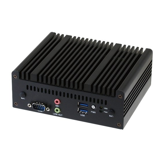
Page 11: Getting To Know Your Nano-002
Getting to know your NANO-002 The front panel includes the power button and I/O ports. Front panel WiFi WiFi LINE-OUT Back panel WiFi HDMI2 LAN2 LAN1 WiFi HDMI1 Serial port. This port is for a serial (COM) port. Line Out port (lime). This port connects a headphone or a speaker. - Page 12 Power button. This button is for switching on/off the power supply unit. HDD LED. This LED indicator flashes while reading/writing data. Power LED. This power LED lights up when you turn on the Slot-In PC. DC-In port. Plug the power adapter into this port. USB 3.0 ports. These two 9-pin Universal Serial Bus (USB) ports connect to USB 3.0/2.0 devices. • Due to USB 3.0 controller limitations, USB 3.0 devices can only be used under a Windows OS environment and after USB 3.0 driver installation. ®...
- Page 13 Chapter 2 This chapter provides step-by- step instructions on how to install components in the system.
-
Page 14: Preparation
Hold components by the edges to avoid touching the ICs on them. • Whenever you uninstall any component, place it on a grounded antistatic pad or in the bag that came with the component. Installing your NANO-002 Installing your NANO-002 Loosen the screws on the bottom cover of NANO-002 with a screwdriver. Chapter 2: Basic installation... - Page 15 Take bottom cover away from NANO-002. NANO-002N without fan NANO-002F with fan Insert the DDR4 memory to the SO-DIMM socket(s). Install the Wi-Fi module with M.2 2230 E-key connector interface and the external M.2 2280 M-Key SSD module. NANO-002...
- Page 16 Install the two metal plates. Secure the bottom cover to NANO-002 with the screws you removed earlier. NANO-002N without fan NANO-002F with fan Chapter 2: Basic installation...
- Page 17 Chapter 3 This chapter gives information about the motherboard that comes with the system. This chapter includes the motherboard layout, jumper settings, and connector locations.
-
Page 18: Motherboard Layout
Motherboard layout The NANO-002 system comes with a motherboard. This chapter provides technical information about the motherboard for future upgrades or system reconfiguration. 12.0cm(4.72in) PWR_SW2 AUDIO USB3_12 Super LED1 128Mb 2280 COM1 BIOS SPI_1 BATTERY1 2230 Intel ® M.2_TYPE_E1 Realtek 8111G Realtek 8111G M.2_TYPE_M1 CHA_FAN1 DC_PWR1 LAN1 LAN2 USB3_34... -
Page 19: Central Processing Unit (Cpu)
Central Processing Unit (CPU) This motherboard supports the 6th Generation Intel Core™ i7-6600U / i5-6300U / i3- ® 6100U Processor (FCBGA1168) Intel ® NITX-SKL1 CPU socket 6 NANO-002... -
Page 20: Installing A Dimm
Installing a DIMM This motherboard comes with two Double Data Rate 4 (DDR4) Small Outline Dual Inline Memory Module (SO-DIMM) sockets. The figure below illustrates the location of the DDR4 DIMM socket: NITX-SKL1 288-pin DDR4 DIMM sockets To install a DIMM To remove a DIMM Chapter 3: Motherboard info... -
Page 21: Jumpers
Parameter Recall (C.P.R.) feature. Shut down and reboot the system, then the BIOS automatically resets parameter settings to default values. • Due to the chipset limitation, AC power off is required before you use the C.P.R. function. You must turn off and on the power supply or unplug and plug the power cord before rebooting the system. NANO-002... -
Page 22: Connectors
Connectors Reset connector (2-pin SYSREST2) This 2-pin connector is for the chassis-mounted reset button for system reboot without turning off the system power. SYSREST2 PIN 1 NITX-SKL1 System reset connector Chassis fan connectors (4-pin CHA_FAN1) Connect the fan cables to the fan connectors on the motherboard, ensuring that the black wire of each cable matches the ground pin of the connector. - Page 23 NITX-SKL1 Power switch connector BIOS programmable connector (8-pin SPI) Use this connector to flash the BIOS ROM. SPI_1 (NC) (NC) SPI_MOSI SPI_MISO SPI_CLK SPI_CS# +V3.3SPI PIN 1 NITX-SKL1 BIOS Programmable connector M.2 socket This socket allows you to install an M.2 (NGFF) SSD module. M.2(SOCKET3) 2280 2230 M.2_TYPE_E1 M.2_TYPE_M1 NITX-SKL1 M.2(SOCKET3)s EMB-Q170B M.2(SOCKET3)s NANO-002...
- Page 24 Serial port connector (10-1 pin COM1) This connector is for serial (COM) ports. Connect the serial port module cable to this connector, then install the module to a slot opening at the back of the system chassis. COM1 PIN 1 NITX-SKL1 Com port connector NOTE: The COM module is purchased separately. Chapter 3: Motherboard info...
- Page 25 Chapter 4 This chapter tells how to change system settings through the BIOS Setup menus and describes the BIOS parameters.
-
Page 26: Bios Setup
BIOS setup program Use the BIOS Setup program to update the BIOS or configure its parameters. The BIOS screens include navigation keys and brief online help to guide you in using the BIOS Setup program. Entering BIOS Setup at startup To enter BIOS Setup at startup: • Press <Delete> during the Power-On Self Test (POST). If you do not press <Delete>, POST continues with its routines. Entering BIOS Setup after POST To enter BIOS Setup after POST: • Press <Ctrl>+<Alt>+<Del>... -
Page 27: Bios Menu Screen
For setting up BIOS security settings. Security For selecting the exit options and loading default settings. Save & Exit To select an item on the menu bar, press the right or left arrow key on the keyboard until the desired item is highlighted. NANO-002... -
Page 28: Main Menu
Main menu When you enter the BIOS Setup program, the Main menu screen appears, giving you an overview of the basic system information. Refer to section 4.1.1 BIOS menu screen for information on the menu screen items and how to navigate through them. Aptio Setup Utitlity - Copyright (C) 2017 American Megatrends, Inc. -
Page 29: Advanced Menu
SATA Configuration CPU Configuration PCH-FW Configuration Parameters USB Configuration Hardware Monitor SIO Configuration AAEON Features CSM Configuration 4.3.1 CPU Configuration The items in this menu show the CPU-related information that the BIOS automatically detects. Hyper-threading [Enabled] The Intel Hyper-Threading Technology allows a hyper-threading processor to appear as two logical processors to the operating system, allowing the operating system to schedule two threads or processes simultaneously. -
Page 30: Pch-Fw Configuration
SATA Mode Selection [AHCI] Allows you to set the working mode of the SATA controller. Configuration options: [AHCI] 4.3.3 PCH-FW Configuration Firmware Update Configuration Me FW Image Re-Flash [Disabled] This item allows you to enable or disable Me FW Image Re-Flash function. Configuration options: [Disabled] [Enabled] 4.3.4 USB Configuration The USB Devices item lists auto-detected values. If no USB device is detected, the item shows None. Legacy USB Support [Enabled] [Enabled] Enables the support for USB devices on legacy operating... - Page 31 The following items appear when Fixed Time is enabled. Wake up day/hour/minute/second [0] Specify the values for day/hour/minute/second. The following item appears when Wake System with Dynamic Time is enabled. Wake up minute increase [1] Specify the number of minutes added to the current time before waking up system. Input value range: [1~5] NANO-002...
-
Page 32: Chipset Menu
Chipset Menu The Chipset menu allows you to change the advanced chipset settings. Select an item then press <Enter> to display the submenu. Aptio Setup Utitlity - Copyright (C) 2017 American Megatrends, Inc. Main Advanced Chipset Security Boot Save & Exit PCH Parameters System Agent (SA) Configuration PCH-IO Configuration... -
Page 33: Security Menu
From the Create New Password box, key in a password, then press <Enter>. Confirm the password when prompted. To change an administrator password: Select the Administrator Password item and press <Enter>. From the Enter Current Password box, key in the current password, then press <Enter>. From the Create New Password box, key in a new password, then press <Enter>. NANO-002... - Page 34 Confirm the password when prompted. To clear the administrator password, follow the same steps as in changing an administrator password, but press <Enter> when prompted to create/confirm the password. After you clear the password, the Administrator Password item on top of the screen shows Not Installed. User Password If you have set a user password, you must enter the user password for accessing the system.
-
Page 35: Boot Menu
These items specify the boot device priority sequence from the available devices. The number of device items that appears on the screen depends on the number of devices installed in the system. • To select the boot device during system startup, press <F7> during POST. • To access Windows OS in Safe Mode, do any of the following: Press <F5> during POST. Press <F8> after POST. NANO-002 4-11... -
Page 36: Save & Exit Menu
Save & Exit menu The Save & Exit menu items allow you to load the optimal default values for the BIOS items, and save or discard your changes to the BIOS items. Aptio Setup Utility - Copyright (C)2012 American Megatrends, Inc. Main Advanced Chipset...
Need help?
Do you have a question about the NANO-002 and is the answer not in the manual?
Questions and answers