Table of Contents
Advertisement
Quick Links
Advertisement
Table of Contents

Related Manuals for Dahua SD6CE series


Summary of Contents for Dahua SD6CE series
- Page 1 IR Intelligent Speed Dome Installation Manual Version 1.0.0...
-
Page 2: Table Of Contents
Table of Contents INSTALLATION PREPARATION ................ 1 Basic Requirement ..........................1 Installation Check ..........................1 Cable Preparation ..........................1 1.3.1 The Min Specification Requirements of Cable ................1 1.3.2 Select Power Supply Cable ......................2 DEVICE INSTALLATION ..................3 Check Accessories ..........................3 Open Device ............................ - Page 3 WALL-MOUNT INSTALLATION................ 11 Installation Component and Dimension ................... 11 Wall-Mounted Installation Steps ......................11 3.2.1 Installation Conditions ........................11 3.2.2 Installation Steps ..........................12 HANG-MOUNT INSTALLATION ............... 15 Installation Component and Dimension ................... 15 Hang-mounted Bracket Installation Steps ..................15 4.2.1 Installation Conditions ........................
- Page 4 APPENDIX Ⅲ THE RELATIONSHIP BETWEEN AC 24V CABLE DIAMETER AND TRANSMISSION DISTANCE ................23 APPENDIX Ⅳ THE RELATIONSHIP BETWEEN DC 12V CABLE DIAMETER AND TRANSMISSION DISTANCE ................24 APPENDIX Ⅴ WIRE GAUGE REFERENCE SHEET ........26...
- Page 5 Welcome Thank you for purchasing our speed dome! Please read the following safeguards and warnings carefully before you install or use the product!
-
Page 6: Important Safeguards And Warnings
Important Safeguards and Warnings Safety Measures 1. Qualified Engineer Needed The installation engineer or maintenance engineer shall have corresponding CCTV system installation certificate or maintenance qualification certificate. The installation engineer or maintenance engineer shall have qualification certificate for work at height. - Page 7 All the examination and repair work should be done by the qualified service engineers. We are not liable for any problems caused by unauthorized modifications or attempted repair. Note Safety Transportation Heavy stress, violent vibration or water splash are not allowed during transportation, storage and installation.
- Page 8 Do not use gasoline, dope thinner or other chemical material to clean the shell. It may result in shell transfiguration or paint flake. Do not allow the plastic or rubber material to touch the shell for a long time. It may result in paint flake.
-
Page 9: Installation Preparation
1 Installation Preparation 1.1 Basic Requirement All installation and operation here should conform to your local electrical safety code, fire protection regulations and other relevant regulations. Make sure the application scene of the camera meets the installation requirements. Please contact dealer if you have any confusions. -
Page 10: Select Power Supply Cable
International Model Max Transmission Distance (Ft/M) 720P(25fps/30fps):1,640ft/500m SYV-75-3 720P(50fps/60fps):984ft/300m 1080P(25fps/30fps):984ft/300m Table 1-2 1.3.2 Select Power Supply Cable Refer to “Appendix 3 AC 24V Cable Diameter and Transmission Distance” for AC 24V power supply device. Refer to “Appendix 4 DC 12V Cable Diameter and Transmission Distance” for DC 12V power supply device. -
Page 11: Device Installation
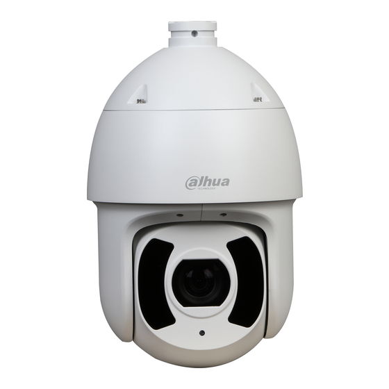
2 Device Installation 2.1 Check Accessories Before installation, please check the accessories one by one according to the packing list. Please make sure all the components listed are includes. 2.2 Open Device Please open the box and then take out the device, the device appearance is shown in Figure 2-1. Figure 2-1 Both CVI speed dome and network speed dome have the same appearance, but the internal structure differs from each other. -
Page 12: Dip Switch Setup
2.3 DIP Switch Setup 2.3.1 DIP Switch Location and Function Open the rear cover of the device, then you can see there is DIP switch on the ISP board which is above the camera module, which is shown in Figure 2-2. The DIP switch is used to set the parameters of address, baud rate and parity. -
Page 13: Baud Rate And Parity Setup
The figure of DIP switch shown in the user manual is for reference only; please refer to the actual device for more details about the DIP switch. The speed dome can use DIP switch to set address number, encoding mode can adopt binary coding. -
Page 14: Terminal Matched Resistance Setup
Figure 2-4 9(16) 10(15) Baud Rate 9600bps 4800bps 2400bps 1200bps Table 2-2 11(14) 12(13) Parity NONE EVEN NONE Table 2-3 2.3.5 Terminal Matched Resistance Setup The jumper cap which is used to set terminal resistance is located below module ISP, which is shown in Figure 2-5. - Page 15 Figure 2-5 There are two connection modes of device terminal 120Ω resistance, which has already existed on the power board. Please refer to Figure 2-6 for more details. Figure 2-6 Refer to Figure 2-11 for the default connection mode, at this moment, the jumper cap on the power board is connected to the location 2~3 of the socket and 120Ω...
-
Page 16: Reset Button Location And Micro Sd Card Slot Installation
It needs to plug out the jumper cap from 2~3 location when it needs to connect to 120Ω resistance, and then connect to the location of 1~2. In this case, 120Ω resistance is connected to the circuit, which is shown in Figure 2-8. Figure 2-8 2.4 Reset Button Location and Micro SD Card Slot Installation Open the rear cover of the speed dome, then you can see there is reset button and Micro SD... -
Page 17: Camera Cable
Make the side with metal contact of the Micro SD card face downward, (pay attention to the direction of inserting Micro SD card) insert it into the slot. Note Push the SD card according to the direction where the card is inserted, and the card will pop out automatically. -
Page 18: Cable Connection
Figure 2-11 2.5.2 Cable Connection Connect cable which is pulled out of wall to the corresponding power cable, video cable, audio cable, RS-485 control cable, alarm cable, network cable, high frequency cable and optical fiber cable etc. (according to the actual requirements) of the multi-functional combination cable, and then twine the cable connector with insulated tape to make it waterproof. -
Page 19: Wall-Mount Installation
3 Wall-Mount Installation 3.1 Installation Component and Dimension The wall-mounted bracket is shown in Figure 3-1; refer to Figure 3-2 for bracket dimension. Figure 3-1 Figure 3-2 3.2 Wall-Mounted Installation Steps 3.2.1 Installation Conditions The wall-mounted speed dome can be used on hard wall structure in both indoor and outdoor environments. -
Page 20: Installation Steps
The wall shall be thick enough to install expansion bolts. The wall shall sustain at least 8X weight of the camera and bracket etc. 3.2.2 Installation Steps Step 1 Take pedestal of wall-mounted bracket as template; confirm the location of threaded hole and screw. - Page 21 Figure 3-4 Step 4 Lift the camera and bracket to the same altitude as the punch position on the wall, use screw to fix the speed dome and bracket on the wall to complete installation, which is shown in Figure 3-5.
- Page 22 Figure 3-5...
-
Page 23: Hang-Mount Installation
4 Hang-Mount Installation 4.1 Installation Component and Dimension The hang-mounted bracket is shown in Figure 4-1; refer to Figure 4-2 for bracket dimension. Figure 4-1 Figure 4-2 Note The adjustable range of bracket length is: default 200mm, optional 400mm; it only needs to replace the connection pole. -
Page 24: Installation Steps
4.2.2 Installation Steps Step 1 As it is shown in Figure 4-3, first it needs to loosen the M4 screw on the lateral of the connection chassis to separate the connection chassis from the connection pole, and then pull the integration cable through the airproof slot at the bottom of connection chassis and make it pass through the center hole which connects to the flange and fix the connection chassis on the ceiling. - Page 25 Note It needs to twine enough Teflon tape at the top screw thread of the connection pole and then rotate the connection pole into the connection chassis firmly if the speed dome is used in the outdoor environments. Step 3 Install the quick installation connector on the connection pole, which is shown in Figure 4-5.
- Page 26 Figure 4-6...
-
Page 27: Appendix Ⅰ Lightning Proof And Surge Protection (Outdoors)
5 APPENDIX Ⅰ LIGHTNING PROOF AND SURGE PROTECTION (Outdoors) This series speed dome adopts TVS lighting protection technology. It can effectively prevent damages from various pulse signals below 6000W, such as sudden lighting and surge. While maintaining your local electrical safety code, you still need to take necessary precaution measures when installing the speed dome in the outdoor environment. - Page 28 The yellow and green GND wire or GND screw of the speed dome should be reliably connected by several strands of copper wire with no less than 25mm²and indoor equipotential GND terminal. Please refer to Figure 5-2 for lightningproof installation mode. Figure 5-2...
-
Page 29: Appendix Ⅱ About Rs485 Bus
6 APPENDIX Ⅱ ABOUT RS485 BUS 6.1 RS485 Bus Main Feature RS485 is semi duplex communication cable of impedance 120Ω. Its max load amount is 32 effective loads (including main control device and devices to be charged). 6.2 RS485 Bus Transmission Distance When we take 0.56mm (24AWG) twisted-pair as communication cable, the max transmission distance (theoretically) are listed below (according to different baud rates). -
Page 30: Rs485 Bus Faq
Figure 6-2 6.4 RS485 Bus FAQ Phenomenon Possible Reasons Solution Modify host or speed dome setup ; Speed dome Host address(baud rate) and can run self- speed dome address(baud rate) Switch RS485 positive end and diagnosis but I are not match;... -
Page 31: And Transmission Distance
7 APPENDIX Ⅲ THE RELATIONSHIP BETWEEN AC 24V CABLE DIAMETER AND TRANSMISSION DISTANCE The max transmission distance is recommended when the cable diameter is fixed and AC 24V voltage loss rate is lower than 10%. For the AC power supply devices, the max allowed voltage loss rate is 10%. -
Page 32: And Transmission Distance
8 APPENDIX Ⅳ THE RELATIONSHIP BETWEEN DC 12V CABLE DIAMETER AND TRANSMISSION DISTANCE The max transmission distance is recommended when the cable diameter is fixed and DC 12V voltage loss rate is lower than 10%. For the DC power supply devices, the max allowed voltage loss rate is 10%. - Page 33 Feet(m) 0.8000 1.000 1.250 2.000 (1.96) (3.06) (4.78) (12.25) 6.11 14.91 38.17 9.54(2.91) (1.86) (4.54) (11.63)...
-
Page 34: Appendix Ⅴ Wire Gauge Reference Sheet
9 APPENDIX Ⅴ WIRE GAUGE REFERENCE SHEET Metric bare wire Bare wire cross diameter section (mm) (mm ) 0.050 0.00196 0.060 0.00283 0.070 0.00385 0.080 0.00503 0.090 0.00636 0.100 0.00785 0.110 0.00950 0.130 0.01327 0.140 0.01539 0.160 0.02011 0.180 0.02545 0.200 0.03142 0.230...
Need help?
Do you have a question about the SD6CE series and is the answer not in the manual?
Questions and answers