
Related Manuals for 3D Systems ProJet 7000


Summary of Contents for 3D Systems ProJet 7000
- Page 1 ProJet™ 7000 3D Professional Printer Facility Requirements Guide Original Instructions Rev. C, P/N 40-D070...
-
Page 2: Table Of Contents
1.9 10.0 Contacting 3D Systems ........ -
Page 3: Projet™ 7000 Facility Requirements Guide
06.1 Air Quality and Temperature 06.2 Humidity 06.3 Lighting 06.4 Vibration and Shock 07.0 Limitations of Liability 08.0 Safety Notice 09.0 Thank You 10.0 Contacting 3D Systems 11.0 Ancillary Supplies and Equipment 12.0 Initial Site Survey Checklist 13.0 Pre-Installation Checklist... -
Page 4: What Is A Facility Requirements Guide
02.0 What is a Facility Requirements Guide This guide provides important information on selecting a facility location and planning for the installation of 3D Systems' ProJet™ 7000. It also presents planning guidelines to facilitate fast, convenient installation and operation of your modeler. -
Page 5: Symbols Used In This Guide
03.0 Symbols Used in this Guide The following table contains an illustration and description of the safety symbols which are posted on the ProJet™ 7000 and used throughout this manual. ELECTRIC SHOCK HAZARD High voltage electricity is accessible in the vicinity of this sign or behind the access panel. High voltage can cause severe burns or death. -
Page 6: The Projet™ 7000 System
04.0 The ProJet™ 7000 System Equipment Supplied by 3D Systems Material Cart Print Tray Two print platforms 3D Manage™ part preparation software Additional print platforms, print applicator mechanisms and material carts can be obtained from 3D Systems. -
Page 7: Facility Guidelines
05.0 Facility Guidelines 05.1 Moving Equipment and Access for System Installation 05.2 ProJet™ 7000 Physical Dimensions 05.3 Floor Specifications 05.4 Room Size 05.5 Electrical Requirements 05.6 Client Workstation Requirements to Operate 3DManage 05.7 Network Interface 05.8 Safety Information 05.9 Print Material Handling and Safety... -
Page 8: Moving Equipment And Access For System Installation
Weight - 100 kg (220 lbs) Note : Unpacking crates must be supervised or performed by a 3D Systems Customer Service Engineer. 3D Systems takes no responsibility for missing items if crates are opened without a Customer Service Engineer present. -
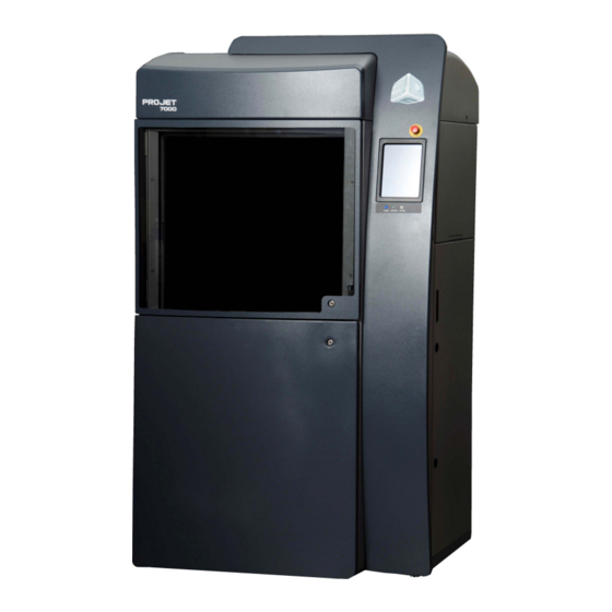
Page 9: Projet™ 7000 Physical Dimensions
05.2 ProJet™ 7000 Physical Dimensions... -
Page 12: Floor Specifications
05.3 Floor Specifications Floor Area Floors and counter spaces in the ProJet™ 7000 work area should be nonporous and suitable for cleaning with solvents. Do not install the ProJet™ 7000 on carpeted floors. The feet of the system should be on a non-resilient surface such as bare concrete. The machine should not straddle any floor seams. -
Page 13: Room Size
05.4 Room Size The total floor area required by a ProJet™ 7000 varies depending on user preferences, building codes, and the space required for storage. The room should have a minimum ceiling height of 243.84 cm, (96 in) The dashed outer lines show the space required around the system for operation, maintenance and service. -
Page 14: Electrical Requirements
05.5 Electrical Requirements Power Requirements Voltage Current Frequency Phase 100 VAC 15 amps 50/60 Hz 1 phase 115 VAC 15 amps 50/60 Hz 1 phase 230 VAC 8 amps 50/60 Hz 1 phase The system requires a dedicated, surge- and spike-protected circuit. Use of an Uninterruptible Power Supply (UPS) is strongly recommended in areas where power fluctuations are frequent, as surges and spikes can cause damage to electronic components and loss of power can result in failed builds. -
Page 15: Client Workstation Requirements To Operate 3Dmanage
Prior to installing the software, ensure that the initially selected workstation meets the following minimum specifications. The specifications described represent 3D Systems tested minimum "baseline" configuration for using the client software. It is recommended that this workstation be further enhanced for maximum performance, particularly with more powerful processors and added memory. -
Page 16: Network Interface
05.7 Network Interface Ethernet Interface The system workstation includes a Class A Ethernet interface, which can be used for connection to a Windows NT/Windows 7, part preparation workstation. This interface transmits files from the workstation to the ProJet™ 7000. The Ethernet connection is accomplished via 10/100BaseT Class A Ethernet cable with a maximum length of 182.00 m (600 ft). -
Page 17: Safety Information
05.8 Safety Information It is your responsibility to ensure that areas in which the ProJet™ 7000 and print materials are used or stored and that personnel operating the equipment comply with all relevant safety codes and laws, particularly those relating to hazardous chemicals and laser radiation. The system conforms to Federal Laser Product Performance Standards 21CFR1040.10 Class I laser in normal operation. -
Page 18: Print Material Handling And Safety
The photopolymers used in the print materials may be hazardous if handled improperly. Repeated skin contact with print materials may cause sensitization. Consult the manufacturer's Material Safety Data Sheet (MSDS) for information on specific print materials. For further information on this and related topics, consult the 3D Systems - Materials website. CAUTION Never mix different print materials. - Page 19 In-Service Life - In-Service Life of the VisiJet ProJet 7000 materials is defined as the useful life of the material after having been poured into the ProJet 7000 print tray. The In-Service Life of the Projet 7000 material greatly varies depending on material type, usage and environmental conditions.
- Page 20 Contamination - Care should be taken when cleaning windows, panels, and other parts of the ProJet™ 7000. Cleaning products which contain ammonia, should not be used because they can cause contamination of the material. Instead use a small amount of isopropyl alcohol on a paper towel to clean up spills. Accidental contamination of resins may change the material's performance characteristics to such an extent that acceptable parts can no longer be reliably created.
-
Page 21: Operating Environment
06.0 Operating Environment 06.1 Air Quality and Temperature 06.2 Humidity 06.3 Lighting 06.4 Vibration and Shock... -
Page 22: Air Quality And Temperature
06.1 Air Quality and Temperature Air Quality The room housing the ProJet™ 7000 should be well ventilated. Reasonable care should be taken to minimize dust and smoke which could contaminate the print material and cause deterioration of optical surfaces. Avoid temperature fluctuation (see below). Since dust, smoke and temperature fluctuations can affect the performance of the machine and the quality of the parts, a restricted area with positive pressure filtered air flow is recommended. -
Page 23: Humidity
06.2 Humidity Humidity The optimal humidity in the ProJet™ 7000 build chamber and lab will depend to a certain degree on the print material selection. Regardless, the humidity should always be non-condensing and should not vary outside the range of 20-50%. Review the material information (M.S.D.S./S.D.S, product datasheet, and product labeling) for specific information on recommended humidity levels. -
Page 24: Lighting
06.3 Lighting Standard fluorescent lamps with clear plastic diffusers are recommended to minimize ultraviolet exposure, which could negatively affect the print material. UV filters are available for windows and exposed fluorescent lamps. Make certain to avoid the following: Sunlight, quartz-halogen lamps, and high-intensity incandescent lamps are not suitable. UV-intensive lighting or ultraviolet exposure through windows should be avoided. -
Page 25: Vibration And Shock
06.4 Vibration and Shock Floor Vibration and Shock The system is a precision mechanical and optical machine that is sensitive to vibration. In order to ensure part quality and accuracy, a ground floor location with a concrete floor, (miminum of 4 inches thick) is recommended. The ProJet™... -
Page 26: Limitations Of Liability
3D Systems is not, in any event, liable for any damages, including lost profits, cost of cover, or other special, incidental, consequential, or indirect damages arising from the use of this document, however caused and on any theory of liability. This limitation will apply even if 3D Systems or an authorized dealer or representative has been otherwise advised of the possibility of such damage. -
Page 27: Safety Notice
All service to the laser process machine, the embedded laser system and optics requiring interlock override shall only be performed by 3D Systems Corporation service personnel, their authorized agents, or personnel trained by 3D Systems Corporation. The manufacturer's user information for the incorporated laser products are supplied with this process machine. -
Page 28: Thank You
09.0 Thank You 3D Systems is confident that you will be very satisfied with the purchase of your ProJet™ 7000. Enjoy the ability to produce high quality models from your 3-D digital data. We are dedicated to developing a relationship that extends beyond the terms of the sale. Please take the time to contact 3D Systems with questions, comments or suggestions about your ProJet™... -
Page 29: Contacting 3D Systems
10.0 Contacting 3D Systems U.S.A. 3D Systems, Inc. 333 Three D Systems Circle Rock Hill, SC 29730 U.S.A. General Inquiries: (803) 326-3900 Material Orders: (800) 889-2964 Customer Support: (800) 793-3669 E-mail: moreinfo@3dsystems.com Germany 3D Systems GmbH Guerickeweg 9 D-64291 Darmstadt,... -
Page 31: Ancillary Supplies And Equipment
Tel: 201-327-9100 Miscellaneous Supplies (available from many lab safety companies): • Cellulose Wadding (drain pads) • Chemically Resistant Gloves (3D Systems recommends surgical-type 100% nitrile gloves) • Eye Wash Stations • Fire Extinguisher • Fire Proof Waste Can • Fire-resistant Storage Cabinets •... -
Page 32: Initial Site Survey Checklist
12.0 Initial Site Survey Checklist Initial Site Survey Checklist will help you determine the optimal place to install the ProJet™ 7000. Survey your facility and list three possible installation locations at the top of the form. Review all questions on the form and check the box for the location that satisfies the requirements presented by that particular question. Total the number of checked boxes for each location. -
Page 33: Pre-Installation Checklist
13.0 Pre-Installation Checklist The Pre-Installation Checklist helps you prepare for installing the ProJet™ 7000. Prior to installation, complete the checklist and fax it to your 3D Systems Customer Support Engineer. -
Page 34: Pre-Installation Checklist
Is a cabinet available to store print material containers? (Workstations and Network access) Does the room have a door that can be closed and Has 3D Systems software been loaded on at least locked during installation? one workstation so that we can submit a build job...
Need help?
Do you have a question about the ProJet 7000 and is the answer not in the manual?
Questions and answers