
Related Manuals for Snorkel UL40


Summary of Contents for Snorkel UL40
- Page 1 PARTS & SERVICE MANUAL Ansi Part Number: 511128- MAY 2013 Serial Number 21691 - 060000...
-
Page 3: Manual Force
ULII - 25/32/40 Portable Personnel Lifts When contacting Snorkel for service or parts information, be sure to include the MODEL and SERIAL NUMBERS from the equipment nameplate. Should the nameplate be missing, the SERIAL NUMBER is also stamped on the chassis tube on the right side of the mast. -
Page 4: Table Of Contents
Contents Table of Contents List of Illustrations Section Page Number Figure Page 1.0 Introduction ............. 1-1 Number UL Portable Personnel Lifts ........1-1 Purpose of Equipment ........1-1 General Description ..........1-1 Lubrication ..............2-3 Platform ............1-1 Hydraulic Power Unit ..........2-3 Mast .............. -
Page 5: Introduction
UL-25/32/40 SEVICE AND PARTS MANUAL OREWORD OW TO ANUAL This manual is divided into six sections. NTRODUCTION ECTION General description and machine specifications. PERATION AND PECIFICATIONS ECTION Information on how to operate the work platform and how to prepare it for operation. AINTENANCE ECTION Preventative maintenance and service information. - Page 6 Please understand that these warnings cannot cover all conceivable ways in which service, whether or not recommended by Snorkel, might be done, or of the possible hazardous consequences of each conceivable way, nor could Snorkel investigate all such ways.
- Page 7 Introduction & Specifications Section 1.1 I NTRODUCTION URPOSE The purpose of this service and parts manual is to provide instructions and illustrations for the operation and maintenance of the . l e UL25/32/40 This manual must be stored on the machine at all times. Read, understand and follow all safety rules and operating instructions before attempting to operate the machine.
- Page 8 NEVER charge batteries near sparks or open flame. Charging batteries emit explosive hydrogen gas. Modifications to the aerial work platform are prohibited or permissible only at the approval by Snorkel. AFTER USE, secure the work platform from unauthorized use by turning keyswitches off and removing key.
-
Page 9: General Description
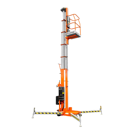
Introduction ................3 General Description . - Page 10 Introduction Figure 1-1: UL Portable Personnel Lift Work Platform 1. Platform 9. Battery Box (DC Units) • Battery 2. Mast • Battery Charger 3. Chassis 10. Casters 4. Outriggers 11. Rear Wheels 5. Guardrail 12. Screw Jacks 6. Entry Drop Bar 13.
- Page 11 DO NOT attempt to move this machine with the mast in an elevated position This machine weighs in excess of 760lb (345kg) and MUST only be manoeuvred on firm, level ground...
-
Page 12: Controls And Indicators
Controls and Indicators Controls and Indicators Platform Controls Chassis Controls 1 Power Indicator 4. Emergency Lowering Valve 2. Emergency Stop 5. Orbit Level Switch 6. Outrigger Indicator 3. Key Switch Lights 1 Emergency Stop Switch 2. Power On Button 3. Up Button 4. -
Page 13: Outrigger Installation
Outrigger Installation Installing Outriggers 1. Remove the outriggers from storage Indicator Lights Bubble Level locations on the sides of the mast. 2. Insert into the outrigger socket in the base (Figure 1). Locking Pin 3. Push in until the locking pin engages the hole in the end of the outrigger. -
Page 14: Safety Interlock Test
Pre-Operation Safety Inspection Hydraulic Reservoir NOTE: Carefully read, understand and follow all safety rules, operating instructions, labels and National Safety Instructions/Requirements. Perform the following steps each day before use. 1. Check that all four (4) outriggers are properly installed. 2. Check that the base is level. 3. -
Page 15: Platform
Operation Before operating the machine, ensure that the Pre-Operation Safety Inspection has been completed and that any deficiencies have been corrected. Never operate a damaged or malfunctioning machine. The operator must be thoroughly trained on this machine. 1. AC Units: connect the power unit plug to an approved extension cord. 2. -
Page 16: Transporting The Work Platform
9. Secure the unit with suitable tie straps using the forklift pockets located under the base of the unit, and either the upper caster axle on the UL25 models or the tilt back frame on the UL32 and UL40 models. -
Page 17: Dc Models
Transporting the Work Platform 1. Unsecure the unit. 2. Release the locking pin and pull the T-handle out until the locking pin engages the hole in the end of the T-handle. 3. Roll the unit back until the rear wheels are off the edge of the tailgate or vehicle bed. 4. -
Page 18: Passage Through A Doorway
Passage Through a Doorway The UL32 and UL40 are equipped with a castered rear Tilt Back assembly. When the unit is tilted back onto this support frame, the overall height is reduced to allow the unit to pass through a standard doorway. - Page 19 Passage Through a Doorway Passing Through Doorways Retaining Pin Tilt Back Handle Hair Pin Retainer Retaining Pin Cylinder Assembly Lowering and Raising with the Tilt Back Handle Cylinder Secured with Retaining Pin Compressing the Cylinder Assembly Page 12 Operation Manual...
- Page 20 Always wear safety glasses when working near batteries. Battery fluid is highly corrosive. Thoroughly rinse away any spilled fluid with clean water. Always replace batteries with Snorkel batteries or manufacturer approved replacements weighing 22 kg (48 lbs.) each. • Check the battery fluid level daily, especially if the work platform is being used in a warm, dry climate.
- Page 21 The Complete Inspection consists of periodic visual and operational checks, along with periodic minor adjustments that assure proper performance. Daily inspection will prevent abnormal wear and prolong the life of all systems. The inspection and maintenance schedule should be performed at the specified inter- vals.
- Page 22 Daily Preventative Maintenance Checklist OTES Operation Manual Page 15...
- Page 23 Labels These labels shall be present and in good condition before operating the work platform. Be sure to read, understand and follow these labels when operating the work platform. Page 16 Operation Manual...
- Page 24 Specifications 390Kg (860lbs) 470Kg (1040lbs) 435Kg (960lbs) 2.06m (81 in) 2.06m (81 in) 2.95m (116 in) 1.98m (78 in) 2.84m (112 in) 2.53m (100 in) 2.90m (114 in) 1.32m (52in) 1.32m (52 in) 1.94m (76 in) 1.94m (76 in) 3.05m (120 in) Toeboard 152mm (6 in) High Max Chassis Inclination...
-
Page 25: Table Of Contents
This section contains instructions for the maintenance of the Work Platform. Refer to the General Informa- tion section for information relevant to all Snorkel work platforms. Referring to the Operator Manual will aid in understanding the operation and function of the various components and systems of the work platform, and help in diagnosing and repair of the machine. -
Page 26: Mast
Section Maintenance 2.5 Mast Assembly - Disassembly ...................... 2-6 Pla orm Assembly Removal ......................2-6 #6 Mast Disassembly ........................2-6 #5 Mast Disassembly ........................2-6 #3 Mast Disassembly ........................2-9 #2 Mast Disassembly ........................2-9 #2 Mast Assembly ..........................2-9 #3 Mast Assembly .......................... - Page 27 Section Maintenance 4.1 Electrical Schematics ........................4-2 Electrical Schematic Legend AC ....................... 4-2 Electrical Schematic Legend DC ....................... 4-2 4.2 Hydraulic Schematics ........................4-4 Hydraulic Schematic Legend ......................4-4 5.0 Illustrated Parts Breakdown ......................5-1 Table of Contents ..........................5-1 UL-25/32/40 Portable Personnel Lifts...
-
Page 28: 2.0 Introduction
Section Maintenance 2.0 Introduction 2.1 Preventative Maintenance (Table 2-1) This section contains instructions for the maintenance of the UL-Series Lifts. Procedures for the operational check- The complete inspection consists of periodic visual and out adjustment, scheduled maintenance, and repair/ operational checks, together with all necessary adjustments removal are included. -
Page 29: Preventative Maintenance Table Key
Section Maintenance Table 2-1: Preventative Maintenance Preventative Maintenance Table Key Interval COMPONENT INSPECTION OR SERVICES INTERVAL Battery Check electrolyte level Daily Daily=each shift or every day System Check battery cable condition Daily 30d=every month or 30 days (DC Units Charge batteries Daily 3m=every 3 months only) -
Page 30: 2.2 Lubrication
Section Maintenance 2.2 Lubrication Refer to Figure 2-1 for location of items that require lubrication service. Use an aerosol chain lubricant for all components to be lubricated that require oil. CASTERS Using a grease gun, apply 1 or 2 shots of multi-purpose bearing grease to each zerk fitting. -
Page 31: Battery Maintenance (Dc Units Only)
Section Maintenance 2.3 Battery Maintenance BATTERY CHARGING (Figure 2-3) Charge battery at end of each work shift or sooner if (DC units only) battery has been discharged. Electrical energy for the motor is supplied by a 12-volt battery. Proper care and maintenance of the battery and motor will ensure maximum performance from the lift. -
Page 32: Battery Cell Equalization
Section Maintenance BATTERY CELL EQUALIZATION The specific gravity of the electrolyte in the battery cells should be equalized monthly. To do this, charge batteries as outlined in Battery Charging. After this initial charge, Check the hydraulic system pressure whenever the check the electrolyte level in all cells and add distilled pump or relief valve has been serviced or replaced. -
Page 33: Mast Assembly (Figure 2-6,2-7) Disassembly
Section Maintenance 3. Remove cotter pins, and drive out chain retaining pins 2.5 Mast Assembly (Figure 2-6,2-7) from the top front of stage 5. Disassembly 4. Loosen screws from strap retainer on stage 5 top casting. Pull strap free of retainer. Using a suitable lifting device, lower the work platform 5. - Page 34 Section Maintenance Figure 2-6: Mast Assembly, Strap and Chain Detail UL-25/32/40 Portable Personnel Lifts...
- Page 35 Section Maintenance Figure 2-7: Mast Assembly, Bearing Detail UL-25/32/40 Portable Personnel Lifts...
-
Page 36: Mast
Section Maintenance 2.5 Mast Assembly (Cont.) #4 Mast 1. Set #4 mast in place with the sequencing strap inside 4. Disconnect chain from top of #2 mast. and the chains on the bottom. 5. Remove cylinder by following instructions in Section 2.7. 2. -
Page 37: Mast
Section Maintenance 2.5 Mast Assembly (Cont.) 2.6 Cylinder Assembly SEAL REPLACEMENT (Figure 2-8) Platform Support Assembly Note: The Lift Cylinder Seal can be accessed from the 1. Slide cage support weldment into the top of the bottom of the Lift without removing the Cylinder platform assembly weldment. - Page 38 Section Maintenance 7. Remove the seal retainer, using the spanner wrench, 14. Rod and rod end threads must be absoloutly clean. ® 062521-010. Spray threads with Loctite primer #7471, allow to dry for five minutes. Coat threads liberally with 8. Clean all sealing surfaces with solvent. Inspect ®...
-
Page 39: Cylinder Assembly (Cont.)
Section Maintenance 8. Clean orifice valve hole with a straight pin. Flush with 2.6 Cylinder Assembly (Cont.) solvent to remove any contamination that may remain in bleeder tube. ORIFICE VALVE CLEANING 9. Reinstall orifice / bleeder tube into rod end cap and Using a suitable lifting device, lower the work platform secure with snap ring. -
Page 40: Cylinder Removal (Figure 2-9)
Section Maintenance 7. Remove the screws and washers, attaching the #2 and #3 bottom castings to the #2 and #3 mast assemblies. 8. While keeping tension on the tie rods, slide the cylinder and #2 and #3 bottom castings out the bottom of the UL Lift far enough to expose both castings. -
Page 41: Cylinder Assembly (Cont.)
Never operate a machine with the pinch shield removed, except for inspection. FASTENERS Use the following values to torque fasteners used on Snorkel Work Platforms unless a specific torque value is called out for the part being installed. Table 2-3: Bolt Torque... -
Page 42: General Procedure
Table 3-1 provides a logical sequence of tests that are thoroughly study both hydraulic and electric schematics to designed to isolate problems with the Snorkel Lift. This determine possible causes. Loose terminal connections and table includes a list of probable causes and remedies. -
Page 43: Battery Charger
Troubleshooting Table 3-1: Troubleshooting TROUBLE PROBABLE CAUSE REMEDY TROUBLE PROBABLE CAUSE REMEDY Lift Function 1. Extension cord too Use minimum 1,5 mm (12 ga.) cord of Test for continuity across Solenoid. Platform does 1. Down Valve Solenoid inoperable, long or insufficient 16m (50 feet) or less in length. - Page 44 Troubleshooting Table 3-1: Troubleshooting (cont'd) LIFT DOES NOT TURN ON - AC 2) Pull out both E-Stop switches. Activate the common and up switch on the All voltages arereferenced to Chassis ground. Using avoltmeter, placethe negative probe upper control box. directly to a clean ground source onthe AC motor.If equipped with battery back up, 2a) Motor does not run.
-
Page 45: Circuit Board
Troubleshooting Table 3-1: Troubleshooting (cont'd) LIFT DOES NOT RAISE - DC 2) Check circuit board for correct output. Open the lid on the lower control box. Using a voltmeter, check the voltage terminal S27 found on the upper right hand side of the circuit board. - Page 46 Troubleshooting Table 3-1: Troubleshooting (cont'd) LIFT DOES NOT LOWER - DC 1) Lift will raise but will not lower. Turn on key switch, pull out both upper and lower E-Stops. Press the common and down push buttons on the upper control box.
- Page 47 Troubleshooting NOTES UL-25/32/40 Portable Personnel Lifts...
- Page 48 Schematics 4.0 Introduction LIST OF FIGURES This section contains electrical and hydraulic power sche- Figure Page matics and associated information for maintenance purposes. Figure 4-1: Electrical Schematic, AC Models ....4-3 Figure 4-2: Electrical Schematic, DC Models ....4-3 The diagrams are to be used in conjunction with Table 3-1: Figure 4-3: Hydraulic Schematic ........
-
Page 49: Electrical Schematics
Schematics 4.1 Electrical Schematics Table 4-1: Electrical Schematic Legend AC Table 4-2: Electrical Schematic Legend DC REFERENCE REFERENCE DESIGNATION NAME FUNCTION LOCATION DESIGNATION NAME FUNCTION LOCATION Bridge Rectifier Converts AC to DC In Control Box. Battery Supplies current to In Power Module. for control circuit. -
Page 50: Electrical Schematic, Ac Models
Schematics SOL1 SOL2 S3 S4 Figure 4-1: Electrical Schematic, AC Models Figure 4-2: Electrical Schematic, DC Models UL-25/32/40 Portable Personnel Lifts... -
Page 51: Hydraulic Schematic
Schematics 4.2 Hydraulic Schematic Table 4-3: Hydraulic Scematic Legend REFERENCE DESIGNATION NAME FUNCTION LOCATION Valve, Check Allows flow in one Valve Block Assembly direction. Cylinder Operates Lift On lift assembly. Filter Seperates matter Inline with Pump. held in suspension from fluid. Orifice Controls flow out Inline with CYL. - Page 52 Tilt Back Assembly, UL32 UL40 068006-026 ......5-4 068200-000 ........5-32...
-
Page 53: Final Assembly, Ulii Series
Final Assembly, ULII Series UL25 068001-002, 068001-003, UL32 068002-002, 068002-003, UL40 068003-002, 068003-003 BASIC ASSY 068006-024 BASIC ASSY 068006-025 BASIC ASSY 068006-026 POWER OPTION AC EUR. 068008-011 068009-011 POWER OPTION DC EUR. 068013-012 LABEL KIT/INST. LABEL KIT/INST. 068013-013 068014-012 LABEL KIT/INST. - Page 54 ULII Series Parts Manual...
-
Page 55: Basic Assembly
Basic Assembly UL25 068006-024 UL32 068006-025 UL40 068006-026 512805-000 512789-000 512806-000 ULII Series Parts Manual... - Page 56 Drawing # 1 of 2 ULII Series Parts Manual...
- Page 57 Drawing # 2 of 2 ULII Series Parts Manual...
-
Page 58: Ac Power Option
AC Power Option 068008-011 020809-001 FITTING, TEE 6MJ-6MB-6FJX ULII Series Parts Manual... - Page 59 ULII Series Parts Manual...
-
Page 60: Dc Power Option 068009-011
DC Power Option 068009-011 ULII Series Parts Manual... - Page 61 5-10 ULII Series Parts Manual...
-
Page 62: Ac Control Box
AC Control Box 068007-021 ULII Series Parts Manual 5-11... - Page 63 5-12 ULII Series Parts Manual...
-
Page 64: Dc Control Box
DC Control Box 068007-023 ULII Series Parts Manual 5-13... - Page 65 ULII Series Parts Manual Page 15...
-
Page 66: Lift Cylinder
Lift Cylinder UL25 068074-020 UL32 068074-021 UL40 068074-022 Page 16 ULII Series Parts Manual... - Page 67 ULII Series Parts Manual Page 17...
-
Page 68: 2Nd Stage Mast Assembly
2nd Stage Mast Assembly UL25 068050-001 UL32 068050-002 UL40 068050-003 Page 18 ULII Series Parts Manual... -
Page 69: 3Rd Stage Mast Assembly
3rd Stage Mast Assembly UL25 068056-001 UL32 068056-002 UL40 068056-003 ULII Series Parts Manual Page 19... -
Page 70: 4Th Stage Mast Assembly
4th Stage Mast Assembly UL25 068061-001 UL32 068061-002 UL40 068061-003 Page 20 ULII Series Parts Manual... -
Page 71: 5Th Stage Mast Assembly
5th Stage Mast Assembly UL25 068066-001 UL32 068066-002 UL40 068066-003 ULII Series Parts Manual Page 21... -
Page 72: 6Th Stage Mast Assembly
6th Stage Mast Assembly UL25 068070-001 UL32 068070-002 UL40 068070-003 Page 22 ULII Series Parts Manual... - Page 73 OTES ULII Series Parts Manual Page 23...
-
Page 74: Cage Support Assembly
Cage Support Assembly UL25 068160-009 UL32 068160-010 UL40 068160-011 Page 24 ULII Series Parts Manual... - Page 75 ULII Series Parts Manual Page 25...
-
Page 76: Platform Assembly, Ul25
Platform Assembly, UL25 068179-003 506275-001 057524-001 DROP BAR ASSY 510524-000 510542-000 PUSH BUTTON ENABLE 0120804 PUSH BUTTON DOWN 0120803 PUSH BUTTON UP Page 26 ULII Series Parts Manual... - Page 77 ULII Series Parts Manual Page 27...
-
Page 78: Platform Assembly, Ul32/Ul40
Platform Assembly, UL32/UL40 068179-004 506275-001 057524-001 DROP BAR ASSY 026551-007 RIVET 1/8 .251 - .312 GRIP Page 28 ULII Series Parts Manual... - Page 79 ULII Series Parts Manual Page 29...
-
Page 80: Loader Assembly, Ul25
Loader Assembly, UL25 068194-000 Page 30 ULII Series Parts Manual... - Page 81 OTES ULII Series Parts Manual Page 31...
-
Page 82: Tilt Back Assembly, Ul32
Tilt Back Assembly, UL32 068200-000 Page 32 ULII Series Parts Manual... - Page 83 ULII Series Parts Manual Page 33...
-
Page 84: Tilt Back Assembly, Ul40
Tilt Back Assembly, UL40 068200-001 Page 34 ULII Series Parts Manual... - Page 85 ULII Series Parts Manual Page 35...
-
Page 86: Loader Stop Bracket Assembly
Loader Stop Bracket Assembly 068190-000 Drawing # Page 36 ULII Series Parts Manual... -
Page 87: Loader Bar Assembly
Loader Bar Assembly 068186-000 ULII Series Parts Manual Page 37... -
Page 88: Outrigger Assembly
Outrigger Assembly UL25 068157-000 UL32 068157-001 UL40 068157-002 Page 38 ULII Series Parts Manual... - Page 89 ULII Series Parts Manual Page 39...
- Page 90 Power Pack Option 068100-001 ULII Series Parts Manual Page 40...
- Page 91 Electrical Schematic, AC 068010-000 Page 41 ULII Series Parts Manual...
- Page 92 Electrical Schematic, DC 068010-001 ULII Series Parts Manual Page 42...
-
Page 93: Hydraulic Schematic
Hydraulic Schematic 068011-002 Page 43 ULII Series Parts Manual... - Page 94 Local Distributor / Lokaler Vertiebshändler / Distributeur local El Distribuidor local / ll Distributore locale EUROPE, MIDDLE EAST AFRICA & ASIA PHONE: +44 (0) 845 1550 057 FAX: +44 (0) 845 1557 756 NORTH & SOUTH AMERICA PHONE: +1 785 989 3000 TOLL FREE: +1 800 225 0317 FAX: +1 785 989 3070 AUSTRALIA...
Need help?
Do you have a question about the UL40 and is the answer not in the manual?
Questions and answers