Table of Contents
Advertisement
Quick Links
*911395-00*
911395-00
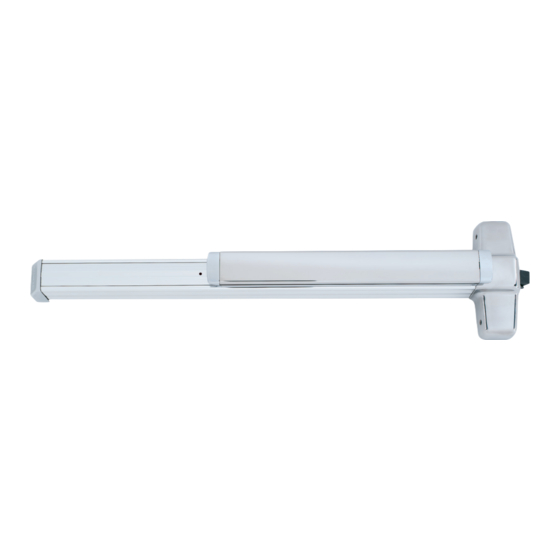
Rim Exit Device
BS EN 1125 : 2008
Please give these instructions to building owner after device is installed
#10-24 tap
#25 drill bit (approximately. 4 mm dia.)
10 mm dia. drill bit (for sex bolts)
13 mm dia. drill bit
16 mm dia. spade drill (for #825 sex bolts)
Hacksaw
Sabre saw
This product is covered by the
following patent numbers:
3,767,238
3,854,763
4,167,280
98/99, 98/99-F,
& CD98/CD99
Devices covered by these Instructions:
98/99-F (Fire) Rim Exit Device
CD98/CD99 (Cylinder Dogging) Rim Exit Device
Special Tools Required:
4,427,223
4,466,643
4,741,563
1-877-671-7011
98/99 Rim Exit Device
• Screw chart .............................
• General Information .................
• Device installation ...............
• Preparation chart .....................
• 1609 strike installation ............
• Cut device ...............................
• 499F strike installation ...........
Customer Service
www.allegion.com/us
Installation Instructions
Index:
2
3
4-5
6
7
8
8
© Allegion 2015
Printed in U.S.A.
911395-00 Rev. 10/15-e
Advertisement
Table of Contents

Related Manuals for Allegion Von Duprin 98/99


Summary of Contents for Allegion Von Duprin 98/99
- Page 1 • Cut device ....... Hacksaw • 499F strike installation ... Sabre saw This product is covered by the following patent numbers: 3,767,238 4,427,223 3,854,763 4,466,643 4,167,280 4,741,563 © Allegion 2015 Customer Service Printed in U.S.A. 911395-00 Rev. 10/15-e 1-877-671-7011 www.allegion.com/us...
-
Page 2: Screw Chart
SCREW CHART Metal frame #10-24 X 19mm Wood frame #10 X 38mm Wood screw Metal frame #10-24 X 19mm Wood frame #10 X 38mm Wood screw Surface mount or #10-24 X 25mm Sex bolts ( 45mm door) Sex bolts ( 57mm door) #10-24 X 38mm Surface mount (wood) #10 X 32mm Wood screw... -
Page 3: General Information
GENERAL INFORMATION These exit devices can be installed on the door widths listed below: Device Size Code/Standard Requirement Effective Door Width Device & Strike 98/99Rim(299) 813 mm BS EN 1125 : 2008 662 mm - 762 mm 98/99Rim(299) 1118 mm BS EN 1125 : 2008 814 mm - 1016 mm EL98/99Rim(299) - Page 4 Draw Horizontal Device and Strike Center Line ( Position Template Against Strike and on then Mark Door Template (align on against strike) RHR Shown (LHR opposite) 1011mm To finished For double doors with a floor mullion and strike already Mark 6 installed, use existing holes strike center line.
- Page 5 Install 2 Support Screws and Center Case Cover Install Tailpiece Guide Remove protective film from pushbar Tailpiece guide Center Tailpiece case Cut tailpiece cover if needed 13mm Rotate tailpiece guide to match tailpiece Support screws (2) Install Trim (if using) and Secure Device Center Case For 98F/99F (fire rated) devices on to Door wood or composite door:...
-
Page 6: Preparation Chart
PREPARATION CHART Go to instructions on next page before using preparation chart *End cap bracket - 2 holes Center case - 4 holes Surface mount Sex bolts Surface mount Sex bolts or 990 trims #25 Drill 6mm Drill (device side) #25 Drill 6mm Drill (device side) #10-24 tap... - Page 7 PREPARATION FOR 1609 STRIKE 95 mm 111 mm NOTE minimum stile minimum stile A coordinator must be used on inactive door. If used, astragal must be attached to active door Vertical rod device shown inactive 1609 strike Rim device shown active of opening 1609 strike 19 mm...
-
Page 8: Cut Device
CUT DEVICE Measure amount to cut off device. Cut device square. 38mm minimum clearance (with endcap removed) Cut device square NOTE: Device must and remove all be cut square for Device aligned burrs with mounting proper end cap fit holes Note If 16mm diameter wire access hole has been predrilled in door,... -
Page 9: Additional Installation Requirements
ADDITIONAL INSTALLATION REQUIREMENTS • Before installation ensure door and frame are in good condition, correctly hung and not distorted Note - Maximum door distortion of 5mm to ensure safe exit. • It is not recommended that exit devices be fitted to hollow core doors unless specially designed for this type of door. -
Page 10: Maintenance Instructions
MAINTENANCE INSTRUCTIONS To ensure performance in accordance with the relevant standard, the following routine maintenance checks should be undertaken at intervals of not more than one month. Inspect and operate the emergency exit device to ensure that all components are in a satisfactory working condition. - Page 11 52mm and including sub facings comprising a minimum of 3mm thick non- combustible board, with their lock cylinders wrapped with a 1mm thick Interdens intumescent. For additional information and full details of certification and fire door suitability: Telephone : 01922 707400 www.allegion.com...
Need help?
Do you have a question about the Von Duprin 98/99 and is the answer not in the manual?
Questions and answers