Table of Contents
Advertisement
Advertisement
Table of Contents

Subscribe to Our Youtube Channel
Related Manuals for SRAM GUIDE RSC 2015


Summary of Contents for SRAM GUIDE RSC 2015
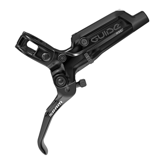
- Page 1 2015 GUIDE RSC Service Manual...
- Page 2 LIMITATIONS OF LIABILITY To the extent allowed by local law, except for the obligations specifically set forth in this warranty statement, in no event shall SRAM or its third party suppliers be liable for direct, indirect, special, incidental, or consequential damages.
-
Page 3: Table Of Contents
TABLE OF CONTENTS BRAKE SERVICE OVERVIEW................................5 LEVER SERVICE ....................................6 PARTS AND TOOLS NEEDED FOR SERVICE ................................... 6 GUIDE RSC EXPLODED VIEW ........................................6 LEVER BLADE REMOVAL ..........................................7 PISTON ASSEMBLY REMOVAL ........................................10 PISTON ASSEMBLY INSTALLATION ......................................13 LEVER BLADE INSTALLATION ........................................17 CALIPER SERVICE ...................................20 PARTS AND TOOLS NEEDED FOR SERVICE ..................................20 CALIPER EXPLODED VIEW ...........................................20... - Page 4 SAFETY FIRST! We care about YOU. Please, always wear your safety glasses and protective gloves when servicing SRAM products. Protect yourself! Wear your safety gear!
-
Page 5: Brake Service Overview
B r a k e S e r v i c e O v e r v i e w SRAM brake systems need to be serviced periodically to optimize braking function. If brake fluid is leaking from any area of the brake, there may be damage or wear and tear to the internal moving parts. -
Page 6: Lever Service
• 2 mm & 4 mm hex wrench • Avid High-Performance 5.1 DOT Fluid or DOT 4 Fluid, or Avid • Torque wrench DOT Grease • SRAM® Guide Lever Internals Assembly Tool • Needle nose pliers (for setting pushrod distance and installing internals) • 242® Blue Loctite®... -
Page 7: Lever Blade Removal
L e v e r B l a d e R e m o v a l N O T I C E DOT fluid will damage painted surfaces. If any fluid comes in contact with a painted surface (i.e. your frame) or printing on the brakes, wipe it off immediately and clean it with isopropyl alcohol or water. - Page 8 Use a T10 TORX® wrench to remove the reservoir cap bolt nearest to the lever blade. T10 TORX wrench Carefully turn the lever body upside down so that the detent spring and ball fall out of the lever body. If they do not initially fall out, gently tap the lever against a clean rag.
- Page 9 Pour the fluid from the brake lever body into a pan. Separate the bladder from the reservoir cover. Spray isopropyl alcohol on the bladder and the reservoir cover and clean them with a rag. N O T I C E All components must be completely dry before reinstalling them.
-
Page 10: Piston Assembly Removal
P i s t o n A s s e m b l y R e m o v a l Use a T8 TORX® wrench to remove the SwingLink™ pinch bolt. T8 TORX wrench Use a T8 TORX® wrench to push the SwingLink pivot pin out of the lever body. - Page 11 Remove the SwingLink™ bushings by hand. Use a SRAM Guide Lever Internals Assembly Tool to unthread the piston sleeve and coupler. Insert the SRAM Guide Lever Internals Assembly Tool into the lever body and align the keyslot of the tool with the piston sleeve.
- Page 12 Place a rag over the lever body to prevent the piston assembly spring from forcefully ejecting across the room. Use your hand to push out the contact knob. C A U T I O N - E Y E H A Z A R D Use safety glasses.
-
Page 13: Piston Assembly Installation
Spray isopropyl alcohol on the lever body and both of your gloves and clean with a rag. Use the SRAM Guide Lever Internals Assembly Tool to press the piston into the lever body while inserting the contact adjust knob into the contact adjust slot. - Page 14 Use your hand to place the sleeve on the coupler. The sleeve threads must be oriented away from the base of the coupler. Use the SRAM Guide Lever Internals Assembly Tool tool to engage T8 TORX wrench and thread the sleeve and coupler onto the piston assembly.
- Page 15 SwingLink. SRAM Guide Lever Internals Assembly Tool 2 mm hex wrench Use a 2 mm hex wrench to remove the SwingLink from the SRAM Guide Lever Internals Assembly Tool and place the pushrod into the coupler sleeve. SRAM Guide Lever Internals Assembly Tool...
- Page 16 Align the holes of the SwingLink™ and the SwingLink bushings, then press the pivot pin into the hole until it is flush with the lever body. Apply a small amount of 242® Blue Loctite® onto the pinch bolt. T8 TORX wrench Use a T8 TORX®...
-
Page 17: Lever Blade Installation
L e v e r B l a d e I n s t a l l a t i o n Use your hand to install the lever blade. Line up the pivot holes of the lever blade with the pivot holes in the lever body. - Page 18 Use a torque wrench and a T10 TORX® bit socket to tighten each pivot bolt to 2.7-3.2 N·m (24-28 in-lb). T10 TORX bit 2.7-3.2 N•m (24-28 in-lb) 22 mm Press the bladder into the reservoir cap, make sure the bladder is properly seated into the reservoir cap.
- Page 19 Use a torque wrench and a T10 TORX® bit socket to tighten each reservoir cap bolt to 2.7-3.2 N·m (24-28 in-lb). T10 TORX bit 2.7-3.2 N•m (24-28 in-lb) 22 mm Spray isopropyl alcohol on the lever body and clean it with a rag.
-
Page 20: Caliper Service
C a l i p e r S e r v i c e P a r t s a n d T o o l s N e e d e d f o r S e r v i c e •... -
Page 21: Troubleshooting
T r o u b l e s h o o t i n g 'Sticky' or slow brake pad return feel/excessive lever throw If your brakes feel sticky, and exhibit slow brake pad return and/or excessive brake lever throw, it may be a result of the pistons sticking in the caliper. -
Page 22: Caliper Brake Pad Removal
C a l i p e r B r a k e P a d R e m o v a l N O T I C E DOT fluid will damage painted surfaces. If any fluid comes in contact with a painted surface (i.e. your frame) or printing on the brakes, wipe it off immediately and clean it with isopropyl alcohol or water. -
Page 23: Caliper Piston Removal
C a l i p e r P i s t o n R e m o v a l N O T I C E DOT fluid will damage painted surfaces. If any fluid comes in contact with a painted surface (i.e. your frame) or printing on the brakes, wipe it off immediately and clean it with isopropyl alcohol or water. - Page 24 Remove the internal caliper o-ring from the outboard caliper half. Place one of the caliper halves, piston side down, on a soft rubber mat or a small section of inner tube on a flat surface. Insert a rubber-tipped blow gun chuck nozzle into the banjo port. C A U T I O N - E Y E H A Z A R D Wear safety goggles.
-
Page 25: Caliper Piston Installation
C a l i p e r P i s t o n I n s t a l l a t i o n N O T I C E DOT fluid will damage painted surfaces. If any fluid comes in contact with a painted surface (i.e. your frame) or printing on the brakes, wipe it off immediately and clean it with isopropyl alcohol or water. - Page 26 Remove the o-rings from the banjo bolt and banjo fitting. Apply a small amount of DOT 5.1 fluid to the new o-rings and install them. Insert the banjo bolt through the outboard caliper half. Apply a small amount of DOT 5.1 fluid to the caliper o-ring and install it onto the banjo bolt.
- Page 27 N O T I C E Overhauling the caliper removes all of the fluid from the caliper. You must bleed the brakes for optimal performance. For brake bleed, brake hose shortening, and brake pad replacement instructions, visit www.sram.com/service. Caliper Piston Installation...
-
Page 28: Disc Brake Pad And Rotor Bed-In Procedure
D i s c B r a k e P a d a n d R o t o r B e d - i n P r o c e d u r e All new brake pads and rotors should be put through a wear-in process called 'bed-in'. The bed-in procedure, which should be performed prior to your first ride, ensures the most consistent and powerful braking feel along with the quietest braking in most riding conditions. - Page 29 This publication includes trademarks and registered trademarks of the following companies: TORX® is a registered trademark of Acument Intellectual Properties, LLC Loctite® and 242® are registered trademarks of Henkel Corporation Disc Brake Pad and Rotor Bed-in Procedure...
- Page 30 GEN.0000000004885 Rev A © 2014 SRAM, LLC...
Need help?
Do you have a question about the GUIDE RSC 2015 and is the answer not in the manual?
Questions and answers