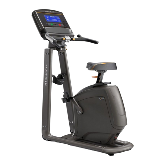
Matrix U30 Service Manual
Hide thumbs
Also See for U30:
- Manual (99 pages) ,
- Operation manual (49 pages) ,
- Assembly instructions manual (40 pages)

Related Manuals for Matrix U30


Summary of Contents for Matrix U30
- Page 1 Issue date Edition Doc No. JOHNSON Revision Edition time Page date Johnson Industries (Shanghai) Co.,Ltd U30 & U50 Service Manual Document Approval Review Editor Dora...
- Page 2 Product Browse Matrix Retail U30 Matrix Retail U50 Specification Handle Bar Type Foam wrapped PU wrapped Seat Bottom Type U30 seat with rail mount U50 seat with rail mount Resistance System Internal ECB Induction Brake...
-
Page 3: Table Of Contents
SIDE COVER REPLACEMENT ...................... 22 ECB & LCB REPLACEMENT ......................22 U50 ECB CONTROLLER REPLACEMENT ..................23 4.9 SEAT REPLACEMENT ........................23 4.10 U30 SEAT POST REPLACEMENT ....................24 4.11 U50 SEAT POST REPLACEMENT ....................24 4.12 CUP HOLDER REPLACEMENT ....................25... -
Page 4: Chapter 1: Serial Number Location
CHAPTER 1: Serial Number Location MATRIX U30/U50 BIKE FRAME... - Page 5 CHAPTER 1: Serial Number Location...
-
Page 6: Chapter 2: Console Instruction
CHAPTER 2: Console Browse XR/XIR/XER CONSOLE BROWSE Please refer to XR/XER/XIR service manual to get more details. -
Page 7: Chapter 3: Troubleshooting
CHAPTER 3: Troubleshooting 3.1 ELECTRICAL DIAGRAM U30 Frame... - Page 8 CHAPTER 3: Troubleshooting U50 Frame...
- Page 9 CHAPTER 3: Troubleshooting U30 Console Wire U30 Speed Sensor U30 Power Wire...
- Page 10 U50 Console Wire U50 Speed Sensor U50 External Powercord...
-
Page 11: Ecb/Lcb Wiring Instructions
CHAPTER 3: Troubleshooting 3.2 ECB/LCB Connections ECB Connections (U30) Console Connector Power Connector Speed sensor... - Page 12 CHAPTER 3: Troubleshooting 3.2 ECB/LCB Connections LCB Connections (U50) Power Line In Speed sensor Socket Console Socket...
-
Page 13: Troubleshooting
CHAPTER 3: Troubleshooting 3.3 TROUBLE SHOOTING 3.3.1 TROUBLESHOOTING – NO POWER TO THE CONSOLE 1) Symptom: No power to the console. Solution: a. The adaptor for this model is 12V - 2A. Check to make sure the power adaptor on the unit is correct. Test the power adaptor on a known good outlet. -
Page 14: Troubleshooting - No Resistance Or Incorrect Resistance
CHAPTER 3: Troubleshooting 3.3.3 TROUBLESHOOTING – NO RESISTANCE OR INCORRECT RESISTANCE 1) Symptom: a. The resistance is not adjustable during an exercise. b. The resistance is reversed or much too high. 2) Solution: a. Please refer to XR/XER/XIR service manual to check console for correct model selection first b. - Page 15 CHAPTER 3: Troubleshooting 3.3.3 TROUBLESHOOTING – NO RESISTANCE OR INCORRECT RESISTANCE B) If the ECB motor can move, the resistance can be adjusted. If the resistance is still too high, check the gap between orange block and the bottom. It should be within 1-2 mm. If the gap is larger than 1-2 mm, the resistance will be heavier than normal.
-
Page 16: Troubleshooting-Heart Rate Issues
CHAPTER 3: Troubleshooting 3.3.4 TROUBLESHOOTING–HEART RATE ISSUES Symptom: Heart Rate Function Does Not Work or is Reading Incorrectly Solution: 1. The heart rate grips are not connected properly or are defective. With a multi-meter set for DC voltage, place one terminal on each of the HR grip plates. The HR grip should give a voltage reading of between 0.5 and 2.0VDC. -
Page 17: Chapter 4: Part Replacement Guide
CHAPTER 4: Part Replacement Guide 4.1 CONSOLE REPLACEMENT 1) Remove the 4 screws holding the console back cover to the console (Figure A). 2) Remove the 4 screws holding the console to the frame (Figure B). 3) Disconnect all connections from the console and remove the console from console mast. (Figure C). FIGURE A FIGURE B FIGURE C... -
Page 18: Handlebar Replacement
CHAPTER 4: Part Replacement Guide 4.2 HANDLEBAR REPLACEMENT For U30 1) Remove the console (section 4.1). 2) Remove the four screws from the handlebar (Fig1). 3) Remove four screws on both heart grips (Fig2). 4) Disconnect heart rate wire from the plastic cover (Fig3). - Page 19 CHAPTER 4: Part Replacement Guide 4.2 HANDLEBAR REPLACEMENT For U50 1) Remove the console (section 4.1). 2) Remove the four screws from the handlebar (Fig1). 3) Remove four screws on both heart grips (Fig2). 4) Remove four screws which lock the quick keys (Fig3). 5) Reverse the steps one to install a new handlebar (Fig4).
-
Page 20: Pedal Replacement
CHAPTER 4: Part Replacement Guide 4.3 PEDAL REPLACEMENT 1) Using a 15mm pedal wrench, remove the pedal while firmly holding the opposite crank arm for leverage. (Figure A) Note: The left pedal is reverse-threaded. 2) Install the new pedal. FIGURE A 4.4 CRANK REPLACEMENT 1) The crank arm is fixed with a self-extracting crank bolt. -
Page 21: Console Mast Cover Replacement
CHAPTER 4: Part Replacement Guide 4.5 CONSOLE MAST COVER REPLACEMENT 1) Remove the two top covers by hand (Figure A and B). 2) Remove console mast by removing the four screws. (Figure C). FIGURE A FIGURE B FIGURE C and raise the cover out of the way 3) Remove the head cover by removing the four screws (Figure D) (Figure E). -
Page 22: Side Cover Replacement
CHAPTER 4: Part Replacement Guide 4.6 SIDE COVER REPLACEMENT 1) Remove head top covers by hand (section 4.5). 2) Remove crank arms (section 4.4). 3) Remove the screws from the covers. 4) Remove the covers. 5) Reverse steps to replace covers. 4.7 ECB &... -
Page 23: U50 Ecb Controller Replacement
CHAPTER 4: Part Replacement Guide 4.8 U50 ECB CONTROLLER REPLACEMENT 1) Disconnect wires of induction brake and any wire ties. 2) Loosen 4 fixing bolts one full turn. 3) Loosen tension bolts nuts to remove drive belt. 4) Remove 4 fixing bolts and remove ECB unit. 5) Reverse steps to replace ECB unit. -
Page 24: U30 Seat Post Replacement
CHAPTER 4: Part Replacement Guide 4.10 U30 SEAT POST REPLACEMENT 1) Remove seat pad-(section 4.7). 2) Back out pull pin (Fig1). 3) Take sleeve(Fig1)out,and then you can replace seat post. Fig1 4.11 U50 SEAT POST REPLACEMENT 1) Remove the side covers. -
Page 25: Cup Holder Replacement
CHAPTER 4: Part Replacement Guide 4.12 CUP HOLDER REPLACEMENT 1) Remove the 4 screws. (Figure A). 2) Install new cup holder.
Need help?
Do you have a question about the U30 and is the answer not in the manual?
Questions and answers
I have the stupidest question but my cord is unplugged and I cannot find teh pug in port. I have a Matrix U30
The plug-in port on a Matrix U30 is located at the CN2 Power Connector on the ECB (Electronic Control Board).
This answer is automatically generated