Advertisement
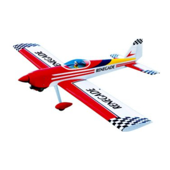
SPECIFICATION
Wingspan :
1,580mm.
Length
: 1,255 mm.
Weight
:
2.5kg.
Parts Listing required (not included).
Radio :
4 channels.
Servo :
4-5 servos.
Glow Engine : 46-55 cu.in. 2 stroke.
Instruction Manual book
62.20 in.
49.41in.
5.50lbs.
Electric Motor: BL 2826/06 OUTRUNER.
Battery: 4Cells-Li-Poly-14.8- 5.000 mAh.
Speed Control: 60A.
Propeller :
12 x 6.
Made in Vietnam.
Advertisement

Subscribe to Our Youtube Channel
Related Manuals for Black Horse Model RENEGADE


Summary of Contents for Black Horse Model RENEGADE
- Page 1 Instruction Manual book SPECIFICATION Wingspan : 1,580mm. 62.20 in. Electric Motor: BL 2826/06 OUTRUNER. Length : 1,255 mm. 49.41in. Battery: 4Cells-Li-Poly-14.8- 5.000 mAh. ...
- Page 2 Instruction Manual ITEM CODE:BH66-A This instruction manual is designed to help you build a great flying aeroplane. Please read this manual thoroughly before starting assembly of your RENEGADE. Use the parts listing below to identify all parts. WARNING. Please be aware that this aeroplane is not a toy and if assembled or used incorrectly it is capable of causing injury to people or property.
- Page 3 RENEGADE - Instruction Manual ITEM CODE:BH66-A 1. Aluminium landing gear. SAFETY PRECAUTION. 2. Wheels. + This is not a toy 3. Wheel pants. + Be sure that no other flyers are using your 4. Tai gear radio frequency. + Do not smoke near fuel 5.
- Page 4 RENEGADE - Instruction Manual ITEM CODE:BH66-A 3. Drill 1,5mm pilot holes through the block of wood for each of the four mounting screws provided with the servo. Install servo into ai- Temporary pin to leron servo tray as same as picture below.
- Page 5 RENEGADE - Instruction Manual ITEM CODE:BH66-A 1. Using a ruler & pen to draw a straight line as below picture. Mark line. 2. Locate nylon control horn, nylon con- trol horn backplates . 2 x 10 mm. ...
- Page 6 RENEGADE - Instruction Manual ITEM CODE:BH66-A 2. Attach the clevis to the outer hole in the 4. Locate one nylon servo arm, and using control horn. wire cutters,remove all but one of the arms. Using a 2mm drill bit, enlarge the third hole ...
- Page 7 RENEGADE - Instruction Manual ITEM CODE:BH66-A Secure. Repeat the procedure for the other wing half. Secure INSTALLING THE ENGINE MOUNT. THERE ARE TWO OPTIONS: 1. ELECTRIC MOTOR 2. ENGINE MOUNT. OPTION 1: ELECTRIC MOTOR. 3 x 15mm 3x 15mm C/A glue...
- Page 8 RENEGADE - Instruction Manual ITEM CODE:BH66-A 3. Carefully bend the second nylon tube up at a 45 degree angle (using a cigarette lighter). This tube will be the vent tube to the muffler. 4. Carefully bend the third nylon tube down at a 45 degree angle (using a cigarette lighter).
- Page 9 RENEGADE - Instruction Manual ITEM CODE:BH66-A 6. When satisfied with the alignment of the stopper assembly tighten the 3mm x 20mm machine screw until the rubber stopper ex- pands and seals the tank opening. Do not over tighten the assembly as this could cause the tank to split.
- Page 10 RENEGADE - Instruction Manual ITEM CODE:BH66-A 3 x 20mm Pushrod wire 100mm Secure Mark point Drill a hole 2mm Pushrod wire Right side INSTALLING THE THROTTLE SERVO. 1. Install one adjustable metal connector through the third hole out from the center of...
- Page 11 RENEGADE - Instruction Manual ITEM CODE:BH66-A Throttle Pushrod. Throttle servo After installing the adjustable metal con- nector apply a small drop of thin C/A to the bottom nut. This will prevent the con- nector from loosening during flight. COWLING. Throttle servo 1.
- Page 12 RENEGADE - Instruction Manual ITEM CODE:BH66-A 2. While keeping the back edge of the cowl flush with the marks, align the front of 3 x 12mm the cowl with the crankshaft of the engine. The front of the cowl should be positioned so the...
- Page 13 RENEGADE - Instruction Manual ITEM CODE:BH66-A Secure. 2) Using the hardware provided, mount MAIN GEAR INSTALATION. the main landing gear to the fuselage. PARTS REQUIRED 5x 35mm 5x 35mm 1) Assemble and mounting the wheel pants as shown in the following pictures.
- Page 14 RENEGADE - Instruction Manual ITEM CODE:BH66-A HORIZONTAL STABILIZER INSTALLATION. See pictures below: Bottom side Bottom side. ELEVATOR INSTALLATION. Cut the covering SERVO INSTALLATION. away from the slot. 1. Install the rubber grommets and brass collets into the elevator servo. Test fit the servo into the servo tray.
- Page 15 RENEGADE - Instruction Manual ITEM CODE:BH66-A When cutting through the cover- ing to remove it, cut with only enough pres- sure to only cut through the covering it’s self. Cutting into the balsa structure may weaken it. This could lead to possible fail-...
- Page 16 RENEGADE - Instruction Manual ITEM CODE:BH66-A 1) Drill through1.5mm (diameter) the el- evator using the control horn as a guide and screw the control horn in place. Epoxy glue 6. After the epoxy has fully cured, remove...
- Page 17 RENEGADE - Instruction Manual ITEM CODE:BH66-A Cut. E l e v a t o r pushrod Elevator pushrod. Bottom side E l e v a t o r pushrod bend and cut after. Snap keeper. RUDDER SERVO INSTALLATION. Rudder servo install as same as method of elevator servo.
- Page 18 RENEGADE - Instruction Manual ITEM CODE:BH66-A 1. Slide the rudder into the fuselage as Rudder servo. same as picture below. 2. While holding the vertical stabilizer firmly in place, use a pen and draw a line on each side of the vertical stabilizer where it meets the top of the fuselage.
- Page 19 RENEGADE - Instruction Manual ITEM CODE:BH66-A 2. Using a pen, mark the locations of the two mounting screws. Remove the tail wheel bracket and drill 1mm pilot holes at the loca- tions marked. Epoxy glue...
- Page 20 RENEGADE - Instruction Manual ITEM CODE:BH66-A Left side Right side RUDDER CONTROL HORN INSTALLA- TION. Rudder control horn install as same as the way of aileron control horn. Please see pic- tures below. C/A glue 2x12mm Control horn of Rudder.
- Page 21 RENEGADE - Instruction Manual ITEM CODE:BH66-A Drill a hole 1.5mm diameter. Secure Bend and cut after control rudder. RUDDER PUSHROD INSTALLATION. Pushrod install as same as method of pushrod wing. See pictures below: Cut. M2 lock nut.
- Page 22 RENEGADE - Instruction Manual ITEM CODE:BH66-A Bottom side. Rudder pushrod Elevator Rudder pushrod pushrod Plastic parts of elevator pushrod. INSTALLING THE SWITCH. Cut. 1) Cut out the switch hole using a modeling knife. Use a 2mm drill bit and drill out the two mounting holes through the fuselage side.
- Page 23 RENEGADE - Instruction Manual ITEM CODE:BH66-A *** Test fit the aluminium tube dihedral brace into each wing haft. The brace should slide in easily. If not, use 220 grit sand around the Battery edges and ends of the brace until it fits prop- erly.
- Page 24 RENEGADE - Instruction Manual ITEM CODE:BH66-A 3. Insert two wing panels as pictures below. Top side. Left side. BALANCING. 1) It is critical that your airplane be bal- anced correctly. Improper balance will cause your plane to lose control and crash.
- Page 25 5. Check the receiver antenna . It should be fully extended and not coiled up inside the fuselage. 6. Properly balance the propeller. We wish you many safe and enjoy- able flights with your RENEGADE.
Need help?
Do you have a question about the RENEGADE and is the answer not in the manual?
Questions and answers