
Related Manuals for Black Horse Model ROCKWELL AERO COMMANDER SHRIKE


Summary of Contents for Black Horse Model ROCKWELL AERO COMMANDER SHRIKE
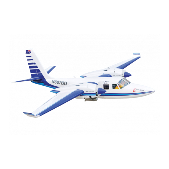
- Page 1 Instruction Manual book SPECIFICATION Wingspan : 2,060 mm 81.10 in. Length 1,460 mm 57.48 in. Weight 4.8 kg 10.56 Lbs. Radio 06 channels. Servo 07 servos. Engine 2 stroke. Made in Vietnam.
- Page 2 INSTRUCTION MANUAL. This instruction manual is designed to help you build a great flying aeroplane. Please read this manual thoroughly before starting assembly of your ROCKWELL AERO COMMANDER SHRIKE . Use the parts listing below to identify all parts. WARNING Please be aware that this aeroplane is not a toy and if assembled or used incorrectly it is capable of causing injury to people or property.
-
Page 3: Safety Precaution
ROCKWELL AERO COMMANDER SHRIKE -Item code: BH90 INSTRUCTION MANUAL. Caution: this model is not a toy! Caution! do not heat the film more than is If you are a beginner to this type of powered absolutely necessary. If the air or the iron is... -
Page 4: Installing The Aileron Servos
ROCKWELL AERO COMMANDER SHRIKE -Item code: BH90 INSTRUCTION MANUAL. A. Cowling. E. Vertical stabilizer B. Wing panel. F. Aluminium wing dihedral brace. C. Fuselage. G. Decal Sheets. D . Horizon stabilizer. REPLACEMENT SMALL PARTS 1. Air retract (Nose gear). 2. Air retracts (Main gear). - Page 5 ROCKWELL AERO COMMANDER SHRIKE -Item code: BH90 INSTRUCTION MANUAL. Bottom side Bottom side C/A glue 2) Using a modeling knife, remove the cov- ering at possition show below. C/A glue Remove covering C/A glue C/A glue...
- Page 6 ROCKWELL AERO COMMANDER SHRIKE -Item code: BH90 INSTRUCTION MANUAL. 2.INSTALLING THE AILERON CONTROL HORN. Secure 3mm x 40mm. M3 lock nut. Nilon control clasp 3) Using the thread as a guide and using masking tape, tape the servo lead to the end of the thread: carefully pull the thread out.
-
Page 7: Installing The Aileron Linkages
ROCKWELL AERO COMMANDER SHRIKE -Item code: BH90 INSTRUCTION MANUAL. INSTALLING THE AILERON LINKAGES. Installing the aileron linkages as pictures below. 70mm INSTALLING AIR RETRACTABLE LANDING GEAR. Elevator control horn 3 x 15 mm. 75mm Repeat the procedure for the other wing... - Page 8 ROCKWELL AERO COMMANDER SHRIKE -Item code: BH90 INSTRUCTION MANUAL. 75mm. Secure 3x15mm. Secure. Secure...
-
Page 9: Installing The Engine Mount
ROCKWELL AERO COMMANDER SHRIKE -Item code: BH90 INSTRUCTION MANUAL. Drill a hole 2mm diameter. Repeat the procedure for the other wing half. INSTALLING THE ENGINE MOUNT. See pictures below: FUEL TANK. INSTALLING THE STOPPER ASSEMBLY 1) The stopper has been pre-assembled at the factory. - Page 10 ROCKWELL AERO COMMANDER SHRIKE -Item code: BH90 INSTRUCTION MANUAL. 3) Carefully bend the second nylon tube 6. When satisfied with the alignment of the up at a 45 degree angle (using a cigarette stopper assembly tighten the 3mm x 20mm lighter).
-
Page 11: Installing The Engine
ROCKWELL AERO COMMANDER SHRIKE -Item code: BH90 INSTRUCTION MANUAL. 105mm Fuel tank. Mark point Drill a hole 2mm diameter. INSTALLING THE ENGINE. Locate the long piece of wire used for the throttle pushrod. One end of the wire has been pre-bend in to a “Z”... - Page 12 ROCKWELL AERO COMMANDER SHRIKE -Item code: BH90 INSTRUCTION MANUAL. Trim and cut Pushrod wire Top side 1. Slide the fiberglass cowl over the en- gine and line up the back edge of the cowl with the marks you made on the fuselage.
-
Page 13: Installing The Throttle Pushrod
ROCKWELL AERO COMMANDER SHRIKE -Item code: BH90 INSTRUCTION MANUAL. Bottom side Secure Trim and cut Secure INSTALLING THE THROTTLE PUSHROD. Install one adjustable metal connector through the third hole out from the center of one servo arm, enlarge the hole in the servo arm using a 2mm drill bit to accommodate the servo connector. - Page 14 ROCKWELL AERO COMMANDER SHRIKE -Item code: BH90 INSTRUCTION MANUAL. ELEVATOR INSTALLATION. Connector. SERVO INSTALLATION. 1. Install the rubber grommets and brass collets into the elevator servo. Test fit the servo into the servo tray. Connector. 2. Mount the servo to the tray using the mounting screws provided with your radio sys- tem.
-
Page 15: Horizontal Stabilizer
ROCKWELL AERO COMMANDER SHRIKE -Item code: BH90 INSTRUCTION MANUAL. HORIZONTAL STABILIZER. See pictures below: Top side C/A glue. C/A glue. C/A glue. C/A glue. C/A glue. 1. Draw a center line onto the horizontal stabilizer. Then slide the horizontal into the fuselage. - Page 16 ROCKWELL AERO COMMANDER SHRIKE -Item code: BH90 INSTRUCTION MANUAL. Remove covering Remove covering 3. Mark the shape of the vertical on the left and right sides onto the horizontal stabilizer using a left-tip pen. Check to mark sure the wing and stabi- lizer are paralell.
- Page 17 ROCKWELL AERO COMMANDER SHRIKE -Item code: BH90 INSTRUCTION MANUAL. Epoxy glue 6. After the epoxy has fully cured, remove the masking tape or T-pins used to hold the stabilizer in place and carefully inspect the glue joints. Use more epoxy to fill in any...
-
Page 18: Elevator Pushrod Installation
ROCKWELL AERO COMMANDER SHRIKE -Item code: BH90 INSTRUCTION MANUAL. E l e v a t o r E l e v a t o r pushrod pushrod ELEVATOR PUSHROD INSTALLATION. Elevator pushrod install as same as the way of aileron pushrod. -
Page 19: Vertical Installation
ROCKWELL AERO COMMANDER SHRIKE -Item code: BH90 INSTRUCTION MANUAL. C/A glue VERTICAL INSTALLATION. Rudder servo install as same as method of elevator servo. See picture below: C/A glue... - Page 20 ROCKWELL AERO COMMANDER SHRIKE -Item code: BH90 INSTRUCTION MANUAL. Also carefully remove the covering from the horizontal fin as below the lines which you drew as same picture below. Remove covering 1) Using a modeling knife, remove the covering from the top of the fuselage and the...
- Page 21 ROCKWELL AERO COMMANDER SHRIKE -Item code: BH90 INSTRUCTION MANUAL. 5.) When you are sure that everything is a aligned correctly, mix up a generous amount of 30 minute epoxy. Apply a thin layer to the slot in the mounting platform and to the verti- cal stabilizer mounting area.
- Page 22 ROCKWELL AERO COMMANDER SHRIKE -Item code: BH90 INSTRUCTION MANUAL. Epoxy glue Secure C/A glue C/A glue...
- Page 23 ROCKWELL AERO COMMANDER SHRIKE -Item code: BH90 INSTRUCTION MANUAL. Connector. Cut. INSTALLING NOSE AIR RETRACTABLE LANDING GEAR. 3x15mm. 65mm. C/A glue Connector.
- Page 24 ROCKWELL AERO COMMANDER SHRIKE -Item code: BH90 INSTRUCTION MANUAL. Secure Secure Secure 3 x 15mm...
- Page 25 ROCKWELL AERO COMMANDER SHRIKE -Item code: BH90 INSTRUCTION MANUAL. Secure Connector. INSTALLING SERVO USING FOR VALUE CONTROL Valve one way conector 4 way conector 3 way conector Air tank Air supply Valve one way Nose gear 4 way conector 4 way conector...
- Page 26 ROCKWELL AERO COMMANDER SHRIKE -Item code: BH90 INSTRUCTION MANUAL.
-
Page 27: Installing The Switch
ROCKWELL AERO COMMANDER SHRIKE -Item code: BH90 INSTRUCTION MANUAL. INSTALLING THE SWITCH. 1) Cut out the switch hole using a modeling knife. Use a 2mm drill bit and drill out the two mounting holes through the fuselage side. 2) Secure the switch in place using the two machine screws provided with the radio system. -
Page 28: Wing Attachment
ROCKWELL AERO COMMANDER SHRIKE -Item code: BH90 INSTRUCTION MANUAL. Tie wrap. Battery Drill a hole 3mm diameter 4 x 30mm WING ATTACHMENT. Locate the aluminium wing dihedral brace. Secure *** Test fit the aluminium tube dihedral brace into each wing haft. The brace should slide in easily. - Page 29 ROCKWELL AERO COMMANDER SHRIKE -Item code: BH90 INSTRUCTION MANUAL. See picture wing attach to fuselage. Installing the fuselage hatch as same as pic- ture below. Secure. Wing bolt. Wing bolt. Plastic parts of rudder pushrod. Cut. Drill a hole 3mm diameter...
-
Page 30: Control Throws
ROCKWELL AERO COMMANDER SHRIKE -Item code: BH90 INSTRUCTION MANUAL. BALANCING. CONTROL THROWS. 1) It is critical that your airplane be bal- 1) We highly recommend setting up a anced correctly. Improper balance will cause plane using the control throws listed.
Need help?
Do you have a question about the ROCKWELL AERO COMMANDER SHRIKE and is the answer not in the manual?
Questions and answers