Table of Contents
Advertisement
Quick Links
Advertisement
Table of Contents

Related Manuals for SciCan Statim 7000


Summary of Contents for SciCan Statim 7000
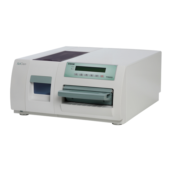
- Page 1 Statim 7000 Field Training Manual...
- Page 2 Table of Contents Table of Contents Packaging & Accessories Installation 4 – 6 User Setup 7 – 12 Service Setup 13 – 22 Cover Removal 23 – 25 Armature Removal Rear Cover Removal Chassis Parts 28 – 30 Cassette 31 – 33 Error Codes 34 –...
-
Page 3: Packaging & Accessories
Statim 7000 Packaging & Accessories Exhaust Tubings Stat-Dri Power Cord Op Manual O-ring Lube Cassette (on bottom of box) Water Reservoir Waste Bottle Condenser Bottle 2 Water Filters... -
Page 4: Installation
Statim 7000 Installation Connect the Power Cord and the Exhaust Tubings to the rear of the Statim. Air Filter Power Switch Drain Tube Push In Fitting Push In Fitting Power Cord Connection Connect the Exhaust Tubings to the large fittings on the Condenser Bottle &... -
Page 5: Installation
Connect bottle together using Quick Disconnect Coupling. Direct to Drain Waste Bottle Direct to Drain Waste Bottle Installation Instructions... - Page 6 Insert Water Filter or Bypass Cartridge. Biological Filter Insert Water Reservoir Note: The Biological Filter is accessible behind the Water Reservoir.
-
Page 7: User Setup
Statim 7000 User Setup User setup mode – To initially setup your Statim Hold down the Stop button and turn the unit ON. If unit is already ON. Hold down the Stop Button and the Air Dry Only Button simultaneously. - Page 8 Language Setup – Display information in your desired language N. A. ENGLISH Available Languages N. A. English (North American English) U. K. English (United Kingdom English) Francais (French) Deutsch (German) Espanol (Spanish) Italiano (Italian) Dansk (Danish) Portugues Nederlands Japanese Svenska (Swedish) Polski (Polish) Magyar (Hungarian) Cesky (Czech)
- Page 9 Drying – Unwrapped – Set Unwrapped Cycle drying time between 0 & 30 minutes >Drying - Unwrapped Time: 12 minutes Keypad: Unwrapped Increase time by one minute Wrapped Decrease time by one minute Rubber and Plastics Save and return to main menu Stop Save &...
- Page 10 Water Quality – Display detected water quality >Water quality CD= x.xuS/NNN/y.yppm Screen Representation Water conductivity in uS (micro-Siemens) Water conductivity in ADC (Analog to Digital converter) counts (0…255) Water quality in ppm (parts per million) Keypad: Rubber and Plastics Return to main menu Stop Exit menu to normal mode of operation Last Printout...
- Page 11 Printer user ° char SciCan Suggested End Of Line Serial Port Bit External Printers CR/LF Rate Epson CR/LF 9600 248 [0xF8] TM-U220D (C31C515603) Citizen 9600 IDP-3110-40 RF 120B Star Micro 9600 210 [0xd2] SP212FD42-120 Star Micro CR/LF 9600 210 [0xd2]...
- Page 12 Steri. End buzzer – Set length of time buzzer will sound a end of sterilization >Steri. End buzzer Keypad: Unwrapped Select next value Wrapped Select previous value Rubber and Plastics Save & Return to main menu Stop Save & exit menu to normal mode of operation Air Filter Warning –...
-
Page 13: Service Setup
Statim 7000 Service Setup Service setup mode – To enter the Service Setup Mode, turn power switch ON while holding down Unwrapped and Wrapped buttons. The Service Setup Mode is password protected; a password must be entered to continue. The default password is Unwrapped, Wrapped, Rubber and Plastics, Stop buttons pressed in this order. - Page 14 Calibration – Select calibration to run chamber and validation thermocouple calibration cycles only. Note: See page 38 for validation thermocouple calibration procedure. Time/Date Setup Mode – Set the proper time and date 18:00 07/09/2008 HH:MM MM/DD/YYYY Keypad: Unwrapped Increase current field (the flashing value on the display) Wrapped Decrease current field (the flashing value on the display) Rubber and Plastics...
- Page 15 Values larger than this trigger “Bad water quality” error G.GG Water conductivity circuit gain default 1.00 Note: Statim 7000 does not use the conductivity reading to trigger the “No Water, Refill Reservoir” message. There is a float sensor for that. Keypad: Unwrapped...
- Page 16 Water Cnd Tmp Comp - To enable or disable water conductivity temperature compensation >Water Cnd Tmp Comp Keypad: Unwrapped Select next option Second line shows the new value Wrapped Select previous option. Second line shows the new value Rubber and Plastics Select and return to main menu Stop Exit, without saving, to normal mode of operation...
- Page 17 Devices Test On/Off – Toggle the unit’s devices on or off >Devices Test On/Off Pump Off Valve Off Compressor Off Yellow LED Off Extra 1L Off Extra 2L Off Valve 2 Off Fan Off Keypad: Unwrapped Select next option. Second line shows the new value Wrapped Select previous option.
- Page 18 Select previous option. Second line shows the new value Rubber and Plastics Save & exit to main menu Stop Exit and return to normal mode of operation Printer user ° char SciCan Suggested End Of Line Serial Port Bit External Printers CR/LF Rate...
- Page 19 Serial Port Bit Rate – Choose bit rate for device connected to the serial port (Used with Printer) Serial Port Bit Rate 9600 19200 57600 115200 1200 2400 4800 If USB FLASH/MSD is selected as the RS232 device, a Serial Port Bit Rate selection of 9600 will be required for the Data Logger to be operational.
- Page 20 Drying – Unwrapped – Set Unwrapped Cycle drying time between 0 & 30 minutes >Drying - Unwrapped Time: 12 minutes Keypad: Unwrapped Increase time by one minute Wrapped Decrease time by one minute Rubber and Plastics Save and return to main menu Stop Save &...
- Page 21 Air Filter Warning – Reset warning indicator when Air Filter is replaced. >Air Filter Warning Do not Reset Yes, Reset Water Filter – Set Statim for Water Filter or Water Bypass Cartridge >Water Filter Installed Not Installed Replace Filter – Reset Statim when Water Filter is replaced. >Replace Filter Do not replace Yes, replace...
- Page 22 Backup NVRAM – Saves a copy of the unit’s current settings >Backup NVRAM Keypad: Unwrapped Select next option Second line shows the new value Wrapped Select previous option. Second line shows the new value Rubber and Plastics Select and return to main menu Stop Exit, without saving, to normal mode of operation Restore NVRAM...
-
Page 23: Cover Removal
Statim 7000 Cover Removal 1. With the unit off, unplug the power cord from the wall outlet and remove the cassette and reservoir from the unit. 2. Remove the water filter or water bypass cartridge (if the unit is using distilled water) from the reservoir area. - Page 24 6. Push this tab to the left to unlock the LCD/keypad from the cover. 7. Place the LCD/keypad on top of the armature so that it is out of the way as you remove the cover. 8. Release the cover retention clip by reaching inside the cover though the LCD opening and lift up on the tap located on the left most side of the...
- Page 25 9. Push the cover all the way forward to slide it off from the front. 10. To replace the cover. Place the cover back on to the unit about 1 inch away from the back. Once the chassis hooks engage with the cover, push the cover towards the back until the back of the cover is in line with the back of the chassis...
-
Page 26: Armature Removal
Armature Removal Removed 2 screws in lower left and right corners of Armature and loosen alignment screw in top center of Armature. Armature Alignment Screw Armature Screw Armature Screw Armature is mounted on 2 rails which will allow the Armature to slide easily. Slide Armature forward and remove using two hands. -
Page 27: Cover Removal
Rear Cover Removal Remove 3 screws from bottom of rear cover. Screw Screw Screw Screw Remove 3 screws from top of rear cover. Screw Screw Disconnect black and white wires from Fan Fan Wires Disconnect Biological Filter Tubings Biological Filter Tubings... -
Page 28: Chassis Parts
Statim 7000 Chassis Parts Biological Filter 01-102119S Reservoir Inlet Armature 01-110493S 01-110496S Thermocouple Validation 01-110515S Armature Microswitch 01-110502S PCB RFID Board 01-110483S... - Page 29 Reservoir Inlet Assembly 01-110493S Water Filter Ports Sensor Reservoir 01-110492S Water Reservoir Port Compressor 01-110478S Pump 01-110471S...
- Page 30 Auxiliary Heater 01-110474S Boiler Solenoid Chamber 01-110472S Valve 2 01-110527S Push In Fitting Air Filter 01-110503S 01-101652S Solenoid Validation Valve 1 01-110528S Power Switch 01-110504S Line Filter 01-110505S Plug Drain Tubing 01-104343S...
-
Page 31: Cassette
Statim 7000 Cassette Perforated Rack Steam Deflector Outlet Coupling Outlet Coupling O-Ring Seals Inlet Coupling Exhaust Duct Exhaust Duct Screen Inlet Coupling O-Ring Seals... - Page 32 Cassette Lid Cassette Complete 7000 Internal Dimensions: Part #01-110288S 13.7" x 8.6" x 2.5" Cassette Lid 7000 Part #01-110290S Cassette Tray 7000 Part #01-110289S Cassette Tray Cassette Lid Cassette Lid Handle Handle Cassette Tray Part #01-110329S Handle Cassette Tray Handle Part #01-110330S Cassette Seal Kit (not shown) Part #01-110327S...
-
Page 33: Cassette
Cassette Tray Exhaust Duct Part #01-110297S Cassette Steam Deflector Part #01-110825S Cassette Tray Exhaust Duct Cassette Steam Deflector Filter Exhaust Duct Insert Part #01-106848S Filter Exhaust Cassette Steam Deflector Clip Duct Insert Cassette Steam Part #01-110824S Deflector Clip... -
Page 34: Error Codes
Statim 7000 Error Codes Cycle Fault Description of Fault Suggested steps for Correction of Fault Number Cycle Fault #1 The Cassette temperature May be caused by a large cassette leak in failed to reach 95°C within a conjunction with an extremely large load or time-out period. - Page 35 Cycle Fault #14 The steam temperature Check for faulty PCB or defective Solid raised above the high State Relay. threshold. Cycle Fault #15 The cassette temperature Check for a clogged Filter Screen in the raised above the high Exhaust Duct in the Cassette Tray, a threshold during the kinked or pinched Exhaust Tubing from sterilization phase of the...
- Page 36 Cycle Fault #26 The sterilization phase has May be caused by improper Validation failed to start within 3 Thermocouple calibration, weak Water minutes of the cassette Pump or faulty Solenoid Valve. reaching sterilization temperature. CF26 is displayed when it occurred in 3 consecutive cycles (Cycle Interrupted is displayed for the first two cycles).
- Page 37 “No No communication between May be Microprocessor or EEPROM not Configuration EEPROM and installed properly. Replace Microprocessor EEPROM” Microprocessor. kit. Message: Printer Printer is not printing. Check for paper jam or defective Printer. Fault (if optional printer is installed) “Cycle Aborted” This error message is displayed on the printout only, followed by the...
- Page 38 “Press Stop To This message is displayed Reset” for all error faults. The user must press the Stop button on the keypad to reset the unit: otherwise the user will be unable to initiate another cycle. “Order Water This message is displayed Order Water Filter Cartridge part #SCWF1 Filter Expiring when the water quality...
-
Page 39: Water Conductivity Circuit Calibration
Water conductivity circuit gain default 1.00 Note: Statim 7000 does not use the conductivity reading to trigger the “No Water, Refill Reservoir” message. There is a float sensor for that. By pressing the Rubber and Plastics Key the selection moves between H and G. -
Page 40: Validation Thermocouple Calibration
Statim 7000 Validation Thermocouple Calibration 1. Turn power switch ON while holding down Unwrapped and Wrapped keys to enter Service Mode. 2. The Service Mode is password protected, enter password to continue, default password is: Unwrapped, Wrapped, Rubber and Plastics and Stop keys pressed in this order. If the password has been changed the backdoor password is, Unwrapped, Wrapped, Unwrapped, Wrapped buttons pressed in this order. -
Page 41: Validation Thermocouple Calibration
6. The Validation thermocouple self-calibration will start by entering the heating up phase and the screen will change for the Voltage Reading calibration. Voltage Calibration V=VVV VCAL=CCC Screen Representation VVV = Voltage measured by unit CCC = Voltage calibration offset Keypad function at this time: Unwrapped Key: Increase current field...
Need help?
Do you have a question about the Statim 7000 and is the answer not in the manual?
Questions and answers