Table of Contents
Advertisement
TopPage
[1]
PRODUCT OUTLINE . . . . . . . . . . . . . . . . . . . . . . . . . . . . . . . . . . . 1-1
[2]
SPECIFICATIONS. . . . . . . . . . . . . . . . . . . . . . . . . . . . . . . . . . . . . . 2-1
[3]
UNPACKING AND INSTALLATION. . . . . . . . . . . . . . . . . . . . . . . . . 3-1
* For how to unpacking and installation, refer to the installation manual.
[4]
EXTERNAL VIEWS AND INTERNAL STRUCTURES . . . . . . . . . . 4-1
[5]
OPERATIONAL DESCRIPTION . . . . . . . . . . . . . . . . . . . . . . . . . . . 5-1
[6]
DISASSEMBLY AND ASSEMBLY. . . . . . . . . . . . . . . . . . . . . . . . . . 6-1
[7]
MAINTENANCE . . . . . . . . . . . . . . . . . . . . . . . . . . . . . . . . . . . . . . . 7-1
[8]
ADJUSTMENTS . . . . . . . . . . . . . . . . . . . . . . . . . . . . . . . . . . . . . . . 8-1
[9]
SELF DIAG MESSAGE AND TROUBLE CODE . . . . . . . . . . . . . . . 9-1
[10] ELECTRICAL SECTION . . . . . . . . . . . . . . . . . . . . . . . . . . . . . . . . 10-1
Parts marked with "
" are important for maintaining the safety of the set. Be sure to replace these parts with
specified ones for maintaining the safety and performance of the set.
SERVICE MANUAL
DIGITAL FULL COLOR
MULTIFUNCTIONAL SYSTEM OPTION
SADDLE STITCH FINISHER
PUNCH MODULE
PAPER PASS UNIT
MX-FN10
MX-PNX5 A/B/C/D
MX-RBX3
MODEL
CONTENTS
SHARP CORPORATION
CODE: 00ZMXFN10/S1E
This document has been published to be used
for after sales service only.
The contents are subject to change without notice.
Advertisement
Table of Contents

Related Manuals for Sharp MX-FN10


Summary of Contents for Sharp MX-FN10
- Page 1 DIGITAL FULL COLOR MULTIFUNCTIONAL SYSTEM OPTION SADDLE STITCH FINISHER PUNCH MODULE PAPER PASS UNIT MX-FN10 MX-PNX5 A/B/C/D MX-RBX3 MODEL CONTENTS PRODUCT OUTLINE ........1-1 SPECIFICATIONS.
- Page 2 1. Finisher/saddle unit and Punch unit ....8-1 1. MX-FN10 ........2-1 2.
-
Page 3: Product Outline
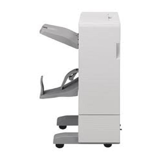
DATA SECURITY KIT DATA SECURITY KIT MX-FR10U MX-FR10 MX-USX1 MX-US50 MX-AMX2 MX-KBX1 SHARPDESK SHARPDESK EXTERNAL Memory 5 LICENSE KIT 100 LICENSE KIT ACCOUNT MODULE MX-USX5 MX-USA0 MX-AMX3 EXPANSION SHARPDESK MEMORY BOARD 10 LICENSE KIT MX-SMX3 MX-US10 MX-FN10 PRODUCT OUTLINE 1 – 1... -
Page 4: Specifications
10 sets (11 to 15 sheets), 15 sets (6 to 10 sheets), 20 sets (1 to 5 sheets) D. Consumable parts Name Content Life Product name Staple cartridge Staple cartridge x 3 5000 x 3 MX-SCX1 Staple cartridge (for saddle) Staple cartridge x 3 2000 x 3 AR-SC3 MX-FN10 SPECIFICATIONS 2 – 1... -
Page 5: Mx-Pnx5 A/B/C/D
A: 801mm (MX-PNX5A) B: 123mm (MX-PNX5C) B: 123mm 8.0mm 6.5mm 2/3 holes 2 holes A: 1081mm 4 holes A: 701mm (MX-PNX5B) B: 123mm (wide) B: 123mm (MX-PNX5D) C: 211mm 3 holes A: 701mm B: 123mm MX-FN10 SPECIFICATIONS 2 – 2... -
Page 6: Mx-Rbx3
Cable connection from the finisher Control: Controlled by the communication command from the main unit through the finisher. Installation/maintenance Installed by service personnel Optional detection Auto detection supported Packaged items Parts for mounting, installation cautionary note MX-FN10 SPECIFICATIONS 2 – 3... -
Page 7: External Views And Internal Structures
Saddle No. 3 transport roller Paper holding lever Paper pushing plate Scrabble belt Saddle section Saddle No. 1 transport roller Paper lead edge pushing plate Gripper unit Saddle stitch tray Edge binding staple unit MX-FN10 EXTERNAL VIEWS AND INTERNAL STRUCTURES 4 – 1... - Page 8 Paper exit front roller Paper exit front roller Inlet port rear roller Inlet port rear roller shaft Inlet port roller Inlet port roller Reverse flapper Paper exit roller Upper guide flapper MX-FN10 EXTERNAL VIEWS AND INTERNAL STRUCTURES 4 – 2...
- Page 9 FR direction becomes HI level. TOPCOVS FCD2 Finisher Cover Detector 2 Photointerrupter Detection of open/close of the When the cover is closed, TP15 upper JAM release cover becomes LO level. MX-FN10 EXTERNAL VIEWS AND INTERNAL STRUCTURES 4 – 3...
- Page 10 Detection of retraction of the paper surface lever. Detection of the paper surface position on the load tray. Detection of a high position of the paper surface on the load tray. MX-FN10 EXTERNAL VIEWS AND INTERNAL STRUCTURES 4 – 4...
- Page 11 Finisher Control PWB Controls the finisher. BNDSTPLMOT Finisher Staple Motor Drives the stapling mechanism. (Stapler unit built-in motor) STPLMOT FSDSM Finisher Saddle Staple Motor Drives the stapling mechanism. (Stapler unit built-in motor) MX-FN10 EXTERNAL VIEWS AND INTERNAL STRUCTURES 4 – 5...
- Page 12 Detects the home position of the When at home position, TP49 on the Position Sensor punch position horizontal resist control PWB of the finisher becomes correction mechanism. HI level. (2) Motor and PWB MX-FN10 EXTERNAL VIEWS AND INTERNAL STRUCTURES 4 – 6...
- Page 13 Interface reverse path solenoid Drive of the flapper which selects the path in the finisher and the reverse path PDCF Interface fan Temperature rise protection fan in the finisher inlet port section MX-FN10 EXTERNAL VIEWS AND INTERNAL STRUCTURES 4 – 7...
-
Page 14: Operational Description
When the paper rear edge goes out of the paper exit roller, the speed of the transport motor 2 is changed to the paper exit speed of the main unit. When paper is stored in the process tray, the alignment plate reciprocates to align paper. MX-FN10 OPERATIONAL DESCRIPTION 5 – 1... -
Page 15: Rear On Position Staple Mode
The inlet port sensor turns OFF and the paper rear edge reaches the specified position. Then the speed of the transport motor is changed to the paper exit speed of the main unit. MX-FN10 OPERATIONAL DESCRIPTION 5 – 2... -
Page 16: Position Staple Mode
Then the speed of the transport motor and When paper is stored in the process tray, the alignment plate the transport motor 2 is changed to the inside-the-main unit reciprocates to align paper. speed. MX-FN10 OPERATIONAL DESCRIPTION 5 – 3... -
Page 17: Saddle Motor
2 is tem- porarily stopped. Then the transport motor 2 reverses to store paper in the saddle process tray. After stapling, the paper bundle is discharged to the stack tray by the gripper. MX-FN10 OPERATIONAL DESCRIPTION 5 – 4... - Page 18 Reception of paper in the saddle process tray is repeated until After completion of stapling, the paper stopper is lowered to the specified number of sheet for a bundle is stacked. (1 - 5) shift the paper bundle to the paper folding position. MX-FN10 OPERATIONAL DESCRIPTION 5 – 5...
-
Page 19: Punch Process
When paper is stopped, the punch motor is booted to punch at the paper rear edge. After completion of punching, the transport motor and the transport motor 2 are booted to start paper transport, execut- ing the specified after-process. MX-FN10 OPERATIONAL DESCRIPTION 5 – 6... -
Page 20: Disassembly And Assembly
Remove the saddle finisher from the main unit. Remove the fixing lever. 1. Saddle finisher A. External outfit control items (1) Load tray Remove the load tray. (3) Saddle tray Remove the saddle tray. MX-FN10 DISASSEMBLY AND ASSEMBLY 6 – 1... - Page 21 Remove the rear cabinet upper. (See (5).) Remove the upper door. (5) Rear cabinet upper Remove the rear cabinet upper. (8) Right cabinet Remove the front cabinet. (See (4).) Remove the rear cabinet. (See (5).) Remove the right cabinet. MX-FN10 DISASSEMBLY AND ASSEMBLY 6 – 2...
- Page 22 Disconnect two connectors on the left side of the side guide upper. NOTE: When assembling, place the polyester film (2 positions) on each side of the side guide lower and attach. MX-FN10 DISASSEMBLY AND ASSEMBLY 6 – 3...
- Page 23 Remove the center binding stapler earth wire fixing screw. Slide the stapler to the front, and remove the connector and the earth wire fixing screw. Remove the center binding stapler unit fixing screw. (5 posi- tions) MX-FN10 DISASSEMBLY AND ASSEMBLY 6 – 4...
- Page 24 Slide the stapler to the front. Remove the latch for connection of the main unit. (4) Saddle pushing plate motor gear box removal Remove the grip, the E-ring, and the bearing which are fixing each gear shaft. MX-FN10 DISASSEMBLY AND ASSEMBLY 6 – 5...
- Page 25 C. PWB section (1) Saddle finisher control PWB Remove the rear cabinet upper. (See A-(5).) Remove the PWB fixing screw, and disconnect each connec- tor, release the PWB holding pawl, and remove the PWB. MX-FN10 DISASSEMBLY AND ASSEMBLY 6 – 6...
-
Page 26: Paper Transport Section (Mx-Rbx3)
Pull out the paper pass unit, and remove the screw. (3) Upper Guide Flapper Remove the paper pass unit. Open the upper transport unit, remove each parts, and remove the reverse gate. Free the lock, to remove the paper pass unit. MX-FN10 DISASSEMBLY AND ASSEMBLY 6 – 7... - Page 27 Disconnect the connector, then remove the interface transport motor. * Adjust so that the distance between the lower guide and the upper guide flapper is 22mm with the solenoid plunger pushed in. Install the entry reverse pass solenoid. 22mm MX-FN10 DISASSEMBLY AND ASSEMBLY 6 – 8...
- Page 28 Remove the paper pass unit. Remove the bottom cover. (See (4).) Remove the front cover. (See (6).) Remove the upper guide unit. (See (7).) Remove each parts, and remove the pre entry roller. MX-FN10 DISASSEMBLY AND ASSEMBLY 6 – 9...
- Page 29 Remove each parts, and remove the reverse flapper. (2) Paper Pass PWB Remove the paper pass unit. Remove the reverse tray. (See B-(1)) Remove the left cover. (See C-(1).) Remove allen screw, remove the interface PWB, then remove the connector. MX-FN10 DISASSEMBLY AND ASSEMBLY 6 – 10...
-
Page 30: Punch Section
Remove the upper cover. (Remove two screws.) Remove the shift. Remove the rear blinding cover. (Remove two screws.) Remove the screw and the motor. Remove the jam process knob, the screw, and the sensor holding part. MX-FN10 DISASSEMBLY AND ASSEMBLY 6 – 11... - Page 31 Remove the screw which is fixing the sensor cover. Remove the screw which is fixing the dust sensor. Pull out in the arrow direction [1], and remove in the arrow Remove the dust sensor in the arrow direction. direction [2]. MX-FN10 DISASSEMBLY AND ASSEMBLY 6 – 12...
- Page 32 Remove the registration sensor in the same direction as the cover. Remove two screws. Remove the spring in the arrow direction. Remove the harness duct in the arrow direction. MX-FN10 DISASSEMBLY AND ASSEMBLY 6 – 13...
-
Page 33: Maintenance System Table
Replacement reference: Replace the unit at every 100K staple. Punch unit Replacement reference: Replace the unit at every 1000K. Staple cartridge User replacement for every 5000pcs. Staple cartridge for saddle User replacement for every 2000pcs. MX-FN10 MAINTENANCE 7 – 1... -
Page 34: Adjustments
Small value: The staple STAPLE Staple binding position 35 - 62 (Two position is shifted to the PITCH adjustment (Two positions positions rear side from the center. pitch) center) PUNCH Punch center adjustment 35 - 65 CENTER MX-FN10 ADJUSTMENTS 8 – 1... -
Page 35: Punch Unit (Option)
(Since the first cycle includes the first lighting of the LED, count the number of flashing in the second cycle.) Turn OFF the power of the punch unit. Set all the DIP switches to OFF, and terminate the opera- tion. MX-FN10 ADJUSTMENTS 8 – 2... - Page 36 The DIP switch setting and the target adjustment sensors are shown in the table below. DIP switch Adjustment execution sensor Transport system, paper edge detection system sensor (collective) Punch dust detection system MX-FN10 ADJUSTMENTS 8 – 3...
-
Page 37: Self Diag Message And Trouble Code
PWB. If the trouble still Check & Check conduction between connector remains, replace the punch control PWB. Remedy terminals. If there is no conduction, replace the electric cable. MX-FN10 SELF DIAG MESSAGE AND TROUBLE CODE 9 – 1... -
Page 38: Transport Section Except For The Saddle
3.3V 5% when finisher control PWB. If the trouble still interrupted. If the voltage is outside the range, remains, replace the finisher control PWB. replace the sensor. MX-FN10 SELF DIAG MESSAGE AND TROUBLE CODE 9 – 2... -
Page 39: Load Tray
Electric cable, connector trouble Remedy terminals. If there is no conduction, replace Check & Check conduction between connector the electric cable. Remedy terminals. If there is no conduction, replace the electric cable. MX-FN10 SELF DIAG MESSAGE AND TROUBLE CODE 9 – 3... -
Page 40: Staple Unit
PWB. If the trouble remains even If the voltage is outside the range, replace the tough the sensor operates properly in the switch. sensor check, replace the finisher control PWB. MX-FN10 SELF DIAG MESSAGE AND TROUBLE CODE 9 – 4... -
Page 41: Saddle Staple Unit
Case1 Cause Saddle pushing plate motor trouble sensor check, replace the finisher control Check & Check conduction of the coil. If there is no PWB. Remedy conduction, replace. MX-FN10 SELF DIAG MESSAGE AND TROUBLE CODE 9 – 5... -
Page 42: Other Sections
If the voltage is outside the range, replace the sensor. Case2 Cause Electric cable, connector trouble Check & Check conduction between connector Remedy terminals. If there is no conduction, replace the electric cable. MX-FN10 SELF DIAG MESSAGE AND TROUBLE CODE 9 – 6... -
Page 43: Electrical Section
Saddle stitch staple unit BNDR3S (FSRHS) BNDBRDCLKS Commu- (FSMRS) nication JOGPOSS circuit (FSSSW2) GRPOUTS (FPDD) DC24V JOINTS (FCD) BNDSTPRESW SW open/ (FSSCS) close detection FDOORSW (FSSW1) circuit STPLSAFESW (FSSSW1) DC5V DC24V DC24V DC5V DC5V MX-FN10 ELECTRICAL SECTION 10 – 1... - Page 44 (FPPS) (FPM) Driver PNCHHP circuit (FPCHPS) SLDMOT (FPSM) PNCHCLK (FPMRS) EEPROM SLDHP (FPHPS) Sensor input PBA-REGPTR (FPTS, FPES1 - 4) circuit PBA-REGLED (FPTS, FPES1 - 4) PBA-DUSTPTR (FPDFS) PBA-DUSTLED (FPDFS) DC24V DC24V DC5V DC5V MX-FN10 ELECTRICAL SECTION 10 – 2...
-
Page 45: Wiring Diagram
2. Wiring diagram A. MX-FN10 (1) MX-FN10 (1/5) MX-FN10 ELECTRICAL SECTION 10 – 3... - Page 46 (2) MX-FN10 (2/5) MX-FN10 ELECTRICAL SECTION 10 – 4...
- Page 47 (3) MX-FN10 (3/5) MX-FN10 ELECTRICAL SECTION 10 – 5...
- Page 48 (4) MX-FN10 (4/5) MX-FN10 ELECTRICAL SECTION 10 – 6...
- Page 49 (5) MX-FN10 (5/5) MX-FN10 ELECTRICAL SECTION 10 – 7...
- Page 50 B. MX-RBX3 MX-FN10 ELECTRICAL SECTION 10 – 8...
- Page 51 C. MX-PNX5 A/B/C/D MX-FN10 ELECTRICAL SECTION 10 – 9...
- Page 52 Memo...
- Page 53 Memo...
- Page 54 LEAD-FREE SOLDER The PWB’s of this model employs lead-free solder. The “LF” marks indicated on the PWB’s and the Service Manual mean “Lead-Free” solder. The alphabet following the LF mark shows the kind of lead-free solder. Example: <Solder composition code of lead-free solder> Solder composition Solder composition code Solder composition...
- Page 55 CAUTION FOR BATTERY REPLACEMENT (Danish) ADVARSEL ! Lithiumbatteri – Eksplosionsfare ved fejlagtig håndtering. Udskiftning må kun ske med batteri af samme fabrikat og type. Levér det brugte batteri tilbage til leverandoren. (English) Caution ! Danger of explosion if battery is incorrectly replaced. Replace only with the same or equivalent type recommended by the manufacturer.
- Page 56 Adobe, the Adobe logo, Acrobat, and the Acrobat logo are trademarks of Adobe Systems Incorporated. PCL is a registered trademark of the Hewlett-Packard Company. Sharpdesk is a trademark of Sharp Corporation. All other trademarks and copyrights are the property of their respective owners. SHARP CORPORATION...
Need help?
Do you have a question about the MX-FN10 and is the answer not in the manual?
Questions and answers