
Subscribe to Our Youtube Channel
Related Manuals for Aaeon AEC-6913


Summary of Contents for Aaeon AEC-6913
- Page 1 E m b e d d e d C o n t r o l l e r A E C - 6 9 1 3 AEC-6913 Fanless Embedded Controller ® Intel Atom™ D2550 1.86GHz Processor 2 PCI / PCI-E[x1] 2 GbE/ 8 COMs/ 4 USB2.0, 2 USB3.0 AEC-6913 Manual 4 August 5, 2015...
- Page 2 AAEON assumes no liabilities resulting from errors or omissions in this document, or from the use of the information contained herein. AAEON reserves the right to make changes in the product design without notice to its users.
- Page 3 E m b e d d e d C o n t r o l l e r A E C - 6 9 1 3 Acknowledgments • AMI is a trademark of American Megatrends Inc. • ™ CFast is a trademark of the Compact Flash Association. •...
- Page 4 A E C - 6 9 1 3 Packing List Before you begin operating your PC, please make sure that the following materials have been shipped: AEC-6913 Embedded Controller Phoenix Power Connector M3 x 4mm Screws ...
- Page 5 E m b e d d e d C o n t r o l l e r A E C - 6 9 1 3 Safety & Warranty 1. Read these safety instructions carefully. 2. Keep this user's manual for later reference. 3.
- Page 6 E m b e d d e d C o n t r o l l e r A E C - 6 9 1 3 The equipment does not work well, or you cannot get it to work according to the user’s manual. The equipment has been dropped and damaged.
- Page 7 E m b e d d e d C o n t r o l l e r A E C - 6 9 1 3 Below Table for China RoHS Requirements 产品中有毒有害物质或元素名称及含量 AAEON Boxer/ Industrial System 有毒有害物质或元素 部件名称 铅...
-
Page 8: Table Of Contents
E m b e d d e d C o n t r o l l e r A E C - 6 9 1 3 Contents Chapter 1 General Information 1.1 Introduction ..............1-2 1.2 Features ..............1-3 1.3 Specifications ............1-4 Chapter 2 Hardware Installation 2.1 Jumpers and Connectors of Main Board.... - Page 9 E m b e d d e d C o n t r o l l e r A E C - 6 9 1 3 2.18 RS-232/422/485 Pin Definition (COM2) ....2-9 2.19 RS-232 Header (COM3) ......... 2-10 2.20 RS-232 Header (COM4) ......... 2-10 2.21 RS-232 Header (COM5) .........
-
Page 10: Chapter 1 General Information
E m b e d d e d C o n t r o l l e r A E C - 6 9 1 3 Chapter General Information Chapter 1 General Information... -
Page 11: Introduction
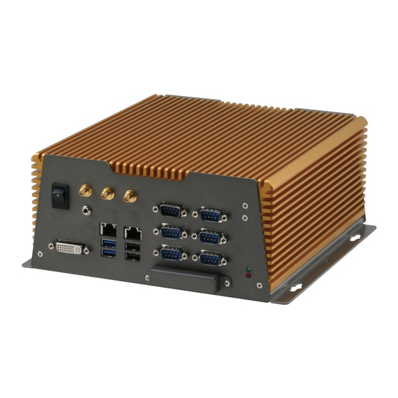
Processing, Fleet Management, Data Management. AEC-6913 equips a high efficiency heat conduction mechanism. The AEC-6913 is compact in size but has attractive and flexible extension capabilities such as 4 USB 2.0 ports and 2 USB 3.0 ports, VGA, Audio, 8 COM ports, and 2 PCI or PCI-E[x1]. -
Page 12: Features
E m b e d d e d C o n t r o l l e r A E C - 6 9 1 3 1.2 Features Fanless Design ® Intel Atom™ D2550 Processor ® Intel NM10 Chipset ... -
Page 13: Specifications
E m b e d d e d C o n t r o l l e r A E C - 6 9 1 3 1.3 Specifications ® CPU Intel Atom™ D2550 Processor, 1.86 GHz ® Chipset Intel NM10 ... - Page 14 E m b e d d e d C o n t r o l l e r A E C - 6 9 1 3 Rear I/O USB Host USB 2.0 x 2 - Serial Port Insolated RS-232/422/485 x 2 (3KV, jumper selection) Isolated DIO x 1 (4 in and 4 out, 3KV) -...
- Page 15 E m b e d d e d C o n t r o l l e r A E C - 6 9 1 3 temperature Storage and RAM) Storage Temperature F ~ 158 F (-20 C ~ 70 ...
- Page 16 E m b e d d e d C o n t r o l l e r A E C - 6 9 1 3 ISOLATION CAN1 ISOLATION CAN2 DC-IN V+ V- FG ISOLATION COM2 ISOLATION COM1 ISOLATION DIO USB 2.0 DC 9~30V COM7...
-
Page 17: Chapter 2 Hardware Installation
E m b e d d e d C o n t r o l l e r A E C - 6 9 1 3 Chapter Hardware Installation Chapter 2 Hardware Installation... -
Page 18: Jumpers And Connectors Of Main Board
E m b e d d e d C o n t r o l l e r A E C - 6 9 1 3 2.1 Jumpers and Connectors of Main Board Component Side Solder Side 2 - 2 Chapter 2 Hardware Installation... -
Page 19: Dimension
E m b e d d e d C o n t r o l l e r A E C - 6 9 1 3 2.2 Dimension LINE IN ISOLATION CAN1 LAN2 DVI-D ISOLATION CAN2 DVI-I USB3.0 DC-IN V+ V- FG ISOLATION COM2 ISOLATION COM1 ISOLATION DIO USB 2.0... -
Page 20: List Of Jumpers
E m b e d d e d C o n t r o l l e r A E C - 6 9 1 3 2.3 List of Jumpers The board has a number of jumpers that allow you to configure your system to suit your application. - Page 21 E m b e d d e d C o n t r o l l e r A E C - 6 9 1 3 Mini Card Connector With onboard SIM CFast™ Connector(SATA 3.0) CN10,CN11 SATA Power CN12 USB2.0 X2 / LAN1 Connector CN13 USB3.0 X2 / LAN2 Connector CN17...
-
Page 22: Setting Jumpers
E m b e d d e d C o n t r o l l e r A E C - 6 9 1 3 2.5 Setting Jumpers You configure your card to match the needs of your application by setting jumpers. -
Page 23: Isolated Com1, Com2 Rs-232/485/422 Selection (Jp3, Jp4)
E m b e d d e d C o n t r o l l e r A E C - 6 9 1 3 2.6 Isolated COM1, COM2 RS-232/485/422 Selection (JP3, JP4) JP3,JP4 Function RS-232 1-2,3-4,5-6 close RS-422 3-4 close , 1-2 5-6 open RS-485 5-6 close , 1-2 3-4 open... -
Page 24: Sata Power (Cn10~Cn11)
E m b e d d e d C o n t r o l l e r A E C - 6 9 1 3 2.12 SATA Power (CN10~CN11) Signal +12V 2.13 LVDS Connector (CN17) P in S ignal S ignal 2 5 B BKL_EN... -
Page 25: Lvds Inverter/ Backlight Connector (Cn32)
E m b e d d e d C o n t r o l l e r A E C - 6 9 1 3 IDO2 IDI2 IDO3 IDI3 IDO4 IDI4 VISO 2.15 LVDS Inverter/ Backlight Connector (CN32) P in S ignal S ignal 2 5 B... -
Page 26: Header (Com3)
E m b e d d e d C o n t r o l l e r A E C - 6 9 1 3 2.19 RS-232 Header (COM3) P in S ignal S ignal 2 5 B 2.20 RS-232 Header (COM4) P in S ignal S ignal... -
Page 27: Header (Com6)
E m b e d d e d C o n t r o l l e r A E C - 6 9 1 3 2.22 RS-232 Header (COM6) P in S ignal S ignal 2 5 B 2.23 RS-232/422/485 Pin Definition (COM7) P in S ignal S ignal... - Page 28 E m b e d d e d C o n t r o l l e r A E C - 6 9 1 3 RS-485 mode P in S ignal S ignal 2 5 B 2 - 12 Chapter 2 Hardware Installation...
-
Page 29: Hard Disk Drive Installation
E m b e d d e d C o n t r o l l e r A E C - 6 9 1 3 2.25 Hard Disk Drive Installation 2 - 13 Chapter 2 Hardware Installation... -
Page 30: Pci Card Installation
E m b e d d e d C o n t r o l l e r A E C - 6 9 1 3 2.26 PCI Card Installation Step 1: Unfasten the screw on the rear panel. COM7 COM8 LINE IN COM5... - Page 31 E m b e d d e d C o n t r o l l e r A E C - 6 9 1 3 Step 3: Unfasten the six screws on the bottom lid. Step 4: Remove the screw with your finger and get the PCI card ready to install.
- Page 32 E m b e d d e d C o n t r o l l e r A E C - 6 9 1 3 Step 5: Insert the PCI card into the PCI slot and reattach the screw. Step 6: Unfasten the screws and push the tenon to lock the PCI card in position.
- Page 33 E m b e d d e d C o n t r o l l e r A E C - 6 9 1 3 Step 7: Close the bottom lid of the AEC-6913 and fasten six screws on bottom lid.
- Page 34 E m b e d d e d C o n t r o l l e r A E C - 6 9 1 3 ISOLATION CAN1 ISOLATION CAN2 DC-IN V+ V- FG ISOLATION COM2 ISOLATION COM1 ISOLATION DIO USB 2.0 DC 9~30V 2 - 18...
-
Page 35: Wallmount Kit Installation
2.27 Wallmount kit Installation Step 1: Get the brackets ready and fasten appropriate three screws on each bracket. After fastening the two brackets on the bottom lid of AEC-6913, the wallmount kit installation is finished 2 - 19 Chapter 2 Hardware Installation... - Page 36 E m b e d d e d C o n t r o l l e r A E C - 6 9 1 3 Chapter BIOS Setup Chapter 3 AMI BIOS Setup 3-1...
-
Page 37: System Test And Initialization
4. The CMOS memory has lost power and the configuration information has been erased. The AEC-6913 CMOS memory has an integral lithium battery backup for data retention. However, you will need to replace the complete unit when it finally runs down. -
Page 38: Ami Bios Setup
E m b e d d e d C o n t r o l l e r A E C - 6 9 1 3 3.2 AMI BIOS Setup AMI BIOS ROM has a built-in Setup program that allows users to modify the basic system configuration. - Page 39 E m b e d d e d C o n t r o l l e r A E C - 6 9 1 3 Setup Menu Setup submenu: Main Chapter 3 AMI BIOS Setup 3-4...
- Page 40 E m b e d d e d C o n t r o l l e r A E C - 6 9 1 3 Setup submenu: Advanced Chapter 3 AMI BIOS Setup 3-5...
- Page 41 E m b e d d e d C o n t r o l l e r A E C - 6 9 1 3 ACPI Settings Options summary: Suspend mode Suspend Disabled S3 only (Suspend to RAM) Optimal Default, Failsafe Default Select the ACPI state used for System Suspend Chapter 3 AMI BIOS Setup 3-6...
- Page 42 E m b e d d e d C o n t r o l l e r A E C - 6 9 1 3 CPU Configuration Options summary: Hyper-Threading Disabled Enabled Optimal Default, Failsafe Default Enabled for Windows XP and Linux (OS optimized for Hyper-Threading Technology) and Disabled for other OS (OS not optimized for Hyper-Threading Technology).
- Page 43 E m b e d d e d C o n t r o l l e r A E C - 6 9 1 3 IDE Configuration (IDE) Chapter 3 AMI BIOS Setup 3-8...
- Page 44 E m b e d d e d C o n t r o l l e r A E C - 6 9 1 3 IDE Configuration (AHCI) Options summary: SATA Controllers Disabled Enabled Default En/Disable SATA Controller. SATA Mode Default AHCI IDE: Configure SATA controllers as legacy IDEAHCI: Configure SATA controllers to...
- Page 45 E m b e d d e d C o n t r o l l e r A E C - 6 9 1 3 USB Configuration Options summary: Legacy USB Support Enabled Optimal Default, Failsafe Default Disabled Auto Enables BIOS Support for Legacy USB Support.
- Page 46 E m b e d d e d C o n t r o l l e r A E C - 6 9 1 3 F81866 Super IO Configuration Chapter 3 AMI BIOS Setup 3-11...
- Page 47 E m b e d d e d C o n t r o l l e r A E C - 6 9 1 3 Serial Port 1 Configuration Options summary: Serial Port Disabled Enabled Default Allows BIOS to En/Disable correspond serial port. Change Settings Auto Default...
- Page 48 E m b e d d e d C o n t r o l l e r A E C - 6 9 1 3 Serial Port 2 Configuration Options summary: Serial Port Disabled Enabled Default Allows BIOS to En/Disable correspond serial port. Change Settings Auto Default...
- Page 49 E m b e d d e d C o n t r o l l e r A E C - 6 9 1 3 Serial Port 3 Configuration Options summary: Serial Port Disabled Enabled Default Allows BIOS to En/Disable correspond serial port. Change Settings Auto Default...
- Page 50 E m b e d d e d C o n t r o l l e r A E C - 6 9 1 3 Serial Port 4 Configuration Options summary: Serial Port Disabled Enabled Default Allows BIOS to En/Disable correspond serial port. Change Settings Auto Default...
- Page 51 E m b e d d e d C o n t r o l l e r A E C - 6 9 1 3 Serial Port 5 Configuration Options summary: Serial Port Disabled Enabled Default Allows BIOS to En/Disable correspond serial port. Change Settings Auto Default...
- Page 52 E m b e d d e d C o n t r o l l e r A E C - 6 9 1 3 F81866 H/W Monitor Chapter 3 AMI BIOS Setup 3-17...
- Page 53 E m b e d d e d C o n t r o l l e r A E C - 6 9 1 3 F81866 Dynamic Digital IO Options summary: GPI0~3 Direction Input Default Output Set GPIO as Input or Output. GPO0~3 Direction Input Output...
- Page 54 E m b e d d e d C o n t r o l l e r A E C - 6 9 1 3 F81216 Second Super IO Configuration Chapter 3 AMI BIOS Setup 3-19...
- Page 55 E m b e d d e d C o n t r o l l e r A E C - 6 9 1 3 Serial Port 6 Configuration Options summary: Serial Port Disabled Enabled Default Allows BIOS to En/Disable correspond serial port. Change Settings Auto Default...
- Page 56 E m b e d d e d C o n t r o l l e r A E C - 6 9 1 3 Serial Port 7 Configuration Options summary: Serial Port Disabled Enabled Default Allows BIOS to En/Disable correspond serial port. Change Settings Auto Default...
- Page 57 E m b e d d e d C o n t r o l l e r A E C - 6 9 1 3 Serial Port 8 Configuration Options summary: Serial Port Disabled Enabled Default Allows BIOS to En/Disable correspond serial port. Change Settings Auto Default...
- Page 58 E m b e d d e d C o n t r o l l e r A E C - 6 9 1 3 On-Module H/W Monitor Chapter 3 AMI BIOS Setup 3-23...
- Page 59 E m b e d d e d C o n t r o l l e r A E C - 6 9 1 3 On-Module Dynamic Digital IO Options summary: Dynamic Digital IO Disabled Default Support Enabled En/Disable Dynamic Digital IO Support. Chapter 3 AMI BIOS Setup 3-24...
- Page 60 E m b e d d e d C o n t r o l l e r A E C - 6 9 1 3 Dynamic Digital IO Configuration Options summary: GPI0~3 Direction Input Default Output Set GPIO as Input or Output. GPO0~3 Direction Input Output...
- Page 61 E m b e d d e d C o n t r o l l e r A E C - 6 9 1 3 S5 RTC Wake Settings (Fixed Time) Options summary: Wake system with Disabled Optimal Default, Failsafe Default Fixed Time Enabled En/Disable System wake on alarm event.
- Page 62 E m b e d d e d C o n t r o l l e r A E C - 6 9 1 3 S5 RTC Wake Settings (Dynamic Time) Options summary: Wake system with Disabled Optimal Default, Failsafe Default Dynamic Time Enabled En/Disable System wake on alarm event.
- Page 63 E m b e d d e d C o n t r o l l e r A E C - 6 9 1 3 Setup submenu: Chipset Chapter 3 AMI BIOS Setup 3-28...
- Page 64 E m b e d d e d C o n t r o l l e r A E C - 6 9 1 3 Host Bridge Chapter 3 AMI BIOS Setup 3-29...
- Page 65 E m b e d d e d C o n t r o l l e r A E C - 6 9 1 3 Intel IGD Configuration Options summary: IGFX - Boot Type VBIOS Default Default LVDS DVI-I Select the Video Device which will be activated during POST.
- Page 66 E m b e d d e d C o n t r o l l e r A E C - 6 9 1 3 LVDS2 Panel Type 640x480,18bit,60Hz 800x480,18bit,60Hz 800x600,18bit,60Hz 1024x600,18bit,60Hz 1024x768,18bit,60Hz Default 1024x768,24bit,60Hz 1280x768,24bit,60Hz 1280x1024,48bit,60Hz 1366x768,24bit,60Hz 1440x900,48bit,60Hz 1600x1200,48bit,60Hz 1920x1080,48bit,60Hz 1920x1200,48bit,60Hz...
- Page 67 E m b e d d e d C o n t r o l l e r A E C - 6 9 1 3 South Bridge Options summary: DMI Link ASPM Control Enabled Default Disabled The control of Active State Power Management on both NB side and SB side of the DMI Link.
- Page 68 E m b e d d e d C o n t r o l l e r A E C - 6 9 1 3 TPT Device Chapter 3 AMI BIOS Setup 3-33...
- Page 69 E m b e d d e d C o n t r o l l e r A E C - 6 9 1 3 Options summary: Power Mode ATX Type Default AT Type Select the power type used on the system Restore on AC Power Last State Default...
- Page 70 E m b e d d e d C o n t r o l l e r A E C - 6 9 1 3 PCI Express Root Port 0 Options summary: PCI Express Port 0 Enabled Default Disabled Enable / Disable PCI Express Root Port 0.
- Page 71 E m b e d d e d C o n t r o l l e r A E C - 6 9 1 3 PCI Express Root Port 1 Options summary: PCI Express Port 1 Enabled Default Disabled Enable / Disable PCI Express Root Port 1.
- Page 72 E m b e d d e d C o n t r o l l e r A E C - 6 9 1 3 PCI Express Root Port 2 Options summary: PCI Express Port 2 Enabled Disabled Auto Default Enable / Disable PCI Express Root Port 2.
- Page 73 E m b e d d e d C o n t r o l l e r A E C - 6 9 1 3 PCI Express Root Port 3 Options summary: PCI Express Port 3 Enabled Disabled Auto Default Enable / Disable PCI Express Root Port 3.
- Page 74 E m b e d d e d C o n t r o l l e r A E C - 6 9 1 3 Setup submenu: Boot Options summary: Quiet Boot Disabled Enabled Default En/Disable showing boot logo. Launch On-Module LAN Disabled Default...
- Page 75 E m b e d d e d C o n t r o l l e r A E C - 6 9 1 3 Security Change User/Supervisor Password You can install a Supervisor password, and if you install a supervisor password, you can then install a user password.
- Page 76 E m b e d d e d C o n t r o l l e r A E C - 6 9 1 3 Setup submenu: Exit Chapter 3 AMI BIOS Setup 3-41...
-
Page 77: Chapter 4 Driver Installation
E m b e d d e d C o n t r o l l e r A E C - 6 9 1 3 Chapter Driver Installation 4 -1 Chapter 4 Driver Installation... - Page 78 E m b e d d e d C o n t r o l l e r A E C - 6 9 1 3 The AEC-6913 comes with a CD-ROM that contains all drivers your need. Follow the sequence below to install the drivers: Step 1 –...
- Page 79 E m b e d d e d C o n t r o l l e r A E C - 6 9 1 3 4.1 Installation: Insert the AEC-6913 CD-ROM into the CD-ROM Drive. And install the drivers from Step 1 to Step 7 in order. Step 1 – Install Chipset Driver 1.
- Page 80 E m b e d d e d C o n t r o l l e r A E C - 6 9 1 3 The system will help you install the driver automatically 4 -4 Chapter 4 Driver Installation...
- Page 81 E m b e d d e d C o n t r o l l e r A E C - 6 9 1 3 If you want to update driver, please uninstall driver first. Uninstall IEMGD 1. Double click on the WindowsDriverSETUP.bat 2.
- Page 82 E m b e d d e d C o n t r o l l e r A E C - 6 9 1 3 Step 5 – Install AHCI Driver Please refer to Appendix C AHCI Setting Step 6 – Install USB3.0 Driver 1.
- Page 83 E m b e d d e d C o n t r o l l e r A E C - 6 9 1 3 4 -7 Chapter 4 Driver Installation...
- Page 84 E m b e d d e d C o n t r o l l e r A E C - 6 9 1 3 4 -8 Chapter 4 Driver Installation...
-
Page 85: Appendix A Programming The Watchdog Timer
E m b e d d e d C o n t r o l l e r A E C - 6 9 1 3 Appendix Programming the Watchdog Timer Appendix A Programming the Watchdog Timer... -
Page 86: Watchdog Timer Initial Program
E m b e d d e d C o n t r o l l e r A E C - 6 9 1 3 A.1 Watchdog Timer Initial Program Table 1 : SuperIO relative register table Default Value Note SIO MB PnP Mode Index Register Index... - Page 87 E m b e d d e d C o n t r o l l e r A E C - 6 9 1 3 ************************************************************************************ // SuperIO relative definition (Please reference to Table 1) #define byte SIOIndex //This parameter is represented from Note1 #define byte SIOData //This parameter is represented from Note2 #define void IOWriteByte(byte IOPort, byte Value);...
- Page 88 E m b e d d e d C o n t r o l l e r A E C - 6 9 1 3 ************************************************************************************ Main VOID // Procedure : AaeonWDTConfig // (byte)Timer : Time of WDT timer.(0x00~0xFF) // (boolean)Unit : Select time unit(0: second, 1: minute).
- Page 89 E m b e d d e d C o n t r o l l e r A E C - 6 9 1 3 ************************************************************************************ // Procedure : AaeonWDTEnable AaeonWDTEnable () VOID WDTEnableDisable( EnableLDN, EnableReg, EnableBit, 1 // Procedure : AaeonWDTConfig AaeonWDTConfig () VOID // Disable WDT counting...
- Page 90 E m b e d d e d C o n t r o l l e r A E C - 6 9 1 3 ************************************************************************************ SIOEnterMBPnPMode() VOID IOWriteByte(SIOIndex, 0x87); IOWriteByte(SIOIndex, 0x87); SIOExitMBPnPMode() VOID IOWriteByte(SIOIndex, 0xAA); SIOSelectLDN(byte LDN) VOID IOWriteByte(SIOIndex, 0x07);...
-
Page 91: Appendix B I/O Information
E m b e d d e d C o n t r o l l e r A E C - 6 9 1 3 Appendix I/O Information Appendix B I/O Information... -
Page 92: I/O Address Map
E m b e d d e d C o n t r o l l e r A E C - 6 9 1 3 B.1 I/O Address Map Appendix B I/O Information... - Page 93 E m b e d d e d C o n t r o l l e r A E C - 6 9 1 3 Appendix B I/O Information...
-
Page 94: Memory Address Map
E m b e d d e d C o n t r o l l e r A E C - 6 9 1 3 B.2 Memory Address Map Appendix B I/O Information... -
Page 95: Irq Mapping Chart
E m b e d d e d C o n t r o l l e r A E C - 6 9 1 3 B.3 IRQ Mapping Chart Appendix B I/O Information... - Page 96 E m b e d d e d C o n t r o l l e r A E C - 6 9 1 3 Appendix B I/O Information...
- Page 97 E m b e d d e d C o n t r o l l e r A E C - 6 9 1 3 Appendix B I/O Information...
-
Page 98: Dma Channel Assignments
E m b e d d e d C o n t r o l l e r A E C - 6 9 1 3 B.4 DMA Channel Assignments Appendix B I/O Information... -
Page 99: Appendix C Ahci Setting
E m b e d d e d C o n t r o l l e r A E C - 6 9 1 3 Appendix AHCI Setting Appendix C AHCI Setting... - Page 100 E m b e d d e d C o n t r o l l e r A E C - 6 9 1 3 C.1 WIN XP OS installation Step 1: Copy the files below from Driver CD -> “STEP5 - AHCI\ WINXP_32 ”...
- Page 101 E m b e d d e d C o n t r o l l e r A E C - 6 9 1 3 Step 3: Setup OS Step 4: Press “F6” Appendix C AHCI Settings...
- Page 102 E m b e d d e d C o n t r o l l e r A E C - 6 9 1 3 Step 5: Choose “S” Step 6: Choose “Intel(R) NM10 Express Chipset” Appendix C AHCI Setting...
- Page 103 E m b e d d e d C o n t r o l l e r A E C - 6 9 1 3 Step 7: It will show the model number you select and then press “ENTER” Step 8: Setup is starting Windows Appendix C AHCI Settings...
Need help?
Do you have a question about the AEC-6913 and is the answer not in the manual?
Questions and answers