Table of Contents
Advertisement
Quick Links
Advertisement
Table of Contents

Related Manuals for Rice Lake 320IS


Summary of Contents for Rice Lake 320IS
- Page 1 Presented By Dallas Ft Worth Austin Houston NicolScales.com 800.225.8181 Contact Us Nicol Scales & Measurement is an ISO Accredited Calibration Company that has provided calibration, repair and sales of all types of weighing and measurement products since 1931.
- Page 2 320IS Intrinsically Safe Digital Weight Indicator Version 2.1 Installation Manual PN 74612 Rev C...
-
Page 4: Table Of Contents
2.3 Hazardous Area Installation of the 320IS ........ - Page 5 8.6 Digital Inputs ..............62 Rice Lake continually offers web-based video training on a growing selection 8.7 Relay Contact Outputs .
- Page 6 8.9 320IS Specifications ........
- Page 7 320IS Installation Manual...
-
Page 8: Introduction
Factory Mutual approval is void, and all warranties, expressed or implied are void. The customer becomes fully responsible and liable for such modifications. Manuals can be viewed or downloaded on the Rice Lake Weighing Systems distributor site at www.ricelake.com... -
Page 9: Overview
Only devices that have FM Entity Approval with proper entity parameters may be used unless specifically listed in this manual or control drawing PN 72717 as part of the Rice Lake Factory Mutual systems approval. Failure to comply with this voids the FM approval. -
Page 10: Front Panel Keypad
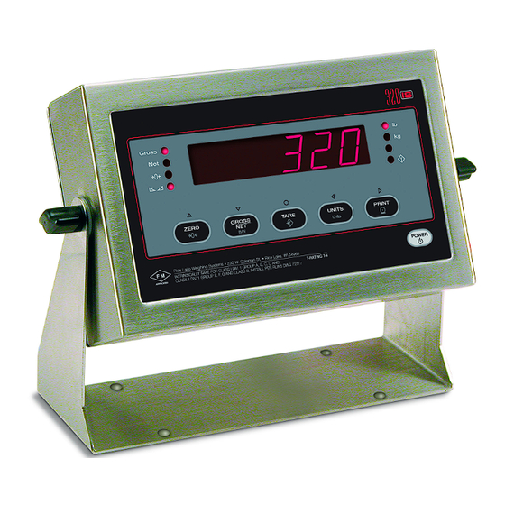
In setup mode, the keys are used to navigate through menus, select digits within numeric values, and increment/decrement values. See Section 3.2.3 on page 21 for information about using the front panel keys in setup mode. Gross Count Figure 1-1. 320IS Front Panel 320IS Installation Manual - Introduction... - Page 11 When moving through the menu parameters, the default or previously selected value appears first on the display. 320IS Installation Manual...
-
Page 12: Led Annunciators
The Tare Acquired light shows that a tare value has been entered. Count The Count annunciator is lit to show that the indicator is in piece count mode. Table 1-2. LED Annunciators 320IS Installation Manual - Introduction... -
Page 13: Indicator Operations
) annunciator is lit when a tare Tare value is currently stored in memory. 1.6.2 Toggle Units Press the key to switch between primary and secondary units. The appropriate units LED to the right of the UNITS display is lit. 320IS Installation Manual... -
Page 14: Zero Scale
DISPLAY TARE 1.6.8 Print Ticket Requires optional I/O Module (PN 72721). Wait for the standstill annunciator ( ). Press the key to send data to the serial port. Standstill must be lit PRINT to print. 320IS Installation Manual - Introduction... -
Page 15: Installation
If any parts are missing or were damaged in shipment, notify Rice Lake Weighing Systems and the shipper immediately. See Table 2-5 on page 19 for parts kit. -
Page 16: Hazardous Area Installation Of The 320Is
This will cause the power supply fuse to blow. The indicator should be powered by an FM-approved Rice Lake power supply or alternatively from an external battery pack. The power requirements of the... -
Page 17: Ac Power Wiring
Table 2-2. Estimated Battery Operating Times While connected to the DC battery pack with the indicator off, the 320IS still draws a small amount of current that will shorten battery run time. To preserve battery life, disconnect the battery when not in use. -
Page 18: Braided Power Cable Connection With Ferrite Core
4. Take the metal sleeve (from step 2) and insert it into the reducing gland taken from the parts kit. 5. Place the domed cap and reducing gland that were removed from the 320IS cord grip, into the parts kit (to be used as spares). -
Page 19: Braided Power Cable Connection Without Ferrite Core
4. Take the metal sleeve (from step 2) and insert it into the reducing gland taken from the parts kit. 5. Place the domed cap and reducing gland that were removed from the 320IS cord grip, into the parts kit (to be used as spares). -
Page 20: Foil Load Cell Cable Connection
7. Tighten until a small swelling of the rubber between the domed cap and the cable builds (see Figure 2-3). 8. Thread wires through ferrite core two times. Keep the ferrite as close to the backplate as possible (see Figure 2-4). 320IS Installation Manual - Installation... -
Page 21: Load Cells
J1 and J2 on. When connections are complete, reinstall connector CN3 on the board and use two cable ties to secure the load cell cable to the inside of the enclosure. Figure 2-6. CN3 Load Cell Connections 320IS Installation Manual... -
Page 22: Fiber Optics Installation
Torque screws to 15 in-lb (1.7 N-m). Torqued screws may become less tight as the gasket is compressed during torque pattern, therefore a Important second torque is required using the same pattern and torque value. 320IS Installation Manual - Installation... - Page 23 F i b e r o p t i c s c o r d g r i p Fillister head screws G r o u n d l u g Figure 2-8. 320IS Enclosure Backplate Figure 2-9. 320IS CPU Board Part Number Description (Quantity)
- Page 24 1/4 – 28NF x 1/4 Screw 44676 Bonded Sealing Washer, 1/4" 29635 SS Tilt Stand 68403 1/4 – 20 Two-Prong Black Knob 15144 1/4 x 1 x 1/16 Nylon Washer 100345 Reconditioned/Exchange 320IS Table 2-5. Hardware Replacement List 320IS Installation Manual - Installation...
-
Page 25: Control Drawings
Control Drawings 320IS Installation Manual... - Page 26 320IS Installation Manual - Installation...
-
Page 27: Configuration
EDP commands can be used to simulate pressing front panel keys, to configure the indicator, or to dump lists of parameter settings. See Section 5.0 on page 44 for more information about using the EDP command set. 320IS Installation Manual... -
Page 28: Front Panel Configuration
Configure analog output. See Section 3.3.7 on page 31 for analog output configuration. VERS Version Display installed software version number. Table 3-1. 320IS Menu Summary Menu Structures and Parameter Descriptions The following sections provide graphic representations of the menu structures. In the actual menu structure, 320IS the settings you choose under each parameter are arranged horizontally. -
Page 29: Configuration Menu
Zero track band — Automatically zeroes the scale when within the range specified, as long 0.5D as the input is within the configured zero range (ZRANGE parameter). Selections are ± display divisions. Maximum legal value varies depending on local regulations. Table 3-2. Configuration Menu Parameters 320IS Installation Manual... - Page 30 Tare function — Enables or disables push-button and keyed tares. Possible values are: NOTARE BOTH: Both push-button and keyed tares are enabled PBTARE NOTARE: No tare allowed (gross mode only) KEYED PBTARE: Push-button tares enabled KEYED: Keyed tare enabled Table 3-2. Configuration Menu Parameters (Continued) 320IS Installation Manual - Configuration...
-
Page 31: Format Menu
888880 primary unit display. Value should be consistent with local legal requirements. 888800 8.88888 88.8888 888.888 8888.88 88888.8 DSPDIV Display divisions. Selects the minimum division size for the primary units displayed weight. Table 3-3. Format Menu Parameters 320IS Installation Manual... -
Page 32: Calibration Menu
Press ENTER to remove an offset value from the zero and span calibrations. Use this parameter only after WZERO and WSPAN have been set. See Section 4.1 on page 33 for more information about using this parameter. Table 3-4. Calibration Menu Parameters 320IS Installation Manual - Configuration... -
Page 33: Serial Menu
EDP port. TERMIN EOLDLY ADDRES PORT ECHO PRINT BAUD Specifies the settings for baud rate, data bits, termination characters, and end-of-line delay used BITS by the printer port. TERMIN EOLDLY ADDRES PORT ECHO Table 3-5. Serial Menu Parameters 320IS Installation Manual... - Page 34 PORT RS232 Selects the physical interface for the EDP or printer port. RS422 RS485 CRLOOP NONE ECHO Enables or disables echoing of the serial commands sent to the indicator. Table 3-5. Serial Menu Parameters (Continued) 320IS Installation Manual - Configuration...
-
Page 35: Program Menu
Changing either CONSTU or CONSNU immediately resets the consecutive number used for printing. CONSTU 000000 Consecutive number start up value in the range of 000000–999999. Specifies the initial number consecutive number (CONSNU) value used when the indicator is powered on. Table 3-6. Program Menu Parameters 320IS Installation Manual... - Page 36 SLASH Specifies the date separator character. DASH SEMI TIMFMT 24HOUR Specifies the format used to display or print the time. 12HOUR TIMSEP COLON Specifies the time separator character. COMMA Table 3-6. Program Menu Parameters (Continued) 320IS Installation Manual - Configuration...
-
Page 37: Print Format Menu
FORMAT CALIBR SERIAL PROGRM PFORMT DIGIN ALGOUT VERS XXXXXXX XXXXXXX XXXXXXX DIGIN 1 - 4 CLRCN ZERO KBDLOC TARE HOLD NT/GRS CLRTAR CLRACC ACCUM GROSS UNITS ENTER NEWID PRIUNI SECUNI DSPTAR PRINT Figure 3-7. Digital Input Menu 320IS Installation Manual... -
Page 38: Analog Output Menu
TWZERO TWSPAN 000000 10000 65300 GROSS FULLSC HOLD number number number number ZEROSC ALOUT2 SOURCE OFFSET ERRACT TWZERO TWSPAN 000000 10000 65300 GROSS FULLSC HOLD number number number number ZEROSC Figure 3-8. Analog Output Menu 320IS Installation Manual - Configuration... -
Page 39: Version Menu
CONFIG FORMAT CALIBR SERIAL PROGRM PFORMT XXXXXXX XXXXXXX DIG IN XXXXXXX ALGOUT XXXXXXX VERS SOFTWR I/OMOD I/O Module Version Software Version Displays “No Ver” if no I/O Module is connected Figure 3-9. Version Menu 320IS Installation Manual... -
Page 40: Calibration
Calibration ® can be calibrated using the front panel, EDP commands, or the Revolution configuration utility. Each 320IS method consists of the following steps: • Zero calibration • Entering the test weight value • Span calibration • Optional re-zero calibration for test weights using hooks or chains. -
Page 41: Edp Command Calibration
EDP Command Calibration EDP command calibration requires the use of an I/O Module. To calibrate the indicator using EDP commands, the I/O Module EDP port must be connected to a terminal or personal computer. See Section 5.0 on page 44 for more information about using EDP commands. 1. - Page 42 3. Enter the to be used for span calibration then click Value of Test Weight 4. The Zero Calibration dialog box prompts you to remove all weight from the scale. Clear the scale and click to begin zero calibration. If your test weights require hooks or chains, place the hooks or chains on the scale for zero calibration. 5.
-
Page 43: Edp Commands
Scale must be at zero gross. 1. Type K1 and press ENTER RETURN 2. Type K5 and press ENTER 3. Type KTARE and press . The display shifts to net mode when the tare is entered. ENTER 320IS Installation Manual... - Page 44 Clears accumulated register KDISPTARE Display tare (pseudo key) Display unit ID entry screen KCOUNT Go to piece count mode (pseudo key) KCLR Press the clear key * I/O module required Table 5-1. EDP Key Press Commands 320IS Installation Manual - EDP Commands...
-
Page 45: Reporting Commands
Digital filter cutout threshold NONE, 2DD, 5DD, 10DD, 20DD, 50DD, 100DD, 200DD, 250DD TAREFN Tare function BOTH, NOTARE, PBTARE, KEYED SMPRAT Sample rate 15Hz, 30Hz, 60Hz, 7.5Hz NOTE: * X = 1, 2, 3 Table 5-3. CONFIG EDP Commands 320IS Installation Manual... - Page 46 EDP, PRN Table 5-6. SERIAL EDP Commands Command Description Values REGULAT Regulatory compliance NTEP, OIML, CANADA, NONE CONSNUM Consecutive number 0–999 999 CONSTUP Consecutive number start-up value 0–999 999 Table 5-7. PROGRM EDP Commands 320IS Installation Manual - EDP Commands...
- Page 47 AO1.OFFSET Zero offset 0%, 20% AO1.ERRACT Error action FULLSC, HOLD, ZEROSC AO1.MIN Minimum value tracked 0–999 990 AO1.MAX Maximum value tracked 0–999 990 AO1.TWZERO Zero calibration 0–65535 AO1.TWSPAN Span calibration 0–65535 Table 5-11. ALGOUT 1 EDP Commands 320IS Installation Manual...
-
Page 48: Normal Mode Commands
See Section 7.1.2 on page 46 for detailed information about the XE command response format. Transmit accumulation value set unit ID nnnnnn CONSNUM Set consecutive number Table 5-13. Normal Mode EDP Commands 320IS Installation Manual - EDP Commands... -
Page 49: Saving And Transferring Data
Calibration settings are included in the configuration data downloaded to the indicator. 320IS If the receiving indicator is a direct replacement for another and the attached scale is not changed, recalibration is not required. 1. ProComm Plus is a registered trademark of Symantec Corporation. 320IS Installation Manual... -
Page 50: Print Formatting
Format Default Format String Sample Output GFMT <G> GROSS<NL> 2046.81 LB GROSS NFMT <G> GROSS<NL> 4053.1 LB GROSS <T> TARE<NL> 15.6 LB TARE <N> NET<NL> 4037.5 LB NET Table 6-2. GFMT and NFMT Formats 320IS Installation Manual - Print Formatting... -
Page 51: Customizing Print Formats
Table 7-5 on page 49 and Table 7-7 on page 50) and are shown as blanks. The send or receive any ASCII character; the character printed depends on the particular ASCII character set implemented for the receiving device. 320IS Installation Manual... -
Page 52: Using Revolution
Using Revolution, you can type text directly into the grid, then select weight value fields from the tool bar and place them where you want them to appear on the printed ticket. Figure 6-2. Revolution Ticket Editor 320IS Installation Manual - Print Formatting... -
Page 53: Error Messages
Error Message Description Solution E A/D A/D physical error Call Rice Lake Weighing Systems (RLWS) Service. EEPERR EEPROM physical error EVIREE Virgin EEPROM Use TEST menu to perform DEFLT (restore defaults) procedure, then recalibrate load cells. -
Page 54: Status Messages
(see Table 7-3). If wwwwww uu more than one annunciator is lit, the second number returned is the sum of the values representing the active annunciators. 320IS Installation Manual - Appendix A... -
Page 55: Continuous Output (Stream) Format
O = Over/under range Weight data: 7 digits, right-justified, with decimal point, leading zero suppression. Overload = ^^^^^^^ Underrange = ] ] ] ] ] ] ] Display overflow = OVERFL Figure 7-1. Continuous Output Data Format 320IS Installation Manual... -
Page 56: Ascii Character Chart
Ctrl-I Ctrl-J Ctrl-K Ctrl-L Ctrl-M Ctrl-N Ctrl-O Ctrl-P Ctrl-Q Ctrl-R Ctrl-S Ctrl-T Ctrl-U Ctrl-V Ctrl-W Ctrl-X Ctrl-Y Ctrl-Z Ctrl-[ Ctrl-\ < Ctrl-] Ctrl-^ > Ctrl-_ Table 7-4. Table 7-5. ASCII Character Chart (Part 1) 320IS Installation Manual - Appendix A... - Page 57 Å » Ç É º æ ± Æ ³ ô £ ö ó ò õ û ¸ ù » ÿ ° · Ö Ü ¢ £ ¥ ƒ Table 7-6. Table 7-7. ASCII Character Chart (Part 2) 320IS Installation Manual...
-
Page 58: Conversion Factors For Secondary Units
8888.88, the indicator will overflow if 5 tons or more are applied to the scale. With 5 tons applied, and a conversion factor of 2000, the secondary units display needs five digits to the left of the decimal point to display the 10000 lb secondary units value. 320IS Installation Manual - Appendix A... - Page 59 0.001102 short tons 0.000984 long tons 0.001000 metric tons metric tons 2204.62 pounds 1000.00 kilograms 1.10231 short tons 0.984207 long tons long tons 2240.00 pounds 1016.05 kilograms 1.12000 short tons 1.01605 metric tons Table 7-8. Conversion Factors 320IS Installation Manual...
-
Page 60: Digital Filtering
DFSENS should be set higher to counter low frequency transients. Reconfigure as necessary to find the lowest effective value for the DFSENS parameter. 320IS Installation Manual - Appendix A... -
Page 61: Analog Output Calibration
5. Final zero calibration: Return to the TWZERO parameter and verify that the zero calibration has not drifted. Press and hold to re-adjust the zero value as required. Press to save the displayed Enter value. 6. Return to normal mode. Analog output function can be verified using test weights. 320IS Installation Manual... -
Page 62: Test Mode
D/O 3 D/O 4 A/O 1 A/O 2 DEFLT XMTEDP XMTPRN ECHO R Figure 7-4. Test Menu Exit Enter Move Left Move Right Not Used Figure 7-5. Front Panel Key Functions in Test Mode 320IS Installation Manual - Appendix A... - Page 63 Press and hold ENTER key to send ASCII “U” characters (decimal 85) from the serial port. ECHO R Echo received characters Press and hold ENTER key to view a string of characters terminated with a carriage return <CR> received at either serial port. Table 7-9. Test Menu Functions 320IS Installation Manual...
-
Page 64: Unpacking And Assembly
, Installation Manual (PN 78076), and a parts kit. If any parts were 320IS damaged in shipment, notify Rice Lake Weighing Systems and the shipper immediately. Enclosure Disassembly enclosure must be opened to connect cables for load cells, communications, and power. - Page 65 LIGHT PORT OPTICAL INPUT DGND IF-D91 OP10 PD 1 IF-E96 DGND ASSEMBL Y P/N LD 5 OPTICAL OUTPUT R4 3 LD 4 RICE LAKE WEIGHING SYSTEMS SO16 SOW16 RS-232/485 RS-232/485 20m A 20m A TVS4 Gnd- Gnd- DGND IGND DGND...
-
Page 66: Ac Wiring/Installation
(EDP and/or printer). EDP and printer ports should be configured separately. See Table 8-4 below for information on connecting RS-485. Description (Sign) Signal Ground (GND) — — — — — RS-485 line (A) RS-485 line (B) Table 8-4. RS-485 Connections (CN2 and CN3) 320IS Installation Manual - Appendix B... -
Page 67: Rs-422 Communications
The fiber optic connections between the indicator and the need to be cross-linked. The optical output 320IS of the indicator should be attached to the input of the , and the indicator’s input to the module’s output. 320IS Installation Manual... -
Page 68: Analog Outputs
Table 8-8 below. See Figure 8-1 on page 58 for the location of CN1 and DIP switches. Name Ground (Analog Output 1 Common) Analog Output 1 (current) Analog Output 1 (voltage) Analog Output 2 (current) Analog Output 2 (voltage) Ground (Analog Output 2 Common) Table 8-8. CN1 Connectors 320IS Installation Manual - Appendix B... -
Page 69: Digital Inputs
The states of the relay contacts are indicated by LEDs LD1–LD4 (see Figure 8-1 on page 58). When an LED is lit, the contacts of the corresponding relay are closed. See the applicable indicator installation manual for information on checking relay contact functionality. 320IS Installation Manual... - Page 70 Mounting surface must be capable of holding four times the weight of the and wiring. 1.75 7.50 4x Ø.25 10.84 (11.63) Ti ghten until clamps bottom out to fully compr ess gasket (12.90) Figure 8-5. 320IS Enclosure Dimensions 320IS Installation Manual - Appendix B...
- Page 71 Refer to I/O Module Installation Manual (PN 78076) for a complete parts list. .2 5 .6 3 Figure 8-6. I/O Module Assembly 320IS Installation Manual...
- Page 72 –25 to +70°C (-13 to +158°F) Humidity 0–95% relative humidity Enclosure Enclosure Dimensions 9.5 in x 6 in x 2.75 in 24 cm x 15 cm x 7 cm Weight 2.8 Kg (6.1 lb) 320IS Installation Manual - Appendix B...
- Page 73 Rating/Material UL Type 4X/IP-66 Certifications and Approvals FM #0Z0AZ.AX NTEP CoC Number 03-078 Accuracy ClassIII/III L : 10 000 File Number: E151461 320IS Installation Manual...
- Page 74 320IS Limited Warranty Rice Lake Weighing Systems (RLWS) warrants that all RLWS equipment and systems properly installed by a Distributor or Original Equipment Manufacturer (OEM) will operate per written specifications as confirmed by the Distributor/OEM and accepted by RLWS. All systems and components are warranted against defects in materials and workmanship for one year.
- Page 75 320IS Installation Manual...
- Page 77 230 W. Coleman St. • Rice Lake, WI 54868 • USA U.S. 800-472-6703 • Canada/Mexico 800-321-6703 • International 715-234-9171 • Europe +31 (0)26 472 1319 www.ricelake.com www.ricelake.mx www.ricelake.eu www.ricelake.co.in m.ricelake.com © Rice Lake Weighing Systems 06/2015 PN 76412 Rev C...
Need help?
Do you have a question about the 320IS and is the answer not in the manual?
Questions and answers