
Subscribe to Our Youtube Channel
Related Manuals for AJA HD10CEA


Summary of Contents for AJA HD10CEA
- Page 1 HD10CEA SDI/HD-SDI to Analog Audio/Video Converter Published: 1/5/11 Installation and Operation Guide B e c a u s e m a t t e r s .
-
Page 2: Contacting Support
AJA Video warrants that this product will be free from defects in materials and workmanship for a period of five years from the date of purchase. If a product proves to be defective during this warranty period, AJA Video, at its option, will either repair the defective product without charge for parts and labor, or will provide a replacement in exchange for the defective product. -
Page 3: Block Diagram
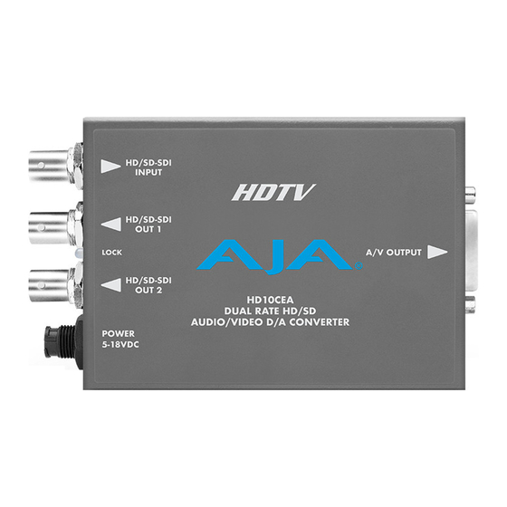
AJA HD10CEA SDI/HD-SDI to Analog Audio/Video Converter Introduction The HD10CEA converts SDI/HD-SDI video with embedded audio to analog video and 4 channel balanced analog audio. SD video outputs can be configured as YPbPr (Betacam or SMPTE/EBU-N10), RGB, composite or YC (S- Video). -
Page 4: User Controls
View HD10CEA Converter User Controls The user interface for the HD10CEA is an 8-switch DIP accessible through a cut-out in the bottom of the unit. Use the DIP switches to configure video outputs, pedestal, select audio channel groups, and set audio level. - Page 5 AJA HD10CEA SDI/HD-SDI to Analog Audio/Video Converter Note: The composite, S-video, component beta and pedestal switches (Switches 1 through 3) only function when the input is Standard Definition SDI. When supplied with HD-SDI, only component SMPTE or RGB video output is possible from the HD10CEA.
- Page 6 Switches 6 and 7—Select Audio Levels for Output Together these two switches select audio output levels at the XLR outputs. The following table shows the level selected by each switch position for the two DIP switches. Audio Level (dbu) +24.00 dBu (default) 0ff (Left) 0ff (Left) +18.00 dBu...
- Page 7 Typically, HD10CEA installation consists of the following steps: 1. Ensure the HD10CEA is disconnected from power. 2. Connect equipment to the convertor BNCs and cable snake BNCs/XLRs. 3. Apply +5-18VDC power to the converter (AJA power supply model DWP or DWP- Specifications Item Specification...
Need help?
Do you have a question about the HD10CEA and is the answer not in the manual?
Questions and answers