Vega VEGAPULS 69 Operating Instructions Manual
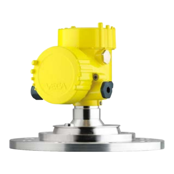
Radar sensor for continuous level
measurement of bulk solids.
4...20 ma/hart - four-wire
Hide thumbs
Also See for VEGAPULS 69:
- Operating instructions manual (104 pages) ,
- Quick setup manual (25 pages) ,
- Mounting instructions (24 pages)

Related Manuals for Vega VEGAPULS 69


Summary of Contents for Vega VEGAPULS 69
-
Page 1: Operating Instructions
Operating Instructions Radar sensor for continuous level measurement of bulk solids VEGAPULS 69 4 … 20 mA/HART - four-wire Document ID: 47249... - Page 2 Connect the PC ......................53 Parameter adjustment ....................54 Saving the parameter adjustment data ................55 Set up with other systems DD adjustment programs ....................56 Field Communicator 375, 475 ..................56 VEGAPULS 69 • 4 … 20 mA/HART - four-wire...
- Page 3 11.5 Trademark ........................85 Safety instructions for Ex areas Take note of the Ex specific safety instructions for Ex applications. These instructions are attached as documents to each instrument with Ex approval and are part of the operating instructions manual. Editing status: 2016-03-23 VEGAPULS 69 • 4 … 20 mA/HART - four-wire...
-
Page 4: Function
This arrow indicates a single action. Sequence of actions Numbers set in front indicate successive steps in a procedure. Battery disposal This symbol indicates special information about the disposal of bat- teries and accumulators. VEGAPULS 69 • 4 … 20 mA/HART - four-wire... -
Page 5: For Your Safety 2.1 Authorised Personnel
During work on and with the device the required personal protective equipment must always be worn. Appropriate use VEGAPULS 69 is a sensor for continuous level measurement. You can find detailed information about the area of application in chapter "Product description". Operational reliability is ensured only if the instrument is properly used according to the specifications in the operating instructions manual as well as possible supplementary instructions. -
Page 6: Ce Conformity
English language. This device complies with Part 15 of the FCC Rules. Operation is subject to the following two conditions: • This device may not cause interference, and VEGAPULS 69 • 4 … 20 mA/HART - four-wire... -
Page 7: Radio License For Canada
L'appareil ne doit pas produire de brouillage , et • L'utilisateur de l'appareil doit accepter tout brouillage radioélect- rique subi, même si le brouillage est susceptible d'en compromet- tre le fonctionnement VEGAPULS 69 • 4 … 20 mA/HART - four-wire... -
Page 8: Environmental Instructions
That is why we have introduced an environment management system with the goal of continuously improving company environmental pro- tection. The environment management system is certified according to DIN EN ISO 14001. Please help us fulfil this obligation by observing the environmental instructions in this manual: • Chapter "Packaging, transport and storage" • Chapter "Disposal" VEGAPULS 69 • 4 … 20 mA/HART - four-wire... -
Page 9: Configuration
Go to www.vega.com "VEGA Tools" and "Instrument search". Enter the serial number. Alternatively, you can access the data via your smartphone: • Download the smartphone app "VEGA Tools" from the "Apple App Store" or the "Google Play Store" VEGAPULS 69 • 4 … 20 mA/HART - four-wire... -
Page 10: Principle Of Operation
In this operating instructions manual, the optional instrument features are described. The respective scope of delivery results from the order specification. Principle of operation Application area The VEGAPULS 69 is a radar sensor for continuous level measure- ment of bulk solids even under the most difficult process conditions and in very large measuring ranges. It is ideal for use in high, slender silos with poorly reflecting bulk solids such as fly-ash, plastic granules or wood chips as well as internal installations that cause strong false echoes. -
Page 11: Packaging, Transport And Storage
The interface adapter VEGACONNECT enables the connection of communication-capable instruments to the USB interface of a PC. For parameter adjustment of these instruments, the adjustment software PACTware with VEGA-DTM is required. You can find further information in the operating instructions "Interface adapter VEGACONNECT" (Document-ID 32628). VEGAPULS 69 • 4 … 20 mA/HART - four-wire... - Page 12 3 Product description The VEGADIS 81 is an external display and adjustment unit for VEGA VEGADIS 81 plics sensors. ® For sensors with double chamber housing the interface adapter "DISADAPT" is also required for VEGADIS 81. You can find further information in the operating instructions "VE- GADIS 81" (Document-ID 43814).
- Page 13 The supplementary electronics is a replacement part for the following ics 4 … 20 mA/HART - sensors with 4 … 20 mA/HART - two-wire: four-wire • VEGAPULS series 60 • VEGAFLEX 80 series • VEGABAR series 80 You can find further information in the operating instructions "Supple- mentary electronics for 4 … 20 mA/HART - four-wire" (Document-ID 42766). VEGAPULS 69 • 4 … 20 mA/HART - four-wire...
-
Page 14: Mounting 4.1 General Instructions
The mounting position and orientation of the sensor must take into ac- Radio license for USA/ Canada count the limitations in chapter "For your safety", "Radio approval for USA" "Radio approval for Canada" of this operating instructions. VEGAPULS 69 • 4 … 20 mA/HART - four-wire... -
Page 15: Mounting Versions, Plastic Horn Antenna
This allows swivelling the sensor up to 180° for optimal orientation and rotating for optimal connection. Fig. 2: Ceiling mounting via the mounting strap with length 300 mm Fig. 3: Rotating with ceil mounting Mounting strap - Wall As an alternative the strap mounting is carried out horizontally or mounting obliquely. VEGAPULS 69 • 4 … 20 mA/HART - four-wire... - Page 16 • Combi compression flange fitting to DN 80 (ASME 3" and JIS 80) • Adapter flange from DN 100 (ASME 4" or JIS 100) The combi compression flange is suitable for different flange stand- ards and can be used for simple applications. It comes unassembled and not sealed against the radar sensor and can thus only be used unpressurized. It can be retrofitted on instruments with single cham- ber housing, retrofitting to a double chamber housing is not possible. VEGAPULS 69 • 4 … 20 mA/HART - four-wire...
-
Page 17: Mounting Preparations, Mounting Strap
The mounting strap is supplied unassembled (optionally) and must be screwed to the sensor before setup with three hexagon socket screws M5 x 10 and spring washers. Max. torque, see chapter "Technical data". Required tools: Allen wrench size 4. There are two different variants of screwing the strap to the sensor, see following illustration: VEGAPULS 69 • 4 … 20 mA/HART - four-wire... -
Page 18: Mounting Instructions
Nose for marking the direction of polarisation Information: When the housing is rotated, the direction of polarization changes and hence the influence of the false echo on the measured value. Please keep this in mind when mounting or making changes later. Installation position Mount the sensor at least 200 mm (7.874 in) away from the vessel wall. VEGAPULS 69 • 4 … 20 mA/HART - four-wire... - Page 19 Inflowing medium The instrument should not be mounted too close to the inflowing medium, as the radar signal could be disrupted. Silo with filling from top The optimal mounting position is opposite the filling aperture. To avoid heavy soiling, the distance to any filter or dust exhauster should be as large as possible. Fig. 11: Mounting of the radar sensor with inflowing medium Silo with lateral filling In bulk solids silos with lateral pneumatic filling the instrument should not be mounted above the filling stream, as the radar signal will be disrupted. The optimal mounting position is to the side of the filling aperture. To avoid heavy soiling, the distance to any filter or dust exhauster should be as large as possible. VEGAPULS 69 • 4 … 20 mA/HART - four-wire...
- Page 20 This reduces false echoes from the vessel mounting socket. Fig. 13: Recommended socket mounting If the medium has good reflective properties, you can also mount the VEGAPULS 69 on longer sockets. Approximate socket heights are shown in the following illustration. Information: When mounting on longer sockets, we recommend carrying out a false echo storage (see chapter "Parameter adjustment").
- Page 21 In a cylindrical silo with conical outlet, the sensor is mounted anywhere from one third to one half of the vessel radius from the outside wall (see following drawing). VEGAPULS 69 • 4 … 20 mA/HART - four-wire...
- Page 22 The necessary angle of inclination depends on the vessel dimensions. It can be easily checked with a suitable bubble tube or mechanic's level on the sensor. VEGAPULS 69 • 4 … 20 mA/HART - four-wire...
- Page 23 The following table shows the necessary angle of inclination. It depends on the measuring distance and the distance "a" between vessel centre and installation position. Distance d 2° 4° 6° 8° 10° 10.5 12.2 VEGAPULS 69 • 4 … 20 mA/HART - four-wire...
- Page 24 In case of existing vessel installations, a false echo storage should be carried out during setup. If large vessel installations such as struts or supports cause false echoes, these can be attenuated through supplementary measures. Small, inclined sheet metal baffles above the installations scatter the radar signals and prevent direct interfering reflections. VEGAPULS 69 • 4 … 20 mA/HART - four-wire...
- Page 25 Information: The spacer may only be incorporated up to a maximum of 50 mm into the vessel insulation. Only then is a reliable temperature decoupling guaranteed. VEGAPULS 69 • 4 … 20 mA/HART - four-wire...
- Page 26 The best mounting location is on the outer wall of the silo, with the sensor pointing towards the discharge opening in the silo centre. This can be accomplished, for example, with the mounting strap. Fig. 21: Installation and orientation in multiple chamber silos VEGAPULS 69 • 4 … 20 mA/HART - four-wire...
- Page 27 Fig. 23: Rinsing air connection on metal-jacketed lens antenna Plastic horn antenna The VEGAPULS 69 with plastic horn antenna is optionally available with a rinsing air connection. The mechanical configuration differs according to the flange version, see following graphics. VEGAPULS 69 • 4 … 20 mA/HART - four-wire...
- Page 28 4 Mounting Fig. 24: Rinsing air connection with compression flange Fig. 25: Rinsing air connection with adapter flange You can find details on the rinsing air connection in chapter "Technical data". VEGAPULS 69 • 4 … 20 mA/HART - four-wire...
-
Page 29: Connecting To Power Supply 5.1 Preparing The Connection
In the case of instrument housings with metric thread, the cable glands are screwed in at the factory. They are sealed with plastic plugs as transport protection. You have to remove these plugs before electrical connection. VEGAPULS 69 • 4 … 20 mA/HART - four-wire... -
Page 30: Connection
When reinserting the terminal block, you should hear it snap in. Connection procedure Proceed as follows: 1. Unscrew the housing lid 2. Loosen compression nut of the cable gland and remove blind plug VEGAPULS 69 • 4 … 20 mA/HART - four-wire... - Page 31 The terminal blocks are pluggable and can be removed from the housing insert. To do this, lift the terminal block with a small screwdriv- er and pull it out. When inserting the terminal block again, you should hear it snap in. VEGAPULS 69 • 4 … 20 mA/HART - four-wire...
-
Page 32: Wiring Plan, Double Chamber Housing
Voltage supply Voltage supply 4 … 20 mA output (active) 4 … 20 mA output (passive) Mass - output Function ground when in- stalling according to CSA (Canadian Standards Asso- ciation) VEGAPULS 69 • 4 … 20 mA/HART - four-wire... -
Page 33: Double Chamber Housing With Disadapt
CSA (Canadian Standards Asso- ciation) Double chamber housing with DISADAPT Electronics compartment Fig. 30: View to the electronics compartment with DISADAPT for connection of the external display and adjustment unit 1 DISADAPT Internal plug connection Plug connector M12 x 1 VEGAPULS 69 • 4 … 20 mA/HART - four-wire... -
Page 34: Switch-On Phase
As soon as a plausible measured value is found, the corresponding current is outputted to the signal cable. The value corresponds to the actual level as well as the settings already carried out, e.g. factory setting. VEGAPULS 69 • 4 … 20 mA/HART - four-wire... -
Page 35: Set Up With The Display And Adjustment Module 6.1 Insert Display And Adjustment Module
Fig. 32: Installing the display and adjustment module in the double chamber housing Note: If you intend to retrofit the instrument with a display and adjustment module for continuous measured value indication, a higher lid with an inspection glass is required. VEGAPULS 69 • 4 … 20 mA/HART - four-wire... -
Page 36: Adjustment System
1 s, the cursor moves continuously. When the [OK] and [ESC] keys are pressed simultaneously for more than 5 s, the display returns to the main menu. The menu language is then switched over to "English". VEGAPULS 69 • 4 … 20 mA/HART - four-wire... -
Page 37: Measured Value Indication - Selection National Language
The echo curve of setup is stored automatically during the quick setup. The return to the measured value indication is carried out through the [->] or [ESC] keys or automatically after 3 s You can find "Extended adjustment" in the next sub-chapter. VEGAPULS 69 • 4 … 20 mA/HART - four-wire... -
Page 38: Parameter Adjustment - Extended Adjustment
With this menu item, the sensor can be optimally adapted to the ap- plication, the installation location or the measurement conditions. It includes selection options for medium, application as well as vessel height/measuring range. VEGAPULS 69 • 4 … 20 mA/HART - four-wire... - Page 39 Vessel height/Measuring range: The VEGAPULS 69 is a bulk solids radar sensor for high, slender vessels. It covers a measuring range up to 120 m. This menu item lets you limit the active measuring range in which the instrument searches for level echoes.
- Page 40 – Max. reaction speed, very high measured value jumps are accepted The instrument recognizes if a manual false signal suppression was carried out with empty vessel and high system noise. An automatic false signal sup- pression is then carried out if a product echo was detected at the beginning of the filling process. VEGAPULS 69 • 4 … 20 mA/HART - four-wire...
- Page 41 The actual product level during this adjustment is not important, because the min./max. adjustment is always carried out without changing the product level. These settings can be made ahead of time without the instrument having to be installed. VEGAPULS 69 • 4 … 20 mA/HART - four-wire...
- Page 42 The cursor jumps now to the distance value. 4. Enter the suitable distance value in m for the empty vessel (e.g. distance from the sensor to the vessel bottom) corresponding to the percentage value. VEGAPULS 69 • 4 … 20 mA/HART - four-wire...
- Page 43 With active PIN, adjustment via PACTware/DTM as well as other systems is also blocked. Display - Menu language This menu item enables the setting of the requested national lan- guage. The following languages are available: VEGAPULS 69 • 4 … 20 mA/HART - four-wire...
- Page 44 • Polish • Czech • Turkish In the delivery status, the VEGAPULS 69 is set to the ordered national language. Display - Displayed value In this menu item you can define the way measured values are indi- 1 and 2 cated on the display. The default setting for the display value is "Percent".
- Page 45 [OK] key. Information: The sensor terminates the simulation automatically after 60 minutes. Diagnostics - Echo curve The function "Setup" allows the echo curve to be saved at the time of memory setup. VEGAPULS 69 • 4 … 20 mA/HART - four-wire...
- Page 46 1. Select with [->] under "Additional adjustments" the menu item "Reset" and confirm with [OK]. 2. Confirm with [OK] and select the requested reset function with [->] 3. Confirm with [OK], for approx. 5 s the message "Resetting" is displayed, then the selection window appears. VEGAPULS 69 • 4 … 20 mA/HART - four-wire...
- Page 47 Output characteristics: 4 … 20 mA mode Failure mode: < 3.6 mA ▼ Current output Min. current: 3.8 mA Min./Max. Max. current: 20.5 mA Display Displayed value 1 Filling height Displayed value 2 Temperature Backlight Switched off VEGAPULS 69 • 4 … 20 mA/HART - four-wire...
- Page 48 Additional settings - Scal- In the menu item "Scaling" you define the scaling variable and the scaling format for the indication of the level measured value for 0 % and 100 % on the display, for example as volume in l. VEGAPULS 69 • 4 … 20 mA/HART - four-wire...
- Page 49 This should be done with a low level so that all potential interfering reflections can be detected. Proceed as follows: 1. Select with [->] the menu item "False signal suppression" and confirm with [OK]. 2. Confirm again with [OK]. VEGAPULS 69 • 4 … 20 mA/HART - four-wire...
- Page 50 The linearization applies to the measured value indication and the current output. Additional adjustments - In this menu item you specify the HART mode and enter the address HART mode for multidrop mode. VEGAPULS 69 • 4 … 20 mA/HART - four-wire...
- Page 51 In this menu item, the date of factory calibration of the sensor as well date as the date of the last change of sensor parameters are displayed via the display and adjustment module or via the PC. VEGAPULS 69 • 4 … 20 mA/HART - four-wire...
-
Page 52: Saving The Parameter Adjustment Data
If it is necessary to exchange a sensor, the display and adjustment module is inserted into the replacement instrument and the data are likewise written into the sensor via the menu item "Copy sensor data". VEGAPULS 69 • 4 … 20 mA/HART - four-wire... -
Page 53: Setup With Pactware 7.1 Connect The Pc
Connection via HART Fig. 36: Connecting the PC via HART to the signal cable 1 VEGAPULS 69 Voltage supply 4 … 20 mA signal output 4 HART resistance approx. 250 Ω (optional depending on processing) Connection cable with 2 mm pins and terminals 6 VEGACONNECT Processing system/PLC Necessary components: • VEGAPULS 69 VEGAPULS 69 • 4 … 20 mA/HART - four-wire... -
Page 54: Parameter Adjustment
Further setup steps are described in the operating instructions manu- al "DTM Collection/PACTware" attached to each DTM Collection and which can also be downloaded from the Internet. Detailed descrip- tions are available in the online help of PACTware and the DTMs. VEGAPULS 69 • 4 … 20 mA/HART - four-wire... -
Page 55: Saving The Parameter Adjustment Data
CD from the agency serving you. Saving the parameter adjustment data We recommend documenting or saving the parameter adjustment data via PACTware. That way the data are available for multiple use or service purposes. VEGAPULS 69 • 4 … 20 mA/HART - four-wire... -
Page 56: Set Up With Other Systems 8.1 Dd Adjustment Programs
This software is updated via the Internet and new EDDs are automatically taken over into the device catalogue of this software after they are released by the manufacturer. They can then be transferred to a Field Communicator. VEGAPULS 69 • 4 … 20 mA/HART - four-wire... -
Page 57: Maintenance
Echo curve of the setup: This is used as reference echo curve for the measurement conditions during setup. Changes in the measure- ment conditions during operation or buildup on the sensor can thus be recognized. The echo curve of the setup is stored via: VEGAPULS 69 • 4 … 20 mA/HART - four-wire... -
Page 58: Asset Management Function
PACTware/DTM or EDD. Out of specification: The measured value is unstable because the instrument specification is exceeded (e.g. electronics temperature). This status message is inactive by default. It can be activated by the user via PACTware/DTM or EDD. Maintenance: Due to external influences, the instrument function is limited. The measurement is affected, but the measured value is VEGAPULS 69 • 4 … 20 mA/HART - four-wire... - Page 59 – EMC interference – Remove EMC influences Bit 12 of Byte 0…5 – Transmission error with – Exchange 4-wire power Communication error the external communica- supply unit or electron- tion with 4-wire power supply unit VEGAPULS 69 • 4 … 20 mA/HART - four-wire...
- Page 60 – Temperature of the – Check ambient tem- Bit 8 of Byte 14…24 electronics in the non- perature Impermissible electronics specified range – Isolate electronics temperature – Use instrument with higher temperature range VEGAPULS 69 • 4 … 20 mA/HART - four-wire...
- Page 61 – Remove possible false tive echoes – Optimize sensor position and orientation M506 – Error during setup – Check or correct instal- Bit 6 of Byte 14…24 lation and/or parameter Installation/Setup error adjustment VEGAPULS 69 • 4 … 20 mA/HART - four-wire...
-
Page 62: Rectify Faults
• Constant level • Filling • Emptying The images in column "Error pattern" show the real level as a broken line and the level displayed by the sensor as a continuous line. VEGAPULS 69 • 4 … 20 mA/HART - four-wire... - Page 63 – Determine the reason for the signal has changed (e.g. con- changed false signals, carry out densation, buildup); false signal false signal suppression, e.g. suppression no longer matches with condensation actual conditions VEGAPULS 69 • 4 … 20 mA/HART - four-wire...
- Page 64 – Minimize interfering instal- lations in the close range by changing the polarization direction – After eliminating the false sig- nals, the false signal suppres- sion must be deleted. Carry out a new false signal suppression VEGAPULS 69 • 4 … 20 mA/HART - four-wire...
-
Page 65: Exchanging The Electronics Module
24 hour service hotline Should these measures not be successful, please call in urgent cases the VEGA service hotline under the phone no. +49 1805 858550. The hotline is also available outside normal working hours, seven days a week around the clock. -
Page 66: Software Update
Attach the completed form and, if need be, also a safety data sheet outside on the packaging • Please contact the agency serving you to get the address for the return shipment. You can find the agency on our home page www.vega.com. VEGAPULS 69 • 4 … 20 mA/HART - four-wire... -
Page 67: Dismounting Steps
Pass the instrument directly on to a spe- cialised recycling company and do not use the municipal collecting points. These may be used only for privately used products according to the WEEE directive. VEGAPULS 69 • 4 … 20 mA/HART - four-wire... -
Page 68: Technical Data
Ʋ Instrument (depending on housing, approx. 2 … 17.2 kg (4.409 … 37.92 lbs) process fitting and antenna) Torques Max. torques, threaded version Ʋ G¾ 30 Nm (22.13 lbf ft) Ʋ G1½ 200 Nm (147.5 lbf ft) VEGAPULS 69 • 4 … 20 mA/HART - four-wire... - Page 69 Shortcircuit protection Available Potential separation Available Signal resolution 0.3 µA Failure signal current output (adjustable) mA-value unchanged 20.5 mA, 22 mA, < 3.6 mA Max. output current 22 mA Starting current ≤ 3.6 mA VEGAPULS 69 • 4 … 20 mA/HART - four-wire...
- Page 70 Fig. 49: Deviation under reference conditions Reference plane Recommended min. distance Measuring range end Repeatability ≤ ±1 mm Deviation with bulk solids The values depend to a great extent on the application. Binding specifications are thus not possible. VEGAPULS 69 • 4 … 20 mA/HART - four-wire...
-
Page 71: Ambient Conditions
-40 … +80 °C (-40 … +176 °F) Time span (after a sudden measuring distance change of max. 2 m in bulk solids applications) until the output signal has taken on 90 % of the final value for the first time (IEC 61298-2). Outside the specified beam angle, the energy level of the radar signal is 50% (-3 dB) less. EIRP: Equivalent Isotropic Radiated Power. VEGAPULS 69 • 4 … 20 mA/HART - four-wire... - Page 72 Fig. 51: Ambient temperature - Process temperature, metal-jacketed lens antenna up to +130 °C (266 °F) Ambient temperature Process temperature Aluminium housing Plastic housing Stainless steel housing, precision casting Stainless steel housing, electropolished VEGAPULS 69 • 4 … 20 mA/HART - four-wire...
- Page 73 Shock resistance 100 g, 6 ms according to EN 60068-2-27 (mechanical shock) Data on rinsing air connection Max. permissible pressure 6 bar (87.02 psig) Air volume, depending on pressure (recommended range) VEGAPULS 69 • 4 … 20 mA/HART - four-wire...
- Page 74 Ʋ For connection G⅛ Ʋ Opening pressure 0.5 bar (7.25 psig) Ʋ Nominal pressure stage PN 250 Electromechanical data - version IP 66/IP 67 Cable gland M20 x 1.5 or ½ NPT VEGAPULS 69 • 4 … 20 mA/HART - four-wire...
- Page 75 Via the current output Ʋ Digital Via the digital output signal - depending on the electron- ics version Range -40 … +85 °C (-40 … +185 °F) Resolution < 0.1 K Accuracy ±3 K VEGAPULS 69 • 4 … 20 mA/HART - four-wire...
-
Page 76: Radio Astronomy Stations
"Instrument search" as well as in the download area. 11.2 Radio astronomy stations Certain restrictions on the use of VEGAPULS 69 outside closed vessels result from the radio license. You can find these restrictions in chapter "Radio license for Europe". Some of these restric- tions have to do radio astronomy stations. The following table states the geographic positions of... - Page 77 Plastic housing Aluminium/Stainless steel housing VEGAPULS 69, plastic horn antenna with compression flange ø 107 mm ø 21 mm (4.21") (0.83") ø 75 mm (2.95") ø 115 mm (4.53") ø 156 mm (6.14") ø 200 mm (7.87") Fig. 54: Radar sensor with compression flange Compression flange VEGAPULS 69 • 4 … 20 mA/HART - four-wire...
- Page 78 11 Supplement VEGAPULS 69, plastic horn antenna with compression flange and rinsing connection ø 107 mm ø 21 mm (4.21") (0.83") ø 75 mm (2.95") ø 156 mm (6.14") ø 200 mm (7.87") Fig. 55: Radar sensor with compression flange and rinsing connection Compression flange Reflux valve Rinsing connection VEGAPULS 69 • 4 … 20 mA/HART - four-wire...
- Page 79 11 Supplement VEGAPULS 69, plastic horn antenna with adapter flange ø 75 mm (2.95") ø 98 mm (3.86") Fig. 56: Radar sensor with adapter flange VEGAPULS 69 • 4 … 20 mA/HART - four-wire...
- Page 80 11 Supplement VEGAPULS 69, plastic horn antenna mit adapter flange und rinsing connection ø 75 mm (2.95") ø 98 mm (3.86") Fig. 57: VEGAPULS 69, adapter flange and air flushing ring Air flushing ring Reflux valve Adapter flange VEGAPULS 69 • 4 … 20 mA/HART - four-wire...
- Page 81 VEGAPULS 69, plastic horn antenna with mounting strap 125 mm (4.92") 2,5 mm (0.10") ø 75 mm (2.95") ø 107 mm (4.21") 9 mm (0.35") ø 115 mm (4.53") 12 mm (0.47") Fig. 58: VEGAPULS 69, plastic antenna and mounting strap in 170 or 300 mm length VEGAPULS 69 • 4 … 20 mA/HART - four-wire...
- Page 82 (1.69") 35 mm (1.38") 43 mm (1.69") 35 mm (1.38") Fig. 60: VEGAPULS 69, metal-jacketed lens antenna in flange version with rinsing connection Version up to 130 °C (266 °F) Version up to 200 °C (392 °F) Blind plug 90° angle joint Reflux valve VEGAPULS 69 • 4 … 20 mA/HART - four-wire...
- Page 83 11 Supplement VEGAPULS 69, metal-jacketed lens antenna with swivelling holder Fig. 61: VEGAPULS 69, metal-jacketed lens antenna and swivelling holder Version up to 130 °C (266 °F) Version up to 200 °C (392 °F) VEGAPULS 69 • 4 … 20 mA/HART - four-wire...
- Page 84 11 Supplement VEGAPULS 69, metal-jacketed lens antenna with swivelling holder and rinsing connection Fig. 62: VEGAPULS 69, metal-jacketed lens antenna with swivelling holder and rinsing connection Version up to 130 °C (266 °F) Version up to 200 °C (392 °F) Blind plug 90° angle joint Reflux valve VEGAPULS 69 • 4 … 20 mA/HART - four-wire...
-
Page 85: Industrial Property Rights
Les lignes de produits VEGA sont globalement protégées par des droits de propriété intellec- tuelle. Pour plus d'informations, on pourra se référer au site www.vega.com. VEGA lineas de productos están protegidas por los derechos en el campo de la propiedad indus- trial. Para mayor información revise la pagina web www.vega.com. - Page 86 Terminal compartment – Double chamber housing 32, 33 Functional principle 10 Type label 9 Grounding 30 Vessel installations 24 Vessel insulation 25 HART Voltage supply 29, 76 – Address 50 Linearization 50 VEGAPULS 69 • 4 … 20 mA/HART - four-wire...
- Page 87 Notes VEGAPULS 69 • 4 … 20 mA/HART - four-wire...
- Page 88 All statements concerning scope of delivery, application, practical use and operat- ing conditions of the sensors and processing systems correspond to the information available at the time of printing. Subject to change without prior notice © VEGA Grieshaber KG, Schiltach/Germany 2016...
Need help?
Do you have a question about the VEGAPULS 69 and is the answer not in the manual?
Questions and answers