Trane TR200 Operating Instructions Manual
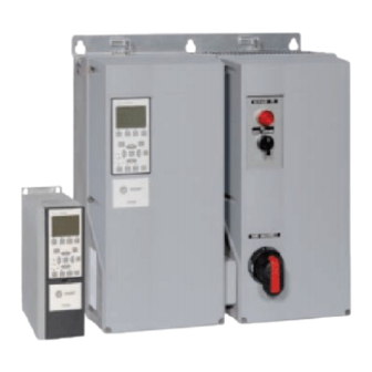
Option panel
Hide thumbs
Also See for TR200:
- Programming manual (297 pages) ,
- Instruction manual (205 pages) ,
- Operator's manual (86 pages)
Table of Contents
Advertisement
Table of Contents
Introduction
Purpose of the manual
Overview
Typical bypass operation
Bypass Circuits
Bypass Options
Bypass Platform Configurations
Switch Mode Power Supply (SMPS)
Disconnects
Main disconnect
Drive disconnect (optional)
Bypass selector switch
Option Panel Configurations
Option Panel Voltage and Frame Ratings
Pre-Installation
Receiving Inspection
Pre-installation Check
Installation Site Check
Harsh Environments
Airborne Liquids
Airborne Solids
Corrosive Chemicals
Installation
Tools Required
Branch Cuitcut Protection
Drive Fuses
Internal Option Panel Fuses
Mechanical Installation
TR200 Option Panel Operating Instructions
4
4
4
5
5
6
6
7
7
7
8
8
9
9
11
11
11
12
12
12
12
12
13
13
13
13
13
14
1
Advertisement
Table of Contents

Related Manuals for Trane TR200


Summary of Contents for Trane TR200
- Page 1 Option Panel Voltage and Frame Ratings Pre-Installation Receiving Inspection Pre-installation Check Installation Site Check Harsh Environments Airborne Liquids Airborne Solids Corrosive Chemicals Installation Tools Required Branch Cuitcut Protection Drive Fuses Internal Option Panel Fuses Mechanical Installation TR200 Option Panel Operating Instructions...
- Page 2 Inspection Prior to Start Up Start Up Procedure Electromechanical Bypass (EMB) Operation EMB(0) and EMB1 EMB Auto bypass EMB Common Run/Stop EMB Run Permissive EMB Overload EMB Safety Interlock EMB Fire Mode EMB Fault Reporting TR200 Option Panel Operating Instructions...
- Page 3 ECB Overload ECB Safety Interlock ECB Common Run/Stop ECB Advanced Fire Mode ECB Fault Reporting Non-bypass Component Functions Power Fusing Reactors Disconnects Motor Options Contactor Motor Select Start Up Troublehooting Option Panel Alarm and Warnings TR200 Option Panel Operating Instructions...
-
Page 4: Introduction
This manual is intended to provide detailed information for the installation and operation of the option panel used in conjunction with a Trane variable frequency drive (VFD or drive). To enable efficient handling of the equipment, requirements are provided for installation of mechanical, electrical, and control wiring, proper grounding, and environmental considerations. -
Page 5: Typical Bypass Operation
Display data indicates when in bypass. The circuitry may be supplied with either an input dis- connect switch or an input circuit breaker. Contactor Drive Mode Bypass Mode Test Mode Closed Open Open Closed Closed Open Open Open Open Open Closed Closed Table 1.2 Illustration 1.1: Basic 3-contactor Bypass Functions TR200 Option Panel Operating Instructions... -
Page 6: Bypass Options
The EMB is available in three platforms: EMB(0), EMB1, and EMB2. The features available as options with each platform are listed in the following table. The ECB, also listed below, has all option features available. See Chapter 5 for additional details on the EMB and Chapter 6 for the ECB. TR200 Option Panel Operating Instructions... -
Page 7: Switch Mode Power Supply (Smps)
When in the ON position, a trip fault removes power from the drive/bypass circuit and the switch moves to the TRIP setting. It must be moved to the RESET position momentarily after the fault has been cleared to reset the circuit breaker. TR200 Option Panel Operating Instructions... -
Page 8: Drive Disconnect (Optional)
Twoposition (ON/OFF) rotary switch disconnects main AC line input power to the drive only. Bypass selector switch The bypass selector switch is used for either the 2- contactor or 3-contactor bypass for EMB units. Illustration 1.3: Disconnects Bypass selector switch Main disconnect Drive disconnect TR200 Option Panel Operating Instructions... -
Page 9: Option Panel Configurations
460-480 15-25 208-230 40-60 575-600 15-25 460-480 100-125 575-600 100-125 Table 1.6 Table 1.9 Frame B2 Volts VAC Frame D1 208-230 Volts VAC 460-480 30-40 460-480 150-200 575-600 30-40 575-600 150-200 Table 1.7 Table 1.10 TR200 Option Panel Operating Instructions... - Page 10 Introduction Frame D2 Volts VAC 460-480 250-350 575-600 250-400 Table 1.11 TR200 Option Panel Operating Instructions...
-
Page 11: Pre-Installation
If you give the transportation company a clear receipt for equipment that has been damaged or lost in transit, you do so at your own risk and expense. Trane IS WILLING TO ASSIST YOU TO COLLECT CLAIMS FOR LOSS OR DAMAGE, BUT WILLINGNESS ON OUR PART DOES NOT MAKE US RESPONSIBLE FOR COLLECTION OF CLAIMS OR REPLACEMENT OF MATERIAL. -
Page 12: Installation Site Check
A non-ventilated cabinet fitted with an air conditioner as a heat exchanger may be used. Conformal coated circuit boards may be specified to reduce the corrosive effects of a harsh environment. TR200 Option Panel Operating Instructions... -
Page 13: Installation
When applicable, use the specified fuse or an equivalent replacement only for internal option panel fuses. Fuse options include the drive disconnect and contactor fuses. See the nameplate label (table below) on the inside cover of the unit for option panel fuse ratings. TR200 Option Panel Operating Instructions... -
Page 14: Mechanical Installation
Lift unit slightly using lifting rings with weight distributed evenly. • Remove skid and other supports from under drive. • For floor mounting applications, a floor mounting kit is available from Trane specifically designed to anchor drive to floor. Forklift •... -
Page 15: Shipping Weights
No additional back plate is required for drives with the option panel. • Units may be mounted flush to the wall or free standing. A free-standing mounting kit is available from Trane. • See table below for temperature ratings. TR200 Option Panel Operating Instructions... - Page 16 45° C 40° C C2, D1-D2 40° C 40° C Table 3.4 Illustration 3.3: Side Cooling Clearance, A-2 and A-3 Frames CEILING AIRFLOW 4.0 in min. 4.0 in min. AIRFLOW FLOOR Illustration 3.4: Cooling Airflow TR200 Option Panel Operating Instructions...
-
Page 17: Electrical Installation
Power from the option enclosure to the motor (and earth ground) • Control wiring Control wiring should always be isolated from the high voltage power wiring. Avoid getting metal chips into electronics. Follow the connection procedures as illustrated in the drawing provided with the unit. TR200 Option Panel Operating Instructions... -
Page 18: Component Identification
The below figure represents a typical layout drawing. The following table provides definitions for drawing reference designators. (Not all reference designators are shown.) Illustration 3.6: Sample Mechanical Layout Diagram TR200 Option Panel Operating Instructions... -
Page 19: Wire And Cable Access
Removable access covers are provided for cable connections (see figure ). Re- move access covers prior to drilling holes to prevent metal shavings from damaging internal electronic components. • For some units, access holes are provided for input power, motor leads, and control wiring. TR200 Option Panel Operating Instructions... -
Page 20: Wire Size
Terminal Tightening Torques • Tighten all connections to the torque specifications provided. • The torque tightening specifications are located on the tightening torque and wire rating label inside the cover of the option panel (see figure below.) TR200 Option Panel Operating Instructions... -
Page 21: Input Line Connection
Motor wiring should always be as short as practical. Grounding (Earthing) WARNING GROUNDING HAZARD! FOR OPERATOR SAFETY, IT IS IMPORTANT TO GROUND OPTION PANEL PROPERLY. FAILURE TO GROUND OPTION PANEL PROPERLY COULD RESULT IN DEATH OR SERIOUS INJURY. TR200 Option Panel Operating Instructions... -
Page 22: Control Wiring
It is recommended that control wiring is rated for 600 V for 480 V and 600 V drives and 300 V for 200-240 V drives. • Isolate control wiring from high power components in the drive. • See label inside of panel cover for details. Illustration 3.7: Control Terminals Location EIA-485 terminal Jumper wire TR200 Option Panel Operating Instructions... -
Page 23: Serial Communication Bus Connection
If shielded cabling is used, do not connect end of shield to terminal 61. Programming Serial communication point maps, parameter settings, and other details for bypass option functionality are included in the serial communication materials supplied with the unit. TR200 Option Panel Operating Instructions... -
Page 24: Start Up
Check that overload relay(s) is set for FLA of connected motor. Service factor is built into overload relay. For drive start up procedures, see drive instruction manual. Inspection Prior to Start Up Before applying power to the unit, inspect the entire installation as detailed in table below. TR200 Option Panel Operating Instructions... -
Page 25: Start Up Procedure
Ensure that all operator devices are in OFF position. Main and drive disconnect switches on front of elec- tromechanical bypass panel must be in OFF position. Panel door(s) closed. Keep main disconnect switch in OFF position and apply voltage to option panel. DO NOT operate drive or bypass at this time. TR200 Option Panel Operating Instructions... - Page 26 Check full load amps on input terminals L1, L2, and L3. Verify that current is within FLA of drive and balanced within 3%. If incorrect, see Troubleshooting Section in this manual for isolation procedures. 10. Check full load amps in bypass mode on motor terminals. TR200 Option Panel Operating Instructions...
- Page 27 12. Exercise safety circuit and verify that unit stops running. 13. Exercise start/stop circuit and verify that unit starts and stops with system in auto mode of operation. TR200 Option Panel Operating Instructions...
-
Page 28: Electromechanical Bypass (Emb) Operation
Electromechanical Bypass (EMB) Operation Illustration 5.1: Customer-side EMB2 Control Card Terminal Connctions TR200 Option Panel Operating Instructions... - Page 29 The second of the following tables lists common functions for controlling a motor(s) with a bypass and the typical terminal connections used. Commands enable drive functions. Status reports describe conditions but do not enable a function. TR200 Option Panel Operating Instructions...
- Page 30 External Inter- lock Term 27 Mode Input External Inter- lock Term 27 digital External Interlock External Inter- input lock Term 29 Mode Output Auto bypass Term 29 digital No Alarm Auto bypass output Table 5.2 TR200 Option Panel Operating Instructions...
-
Page 31: Emb(0) And Emb1
If the drive is reinitialized, be sure that these settings are maintained or reset for proper bypass operation. See the mechanical layout diagram inside the cover of the unit for connector locations within the unit. TR200 Option Panel Operating Instructions... - Page 32 Mode Output Input Normally open, dry contact CMS Motor 1, close to select CMS Common Normally open, dry contact CMS common Input Normally open, dry contact CMS Motor 2, close to select Table 5.4 TR200 Option Panel Operating Instructions...
- Page 33 Parameter name Value number Value name Function Term 18 digital in- Start Common run/stop Digital I/O Mode External Interlock Term 27 Mode Input External Interlock Term 27 digital in- External Inter- External Interlock lock Table 5.6 TR200 Option Panel Operating Instructions...
-
Page 34: Emb Auto Bypass
Common run/stop is enabled by factory default. When used with the run permissive function, common run/stop permits run request operation in bypass. TR200 Option Panel Operating Instructions... -
Page 35: Emb Run Permissive
Wire the input run permission to connector X55, terminals 1 and 2 per the system application. Disable Run Permissive • Run permissive is enabled by factory default when ordered. • To disable the run permissive function, jumper between terminals 1 and 2 on connector X55. TR200 Option Panel Operating Instructions... -
Page 36: Emb Overload
It is highly recommended to operate in the manual factory setting to prevent the risk of damage to the motor. TRIP MANUAL AUTO TEST RESET 98NO 95NC 97NO 96NC Illustration 5.5: Sample Overload Device TR200 Option Panel Operating Instructions... -
Page 37: Emb Safety Interlock
The fault contacts are fail-safe, meaning that if power is removed a fault condition is automatically reported. Fault status is not monitored in bypass operation. TR200 Option Panel Operating Instructions... -
Page 38: Emb Switches
(M1 and M2 contactors), connected to the full-speed bypass (M3 contactor), or disconnected from both. The test position allows for operation in bypass while still providing power to the drive (M1 and M3). See figure below. Illustration 5.6: Basic 3-contactor Bypass Functions TR200 Option Panel Operating Instructions... -
Page 39: Electronically Controlled Bypass (Ecb) Operation
Terminal functions are programmed in the 5-00 parameter group. (See table below for factory default parameter settings for drives with an ECB.) Bypass functions are programmed in the 31-00 pa- rameter group (see later this chapter). See the drive’s supporting materials for detailed programming instruc- tions. TR200 Option Panel Operating Instructions... -
Page 40: Drive Control Terminals
Trane website. • Also provided are two Form C relay outputs that are in various locations depending upon the drive configuration and size. See the drive support materials for detailed instructions. Illustration 6.2: Drive Control Terminals TR200 Option Panel Operating Instructions... - Page 41 68 (+), 69 (-) RS-485 interface. When the drive is connected to an RS-485 serial communication bus, a drive control card switch is provided for termination resistance. ON for termination and OFF for no termination. See drive support materials for details. Table 6.2 TR200 Option Panel Operating Instructions...
-
Page 42: Ecb Control Card
X59 for reporting the bypass mode of operation, either drive mode or running in bypass. See the next table for ECB control card terminal types and functions. Illustration 6.3 Terminal X58 Terminal X56 Terminal X57 Terminal X59 TR200 Option Panel Operating Instructions... - Page 43 Electronically Controlled Bypass (ECB) Oper- ation Illustration 6.4: ECB Control Card Terminal Connections TR200 Option Panel Operating Instructions...
- Page 44 Common for binary I/O Relay Output Term. Function N.O. contact for running in bypass or drive Relay output for user N.O. contact for running in bypass or drive Relay output for user 3-12 Factory use only Table 6.3 TR200 Option Panel Operating Instructions...
-
Page 45: Ecb Drive Or Bypass Selection
CANCEL to remain in by- pass mode. 4. Press STATUS key to return to drive status display. Table 6.4 NOTE PRESSING THE INFO KEY AT ANY TIME DISPLAYS TIPS AND GUIDELINES FOR PERFORMING THE FUNCTION CURRENTLY ACTIVATED. Illustration 6.5 TR200 Option Panel Operating Instructions... -
Page 46: Ecb Programming
0-9. Selected digit is inverse highlighted. 9. Press OK key to activate selection or CANCEL key to cancel. 10. Press STATUS key to return to operational display data or BACK key to return to parameter menu options. Table 6.5 TR200 Option Panel Operating Instructions... -
Page 47: Ecb Hand/Off/Auto
Drive mode.The motor is connected to and controlled by the drive. Contactors M1 (optional) and M2 are closed while contactor M3 is open. (Contactor M1 for test mode is only present in the 3-contactor configuration.) The motor will not run until a run command is present. TR200 Option Panel Operating Instructions... - Page 48 Read only display which shows the bypass status in hex. See next table for details. 0, 216-1 (default value is 0) 31-11 Bypass Running Hours Read only display which shows by- pass running hours. Table 6.7 TR200 Option Panel Operating Instructions...
-
Page 49: Bypass Status Word Bit Examples
If the fault clears before the time delay is complete, the motor remains operating in drive mode. This allows temporary faults, such as a momentary under or over voltage, to clear without transferring the system to bypass. TR200 Option Panel Operating Instructions... -
Page 50: Ecb Run Permissive
• Verify that the drive is programmed for the run permissive function. See the drive support materials for programming the run permissive function. TR200 Option Panel Operating Instructions... -
Page 51: Ecb Overload
RECT OVERLOAD CONDITION AND LET OVERLOAD AND MOTOR RETURN TO NORMAL OPERATING TEMPERA- TURE BEFORE RESETTING. SEE MOTOR MANUFACTURER’S RECOMMENDATIONS FOR TIME BETWEEN START ATTEMPTS. FAILURE TO CORRECT OVERLOAD CONDITION AND LET MOTOR RETURN TO NORMAL OPERATING TEMPERATURE COULD CAUSE MOTOR DAMAGE. TR200 Option Panel Operating Instructions... -
Page 52: Ecb Safety Interlock
For technicians familiar with connecting to drive terminals 12 and 27 for safety interlock, be aware that ECB bypass operation will NOT stop with the external fault report. Use terminals 1 and 2 on connector X57, as indicated, for bypass control. TR200 Option Panel Operating Instructions... -
Page 53: Ecb Common Run/Stop
ECB Fault Reporting General Information The ECB monitors bypass contactors M2 and M3 and reports failures to the drive for display and external re- porting. The drive also monitors the ECB card for bypass communication errors. TR200 Option Panel Operating Instructions... - Page 54 The drive monitors the ECB card communication and detects when communication stops. An ECB card failure or communication error could cause this. Contact Traneusing the phone number on the back of this manual for technical support if this happens. Fault Reporting Function Setup • Automatic function. No set up required. TR200 Option Panel Operating Instructions...
-
Page 55: Non-Bypass Component Functions
The single motor option is when a drive is running one motor or the motor is operating in bypass mode. The drive and motor are normally the same hp. The FLA of the motor must be less than or equal to the maximum output current of the drive. TR200 Option Panel Operating Instructions... -
Page 56: Contactor Motor Select
The motor 1 position selects motor 1, and the motor 2 position selects motor 2. • When SW2 is in the auto position, either motor can be selected remotely. (Do not close both contacts at once.) TR200 Option Panel Operating Instructions... - Page 57 This optional switch is provided for contact motor select available with the EMB option when two equally rated motors are operated by one drive. The panel mounted Motor 1/ Auto/Motor 2 selector switch provides local control of motor 1 or 2 along with an auto setting that allows for remote motor selection. TR200 Option Panel Operating Instructions...
-
Page 58: Start Up Troublehooting
This time delay can be adjusted using parameter 31-01. Bypass Activates in: Indicates the number of seconds left until the system automatically activates Bypass Mode. Time delay can be adjusted using parame- ter 31-02. Table 8.2 TR200 Option Panel Operating Instructions... - Page 59 OL tripped A tripped OL will disable the mo- Perform pre-startup check list tor from running. Verify that OL and set OL per instructions. relay is in normal operating po- sition per manual. Table 8.3 TR200 Option Panel Operating Instructions...
- Page 60 Drive is overloaded for the ap- Perform startup and verify plication. drive current is within speci- fications. If not reduce the load on the motor. Loose connections Perform pre-startup check for Tighten loose connections. loose connections. Table 8.4 TR200 Option Panel Operating Instructions...
- Page 61 Start Up Troublehooting TR200 Option Panel Operating Instructions...
- Page 62 Start Up Troublehooting TR200 Option Panel Operating Instructions...
Need help?
Do you have a question about the TR200 and is the answer not in the manual?
Questions and answers