Trane TR200 Operator's Manual
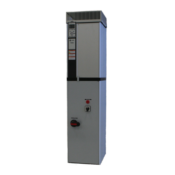
Vertical bypass/non bypass panel
Hide thumbs
Also See for TR200:
- Programming manual (297 pages) ,
- Instruction manual (205 pages) ,
- Operating instructions manual (85 pages)
Table of Contents
Advertisement
Operators Guide
TR200 Vertical Bypass/Non Bypass Panel
SAFETY WARNING
Only qualified personnel should install and service the equipment. The installation, starting up, and servicing
of heating, ventilating, and air-conditioning equipment can be hazardous and requires specific knowledge and
training. Improperly installed, adjusted or altered equipment by an unqualified person could result in death or
serious injury. When working on the equipment, ovserve all precautions in the literature and on the tags,
stickers, and labels that are attached to the equipment.
BAS-SVX49A-EN
August 2011
Advertisement
Table of Contents

Related Manuals for Trane TR200


Summary of Contents for Trane TR200
- Page 1 Operators Guide TR200 Vertical Bypass/Non Bypass Panel SAFETY WARNING Only qualified personnel should install and service the equipment. The installation, starting up, and servicing of heating, ventilating, and air-conditioning equipment can be hazardous and requires specific knowledge and training. Improperly installed, adjusted or altered equipment by an unqualified person could result in death or serious injury.
- Page 2 Safety Safety WARNING Grounding Correct protective grounding of the equipment must be EQUIPMENT HAZARD! established in accordance with national and local codes. The vertical bypass/non bypass panel contains dangerous Ground currents are higher than 3mA. voltages when connected to mains voltage. It is strongly recommended that all electrical work conform to the Safety Guidelines National Electrical Code (NEC) and all national and local...
- Page 3 Safety BAS-SVX49A-EN...
-
Page 4: Table Of Contents
Contents Contents 1 Introduction 1.1.1 Purpose of the Manual 1.1.2 Overview 1.1.3 Typical Bypass Operation 1.2 Bypass Circuits 1.2.1 Three-contactor Bypass 1.3 Bypass Options 1.3.1 Common Run/Stop with Bypass 1.3.2 Automatic Bypass 1.3.3 Run Permissive in Bypass 1.3.4 Basic Fire Mode in Bypass 1.3.5 Advanced Fire Mode in Bypass 1.3.6 Overload Protection 1.4 Bypass Platform Configurations... - Page 5 Contents 3.2.1 Lifting 3.2.2 Hoist or Overhead Lift 3.2.3 Forklift 3.2.4 Shipping Weights 3.3 Cooling 3.4 Electrical Installation 3.4.1 Component Identification & Customer Connection 3.4.2 Wire and Cable Access 4-15 3.4.3 Wire Size 4-19 3.4.4 Wire Type Rating 4-20 3.4.5 Terminal Tightening Torques 4-20 3.4.6 Input Line Connection 4-25...
- Page 6 Contents 6.1.5 ECB Hand/OFF/Auto 6.1.6 ECB Mode of Operation 6.1.7 Bypass Status Word Bit Examples 7-10 6.1.8 ECB Auto Bypass 7-10 6.1.9 ECB Run Permissive 7-11 6.1.10 ECB Overload 7-11 6.1.11 ECB Safety Interlock 7-12 6.1.12 ECB Common Run/Stop 7-12 6.1.13 ECB Advanced Fire Mode 7-13 6.1.14 ECB Fault Reporting...
- Page 7 Contents BAS-SVX49A-EN...
-
Page 8: Introduction
An important conjunction with a Trane variable frequency drive (VFD or feature of the ECB is the ability to accept commands from drive). To enable efficient handling of the equipment,... -
Page 9: Bypass Options
Introduction Contactor Drive Mode OFF Bypass Test Mode Mode Closed Open Open Closed Closed Open Open Open Open Open Closed Closed Table 1.1 Contactor Operation Figure 1.1 Basic Non Bypass Circuit 1.3.4 Basic Fire Mode in Bypass 1.3 Bypass Options This option switches the panel to bypass whenever a remote fire mode signal is given to the VFD through the 1.3.1 Common Run/Stop with Bypass... -
Page 10: Bypass Platform Configurations
Introduction Control Features EMB2 Safety Interlock 1.4 Bypass Platform Configurations Common Start / Stop Automatic Bypass The two bypass platform configurations are ECB and EMB2. Run Permissive The features available as options with each platform are listed in Table 1.2. The ECB, also listed below, has all option Basic Fire Mode features available. -
Page 11: Mode Selector Switch
Introduction the option panel door can be opened. (Bypass panel only.) • Disconnect without fuses. For user-supplied fuses option. (Bypass panel only.) • Main circuit breaker. A thermal/ magnetic current interrupt device using an ON/TRIP/OFF/RESET switch. When in the ON position, a trip fault removes power from the drive/bypass circuit and the switch moves to the TRIP setting. -
Page 12: Panel Configurations
Introduction 1.6.3 Panel Configurations The TR 200 Drive Series comes in two panel enclosure types. One is the non bypass and the other is the bypass. See Table 1.3 for descriptions and available options. Non bypass Bypass Drive plus both of the following: Drive with bypass: 1. -
Page 13: Panel Voltage And Frame Ratings
Table 1.4Table 1.4 defines the voltage and hp ratings of the frames sizes for the panel. See 8 Appendix for overall and mounting dimensions. Bypass Non Bypass Panel P2 (B3 - Drive) TR200 TR200 Volts VAC HP (KW) 208 & 230 7.5 (5.5) - 15 (11) 7.5 (5.5) - 15 (11) -
Page 14: Pre-Installation
Trane is willing to assist you to collect claims for loss or • Do not connect power factor correction damage, but willingness on our part does not make us capacitors between the drive and motor. -
Page 15: Harsh Environments
Pre-installation dirt. If the unit does not have power applied to it, supply a protective covering. It is important to ensure that the components stay as clean as possible. It may be necessary to clean the interior once construction is completed. •... -
Page 16: Installation
See the specifications label inside the cover of the unit for acceptable replacement drive fuses. A sample of this data can be seen in Table 3.6 208 V AC UL Motor Panel (TR200) Non Bypass Main Fuse (TR200) Drive Fuse (TR200) Transformer Fuse (TR200) - Page 17 Installation 230 V AC UL Motor Panel (TR200) Non Bypass Main Fuse (TR200) Drive Fuse (TR200) Transformer Fuse (TR200) HP (KW) Current & Bypass Bussman Bussman Bussman 7.5 (5.5) LPJ-35-SP JJN-50 10 (7.5) LPJ-45-SP JJN-50 15 (11) LPJ-70-SP JJN-60 20 (15)
-
Page 18: Internal Main Panel Fuses
Installation 3.1.3 Internal Main Panel Fuses Use only the specified fuse or an equivalent replacement for the internal main fuses. See the specifications label inside the cover of the unit for acceptable replacement main fuses. A sample of this can be seen in Table 3.6. Fuse Description Manufacturer... -
Page 19: Cooling
Installation Figure 3.2 Side Cooling Clearance Figure 3.1 Proper Lifting Method 3.3 Cooling • Only mount the drive and panel vertically. • Panels rely on the ambient air for cooling. It is important to observe the limitations on ambient air temperature. The maximum ambient temperature for all bypass panels is 40°C and 45°C for non bypass panels. -
Page 20: Electrical Installation
Installation WARNING 3.4 Electrical Installation INDUCED VOLTAGE! WARNING Run output motor cables from multiple drives separately. Hazardous Voltage! Induced voltage from output motor cables run together Disconnect all electric power, including remote disconnects can charge equipment capacitors even with the equipment before servicing. - Page 21 Installation Figure 3.4 Power Connections BAS-SVX49A-EN...
-
Page 22: Component Identification & Customer Connection
Installation 3.4.1 Component Identification & Customer Connection Mechanical layout drawings are intended to provide the installer or equipment user with component identification and location for that specific unit. Figure 3.5 represents a typical layout drawing. Table 3.8 provides definitions for drawing reference designators. - Page 23 Installation Figure 3.6 P2 Non Bypass Mechanical Layout Diagram. See Table 3.8 for reference designator definitions. BAS-SVX49A-EN...
- Page 24 Installation Figure 3.7 P3 Bypass Mechanical Layout Diagram. See Table 3.8 for reference designator definitions. BAS-SVX49A-EN...
- Page 25 Installation Figure 3.8 P3 Non Bypass Mechanical Layout Diagram. See Table 3.8 for reference designator definitions. 3-10 BAS-SVX49A-EN...
- Page 26 Installation Figure 3.9 P4 Bypass Mechanical Layout Diagram. See Table 3.8 for reference designator definitions. BAS-SVX49A-EN 3-11...
- Page 27 Installation Figure 3.10 P4 Non Bypass Mechanical Layout Diagram. See Table 3.8 for reference designator definitions. 3-12 BAS-SVX49A-EN...
- Page 28 Installation Figure 3.11 P5 Bypass Mechanical Layout Diagram. See Table 3.8 for reference designator definitions. BAS-SVX49A-EN 3-13...
- Page 29 Installation Figure 3.12 P5 Non Bypass Mechanical Layout Diagram. See Table 3.8 for reference designator definitions. 3-14 BAS-SVX49A-EN...
-
Page 30: Wire And Cable Access
• Control wiring should be isolated from power components inside the unit as much as possible. Trane has included hardware to allow for the separation. Figure 3.14 Non Bypass Panel Conduit Entry Diagram • See the mechanical layout drawings in through for connection details and recommended wire routing. - Page 31 Installation Figure 3.15 P2 Panel Figure 3.16 P3 Panel 3-16 BAS-SVX49A-EN...
- Page 32 Installation Figure 3.17 P4 Panel BAS-SVX49A-EN 3-17...
- Page 33 Installation Figure 3.18 P5 Panel 3-18 BAS-SVX49A-EN...
-
Page 34: Wire Size
Make all power connections with minimum 60 or 75°C/140 or 155°F rated copper wiring for installations in North America. 208 V AC Maximum Field Minimum Temperature Panel (TR200) Non Field Ground Wiring HP (KW) UL Motor Current Wiring Size Class B Wire Rating "°C"... -
Page 35: Wire Type Rating
Installation 460 VAC Maximum Field Field Ground Minimum Temperature Panel (TR200) Non Bypass HP (KW) UL Motor Current Wiring Size Class B Wiring Size Class B Wire Rating "°C" Copper & Bypass or C or C Conductor 15 (11) 10 AWG... - Page 36 Installation BAS-SVX49A-EN 3-21...
- Page 37 Installation 3-22 BAS-SVX49A-EN...
- Page 38 Installation BAS-SVX49A-EN 3-23...
- Page 39 Installation 3-24 BAS-SVX49A-EN...
-
Page 40: Input Line Connection
Installation Field Connection Tightening Torque lb-in (N-m) Temperature & Type Rating L1, L2, L3/Ground 25 (2.8) 25 (2.8) Use 75°C Copper Conductor 2T1, 2T2, 2T3/Ground 25 (2.8) 25 (2.8) Use 75°C Copper Conductor 25 (2.8) 25 (2.8) Use 75°C Copper Conductor Table 3.15 Sample Tightening Torque and Wire Rating Label 3.4.6 Input Line Connection WARNING... -
Page 41: Grounding (Earthing)
Installation • • Connect the 3-phase motor wiring to bypass Connect the ground wire directly to a reliable terminals T1 (U), T2 (V), and T3 (W). See the earth ground. Grounding studs are provided on connection drawing inside the cover of the unit. the back plate of the panel for grounding. -
Page 42: Serial Communication Bus Connection
Installation Programming Serial communication point maps, parameter settings, and other details for bypass option functionality are included in the serial communication materials supplied with the unit. Figure 3.19 Control Terminals Location EIA-485 terminal Jumper wire Control terminals Grounded restraining clips 3.4.10 Serial Communication Bus Connection The ECB reports serial communication data to host systems... -
Page 43: Drive Control Terminals
• A USB port, connector 4, is also available for use with the available on the Trane website. • Also provided are two Form C relay outputs that are in various locations depending upon the drive configuration and size. -
Page 44: Start Up
Start Up 4 Start Up Input power to the unit must be OFF and locked For multiple winding motors, the motor must be out per OSHA requirements. Do not rely on panel wired on run winding, not start winding. disconnect switches. Confirm motor FLA is equal to or less than WARNING maximum panel output current. -
Page 45: Inspection Prior To Start Up
Start Up 4.1.1 Inspection Prior to Start Up Before applying power to the unit, inspect the entire installation as detailed in Table 4.1. Inspect For Description Look for auxiliary equipment, switches, disconnects, or input fuses/circuit breakers that may reside on input power side of drive or output side to motor. - Page 46 Start Up within FLA of drive and balanced within CAUTION 3%. If incorrect, see 7.1 Start Up Trouble- MOTOR START! shooting for isolation procedures. Ensure that motor, system, and any attached equipment is Check motor current in bypass mode on the ready for start.
- Page 47 Start Up BAS-SVX49A-EN...
-
Page 48: Electromechanical Bypass (Emb2) Operation
Electromechanical Bypass (EMB2) Operation 5 Electromechanical Bypass (EMB2) Operation 5.1.1 Typical Control Connections for Common HVAC Applications Drive Terminal Parameter Number Parameter Name Value Number Value Name Function Digital I/O Mode External Interlock Term 27 mode Input External Interlock Term 29 Mode Output Auto Bypass Term 18 digital input... - Page 49 Electromechanical Bypass (E... Figure 5.1 Customer Side EMB2 Control Card Terminal Connections BAS-SVX49A-EN...
-
Page 50: Emb2 Auto Bypass
Electromechanical Bypass (EMB2) Operation • 5.1.2 EMB2 Auto Bypass All OFF = no auto bypass operation • Switch 1 only ON = 30 sec. delay General Information • Switch 2 only ON = 60 sec. delay Auto bypass allows a fault condition in the drive to •... -
Page 51: Emb2 Run Permissive
Electromechanical Bypass (E... 5.1.4 EMB2 Run Permissive 5.1.5 EMB2 Overload General Information General Information Run permissive allows a remote signal to notify the drive The overload device provides overcurrent protection for to start, indicating the system is safe to operate. Run the motor when running in bypass. -
Page 52: Emb2 Safety Interlock
Electromechanical Bypass (EMB2) Operation 5.1.7 EMB2 Fire Mode trip when pressed. Use the reset pushbutton to reset the overload after the test. General Information • Reset is used to reset the overload after it trips. If Fire mode runs the motor at full speed in bypass and is the overload is still hot, wait until the motor intended to ignore common safety, overload, and mode reaches normal operating temperature before... -
Page 53: Emb2 Switches
Electromechanical Bypass (E... Fault Reporting Function Setup • Fault reporting status is connected to connector X55, output terminals 5, 6, and 7. 5.1.9 EMB2 Switches Mode selector switch. A panel mounted Drive/OFF/Bypass/Test selector switch is used to electrically select whether the motor is controlled by the drive (M1 and M2 contactors), connected to the full-speed bypass (M3 contactor), or disconnected from both. -
Page 54: Electronically Controlled Bypass (Ecb) Operation
Electronically Controlled Bypass (ECB) Opera- tion 6 Electronically Controlled Bypass (ECB) Operation keypad Display Menu keys 6.1 Electronically Controlled Bypass (ECB) Operation Menu navigation Control keys 6.1.1 Overview Programming and display are provided by the drive’s local control panel. (keypad See Figure 6.1) Information provided in this section is intended to enable the user to connect control wiring, program functions, and operate the ECB and its optional features. -
Page 55: Ecb Control Card
Electronically Controlled B... Parameter Parameter name Setting title Setting Function 5-01 Term 27 Mode Input Customer Interlock 5-02 Term 29 Mode Output Auto bypass 5-10 Term 18 digital input Start Common run/stop 5-11 Term 19 digital input Run Permissive Run Permissive 5-12 Term 27 digital input External Interlock... - Page 56 Electronically Controlled Bypass (ECB) Opera- tion Figure 6.2 ECB Control Card Terminal Connections BAS-SVX49A-EN...
- Page 57 Electronically Controlled B... Input Conn. Term. Function Type Digital input for safety stop User supplied dry contact Common User supplied dry contact Factory use only No function Factory use only Factory use only Factory use only Digital input for remote bypass enable User supplied dry contact Digital input overrides system to Bypass Mode ignoring all User supplied dry contact...
-
Page 58: Ecb Drive Or Bypass Selection
Electronically Controlled Bypass (ECB) Opera- tion 6.1.3 ECB Drive or Bypass Selection Use the keypad and display to switch between the motor running in drive mode or bypass when operating in local control. The display in operating mode is shown below. 1. - Page 59 Electronically Controlled B... NOTE! Pressing [Info] at any time displays tips and guidelines for performing the function currently activated. BAS-SVX49A-EN...
-
Page 60: Ecb Programming
Electronically Controlled Bypass (ECB) Opera- tion 6.1.4 ECB Programming Use the keypad and display for programming ECB functional options. All programming options appear in numbered parameters. Parameters are arranged in groups by related functions. Programming is performed by accessing the parameters through a menu and selecting from displayed options or entering numerical values. -
Page 61: Ecb Hand/Off/Auto
Electronically Controlled B... 6.1.5 ECB Hand/OFF/Auto General Information The [Hand on], [Off Reset], and [Auto on] keys on the keypad control both the drive and bypass (see Figure 6.1). [Drive Bypass] allows the user to locally select drive or bypass mode of operation. It does not necessarily start or stop the motor. Prior to Enabling Hand/Off/Auto •... - Page 62 Electronically Controlled Bypass (ECB) Opera- tion • Auto bypass mode: When in drive mode, auto bypass is a timed interval that allows a fault condition in the drive to activate running the motor in bypass without operator intervention. Mode of Operation Select •...
-
Page 63: Bypass Status Word Bit Examples
Electronically Controlled B... 6.1.7 Bypass Status Word Bit Examples Motor running and bypass in drive mode. Status word 22 hexadecimal converts to 00000100010 binary. Binary External interlock fault (open) and bypass in bypass mode. Status word 208 hexadecimal converts to 01000001000 binary. -
Page 64: Ecb Run Permissive
Electronically Controlled Bypass (ECB) Opera- tion Run Permissive Function Setup • See the drive manual or support materials for programming and wiring to the drive control terminals. • Wire the output run request to the drive output terminals selected, and program the terminals for run request. -
Page 65: Ecb Safety Interlock
Electronically Controlled B... Operation bypass ignores all run commands except for fire mode Overloads and motors are both rated by class. The class is operation, when applicable. The drive display indicates defined by the NEC to determine the maximum time to alarm 221, bypass interlock, meaning the problem is trip. -
Page 66: Ecb Advanced Fire Mode
6.1.13 ECB Advanced Fire Mode The drive monitors the ECB card communication and detects when communication stops. An ECB card failure or communication error could cause this. Contact Trane using General Information the phone number on the back of this manual for Drive operation in advanced fire mode is programmable. - Page 67 Electronically Controlled B... 6-14 BAS-SVX49A-EN...
-
Page 68: Start Up Troubleshooting
Start Up Troubleshooting 7 Start Up Troubleshooting 7.1.1 Option Panel Alarm and Warnings Code Title Definition Number Overload Trip Motor overload has tripped. Indicates excess motor load. Check motor and driven load. To reset, press [Off Reset]. Then, to restart the system, press [Auto on] or [Hand on]. Bypass Interlock Bypass interlock has opened and caused the motor to stop. - Page 69 Start Up Troubleshooting Symptom Possible cause Test Solution Missing input power See startup guide for voltage checks. Correct voltage at source. Missing or open fuses or circuit See open fuses and tripped circuit Reset circuit breaker. If fuses, check for breaker tripped breaker in this section for possible opens with power removed from panel.
- Page 70 Start Up Troubleshooting Symptom Possible cause Test Solution Application problem Perform startup procedures. Check If current is too high, reduce the load panel output motor current at full on the motor. speed and check for excessive over current. Panel problem Perform startup procedures.
- Page 71 Start Up Troubleshooting Symptom Possible cause Test Solution Motor overloaded Motor is drawing too much current for Perform startup and verify motor current the application. is within specifications. If not, reduce the load on the motor. Loose connections Look for signs of overheating on Perform pre-startup check for loose Overload trips connections to OL.
-
Page 72: Appendix
Appendix 8 Appendix 8.1.1 Dimensions P2 NON- P3 NON- P4 NON- P5 NON- P2 BYPASS P3 BYPASS P4 BYPASS P5 BYPASS BYPASS BYPASS BYPASS BYPASS 8.86 [225.0] 9.11 [231.4] 9.57 [243.0] 9.57 [243.0] 12.69 [322.3] 12.69 [322.2] 15.13 [384.3] 15.13 [384.2] 6.66 [169.1] 29.92 [759.9] 41.77 [1061.0]... -
Page 73: Mechanical Diagrams
Appendix 8.1.2 Mechanical Diagrams Figure 8.1 P2 Bypass BAS-SVX49A-EN... - Page 74 Appendix Figure 8.2 P2 Non-bypass BAS-SVX49A-EN...
- Page 75 Appendix Figure 8.3 P3 P4 P5 Bypass BAS-SVX49A-EN...
- Page 76 Appendix Figure 8.4 P3 P4 P5 Non-bypass BAS-SVX49A-EN...
-
Page 77: Typical Wiring Diagrams
Appendix 8.1.3 Typical Wiring Diagrams Figure 8.5 EMB2 with Control Relay, Part 1 BAS-SVX49A-EN... - Page 78 Appendix Figure 8.6 EMB2 with Control Relay, Part 2 BAS-SVX49A-EN...
- Page 79 Appendix Figure 8.7 EMB2, Part 1 BAS-SVX49A-EN...
- Page 80 Appendix Figure 8.8 EMB2, Part 2 BAS-SVX49A-EN...
- Page 81 Appendix Figure 8.9 ECB, Part 1 8-10 BAS-SVX49A-EN...
- Page 82 Appendix Figure 8.10 ECB, Part 2 BAS-SVX49A-EN 8-11...
- Page 83 Appendix Figure 8.11 ECB with Control Relays, Part 1 8-12 BAS-SVX49A-EN...
- Page 84 Appendix Figure 8.12 ECB with Control Relays, Part 2 BAS-SVX49A-EN 8-13...
- Page 85 Appendix Figure 8.13 Non-bypass 8-14 BAS-SVX49A-EN...
- Page 86 HVAC systems, comprehensive building services, and parts. For more information, visit www.Trane.com. Trane has a policy of continuous product and product data improvement and reserves the right to change design and specifications without notice. © 2011 Trane All rights reserved...
Need help?
Do you have a question about the TR200 and is the answer not in the manual?
Questions and answers