
Related Manuals for Hirschmann EAGLE30-0402 series


Summary of Contents for Hirschmann EAGLE30-0402 series
-
Page 1: User Manual
User Manual Installation Industrial Security Router EAGLE20/30 EAGLE30-0402... EAGLE20-0400... Installation EAGLE20/30 Technical support Release 05 10/2013 https://hirschmann-support.belden.eu.com... - Page 2 In addition, we refer to the conditions of use specified in the license contract. You can get the latest version of this manual on the Internet at the Hirschmann product site (www.hirschmann.com). Printed in Germany Hirschmann Automation and Control GmbH Stuttgarter Str.
- Page 3 Contents Safety instructions About this manual Description General device description Device name and product code Combination options Device views 1.4.1 Front view 1.4.2 Rear view Power supply 1.5.1 Operating voltage characteristic value K 1.5.2 Operating voltage characteristic value C Ethernet ports 1.6.1 10/100 Mbit/s twisted pair port 1.6.2 100/1000 Mbit/s F/O port Display elements...
- Page 4 Installing an SFP transceiver (optional) Connecting the terminal blocks 2.5.1 Operating voltage characteristic value K 2.5.2 Operating voltage characteristic value C 2.5.3 Signal contact Installing terminal blocks, switching on the supply voltage Connecting network cables 2.7.1 10/100 Mbit/s twisted pair port 2.7.2 100/1000 Mbit/s F/O port Insert data in label area Basic set-up...
-
Page 5: Safety Instructions
Safety instructions Certified usage Only use the device for application cases that are described in the Hirschmann product information, including this manual. Only operate the device according to the technical specifications. Supply voltage Note: The supply voltage is only connected with the chassis via protective elements. - Page 6 The cross-section of the protective conductor cable is the same size as or bigger than the cross-section of the voltage supply cables. The connection cables used are permitted for the specified temperature range. Relevant for North America: The supply voltage lines are made of copper wire, which is suitable for ambient temperatures of up to at least 167 °F (75 °C).
-
Page 7: Grounding The Device
Connect the protective conductor with the ground screw before you set up the other connections. When removing the connections, you remove the protective conductor last. For supply voltages with protective conductor connections: first connect the protective conductor before connecting the lines for the supply voltages. -
Page 8: General Safety Instructions
Qualification requirements for personnel Qualified personnel as understood in this manual and the warning signs, are persons who are familiar with the setup, assembly, startup, and operation of this product and are appropriately qualified for their job. This includes, for example, those persons who have been: ... - Page 9 In accordance with the above-named EU directive(s), the EU conformity declaration will be at the disposal of the relevant authorities at the following address: Hirschmann Automation and Control GmbH Stuttgarter Str. 45-51 72654 Neckartenzlingen Germany Tel.: +49 1805 141538...
- Page 10 Appropriate testing has established that this device fulfills the requirements of a class A digital device in line with part 15 of the FCC regulations. These requirements are designed to provide sufficient protection against interference when the device is being used in a business environment. The device creates and uses high frequencies and can also radiate high frequencies, and if it is not installed and used in accordance with this operating manual, it can cause radio transmission interference.
-
Page 11: About This Manual
About this manual The “Installation” user manual contains a device description, safety instructions, a description of the display, and the other information that you need to install the device. The following manuals are available as PDF files on the CD/DVD supplied: ... -
Page 12: Description
You will find these manuals as PDF files on the enclosed CD/DVD, or you can download them from the Internet on the Hirschmann product pages (www.hirschmann.com). The Hirschmann network components help you ensure continuous communication across all levels of the company. Installation EAGLE20/30... -
Page 13: Device Name And Product Code
Device name and product code The device name corresponds to the product code. The product code is made up of characteristics with defined positions. The characteristic values stand for specific product properties. Item Product Character Value for the characteristic characteristic istic value 1 ... - Page 14 Item Product Character Value for the characteristic characteristic istic value 24 ... 25 Approvals CE, FCC, EN 61131-2, EN 60950-1 “Z9” + cUL 508, (UL 60950-1) “Z9” + cUL 508, (UL 60950-1), ISA 12.12 Class 1 Div. 2 “Z9” + IEC 61850-3, Substation applications IEEE 1613 “V9”...
- Page 15 Figure 1: Example of a device name: EAGLE20-0400999TT999SCCZ9 Installation EAGLE20/30 Release 05 10/2013...
-
Page 16: Combination Options
Combination options Item 1 ... 5 6 ... 7 9 ... 10 11 ... 12 13 ... 15 16 ... 17 18 19 ... 20 22 ... 23 24 ... 25 Product Data rate Number Number of Configur Configur Cellular WAN port Temperatur Operating Certifications... -
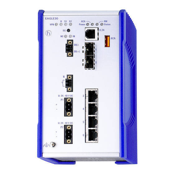
Page 17: Device Views
Device views 1.4.1 Front view LED display elements for device status V.24 interface USB interface Optional: 2 × SFP slot for 100/1000 Mbit/s F/O port 4 × 10/100 Mbit/s twisted pair ports Grounding screw Power supply connection alternatively, 2 × Operating voltage ... -
Page 18: Rear View
1.4.2 Rear view Slot for the SD card Knurled screw Power supply 1.5.1 Operating voltage characteristic value K A 3-pin terminal block is available to supply the device. You will find further information under “Operating voltage characteristic value K” on page 1.5.2 Operating voltage characteristic value C For the redundant supply of the device, two 2-pin terminal blocks are... -
Page 19: Ethernet Ports
Ethernet ports You can connect terminal devices and other segments on the ports of the device via twisted pair cables or F/O cables. 1.6.1 10/100 Mbit/s twisted pair port This port is an RJ45 socket. The 10/100 Mbit/s twisted pair port offers you the ability to connect network components according to the IEEE 802.3 10BASE-T/100BASE-TX standard. -
Page 20: Device State
1.7.1 Device state These LEDs provide information about conditions which affect the operation of the whole device. Power Status Display Color Activity Meaning Power Power supply — None The supply voltage is too low. Yellow Lights up Device variants with redundant voltage supply: The supply voltages 1 or 2 are on. -
Page 21: Additional Status Information
1.7.2 Additional status information VPN RD S1 S2 Display Color Activity Meaning (no function in the existing device version) 1.7.3 Input Display Color Activity Meaning (no function in the existing device version) 1.7.4 Port state These LEDs display port-related information. During the boot phase, they indicate the status of the boot process. -
Page 22: Sd Card Interface
VT 100 terminal settings Stopbit 1 bit Handshake Parity none The socket housing is electrically connected to the front panel of the device. The V.24 interface is electrically insulated from the supply voltage. RJ11 RJ11 n.c. Figure 2: Pin assignment of the V.24 interface and the DB9 connector Note: You will find the order number for the terminal cable, which is ordered separately, in the Technical Data section. -
Page 23: Input/Output Interfaces
Figure Operation VCC (VBus) − Data + Data Ground (GND) Table 5: Pin assignment of the USB interface Input/output interfaces 1.9.1 Signal contact Figure 3: Signal contact: 2-pin terminal block with screw locking In the state on delivery, the signal contact indicates the device status. It can be configured using the device management. -
Page 24: Installation
Installation The devices have been developed for practical application in a harsh industrial environment. On delivery, the device is ready for operation. The following steps should be performed to install and configure a device: Unpacking the package and checking the content ... -
Page 25: Installing And Grounding The Device
Installing and grounding the device WARNING FIRE HAZARD Install the device in a fire protected enclosure according to EN 60950-1. Failure to follow these instructions can result in death, serious injury, or equipment damage. WARNING Solely for device variants with operating voltage characteristic value K: ELECTRIC SHOCK Only install this device in a switch cabinet or in an operating site with limited access, to which only maintenance staff have access. -
Page 26: Grounding The Device
Figure 5: Mounting on the DIN rail 2.3.2 Grounding the device For safety reasons, make sure you only connect the ground wire before you set up the other connections. The housing is grounded via the separate ground screw on the bottom left of the front panel. -
Page 27: Connecting The Terminal Blocks
Note: Only use Hirschmann SFP transceivers. See “Accessories” on page 44. Connecting the terminal blocks WARNING ELECTRIC SHOCK Ground the device before connecting the power supply. Disconnect the grounding last. Solely connect a supply voltage that corresponds to the type plate of your device. -
Page 28: Operating Voltage Characteristic Value C
Type of the voltages Size of the supply voltage Connections that can be connected DC voltage Rated voltage range DC Plus terminal of the supply voltage 60 V ... 250 V −/N Minus terminal of the supply Voltage range DC incl. voltage maximum tolerances Protective conductor... -
Page 29: Signal Contact
Type of the voltages Size of the supply voltage Connections that can be connected DC voltage Rated voltage range DC Plus terminal of the supply voltage 24 V ... 48 V − Minus terminal of the supply Voltage range DC incl. voltage maximum tolerances 18 V ... -
Page 30: Installing Terminal Blocks, Switching On The Supply Voltage
Installing terminal blocks, switching on the supply voltage Note: Relevant for North America: The torque for tightening the supply voltage terminal block on the device is 4.5 lb in (0.51 Nm). The torque for tightening the signal contact and input terminal block on the device is 0.34 Nm (3 lb in). -
Page 31: Basic Set-Up
Basic set-up The IP parameters must be entered when the device is installed for the first time. The device provides the following options for configuring IP addresses: Entry via V.24 connection Entry using the HiDiscovery protocol via the application HiDiscovery or Industrial HiVision ... -
Page 32: Maintenance And Service
Hirschmann is continually working to improve and develop our software. You should regularly check whether there is a new version of the software that provides you with additional benefits. You will find software information and downloads on the product pages of the Hirschmann website. -
Page 33: Disassembly
Disassembly Removing the device Disconnect the data lines. Switch off the supply voltage. Disconnect the terminal blocks. Disconnect the grounding. Note: For safety reasons, make sure you disconnect the grounding from all connections last. To remove the device from the DIN rail, press the device downwards and pull it out from under the DIN rail. - Page 34 Figure 10: Deinstalling an SFP transceiver Installation EAGLE20/30 Release 05 10/2013...
-
Page 35: Technical Data
Technical data General technical data Weight EAGLE..-..999S.. ca. 1,2 kg EAGLE..-..999T.. ca. 1,5 kg EAGLE..-..999E.. Power supply Relevant for North America: Class 2 Operating Nominal voltage DC 24 V ... 48 V Class 2 voltage Voltage range DC 18 V ... -
Page 36: Digital Input
Digital input Maximum permitted input voltage range −32 V DC … +32 V DC Input voltage, low level, status "0" −0,3 V DC … +5,0 V DC Input voltage, high level, status "1" +11 V DC … +30 V DC Maximum input current at 24 V input voltage 15 mA Input characteristic according to IEC 61131-2 (current-... - Page 37 114,7 6,55 4.52 inch 0.26 2.76 98,29 3.87 Figure 12: Dimensions of device variants with operating temperature type E and type T. For the designation, compare “Device name and product code” on page Installation EAGLE20/30 Release 05 10/2013...
- Page 38 EMC and immunity EMC interference Standard Marine Railway Sub-station emission applications applications applications applications (trackside) Radiated emission EN 55022 Class A — — Class A GL Guidelines — EMC 1 — — FCC 47 CFR Part 15 Class A —...
- Page 39 EMC interference Standard Marine Railway Sub-station immunity applications applications applications applications (trackside) EN 61000-4-3 80 MHz ... 2700 MHz — — 20 V/m — IEEE 1613 80 MHz ... 1000 MHz — — — 35 V/m Fast transients (burst) EN 61000-4-4 AC/DC supply connection ±...
- Page 40 EMC interference Standard Marine Railway Sub-station immunity applications applications applications applications (trackside) Damped oscillation - AC/DC supply connection EN 61000-4-12 line/ground — — — 2.5 kV IEEE C37.90.1 EN 61000-4-12 line/line — — — 1 kV IEEE C37.90.1 Damped oscillation - data line EN 61000-4-12 line/ground —...
- Page 41 Network range Note: The line lengths specified for the transceivers apply for the respective fiber data (fiber attenuation and BLP/dispersion). Product Wave Fiber System Example Fiber code length attenuation for F/O line attenuation dispersion M-SFP-... length -SX/LC... MM 850 nm 50/125 µm 0-7.5 dB 0-550 m...
- Page 42 Product Wave Wave Fiber System Example Fiber Dispersion code length length attenuat for F/O attenuati M-SFP- line BIDI... length Type A LH 1490 nm 1590 nm 9/125 µm 5-24 dB 23-80 km 0.25 19 ps/(nm×km) LH/LC dB/km Type B LH 1590 nm 1490 nm 9/125 µm 5-24 dB 23-80 km 0.25 19 ps/(nm×km) LH/LC dB/km...
-
Page 43: Scope Of Delivery
Power consumption/power output, order numbers The order numbers correspond to the product codes of the devices. Siehe „Device name and product code“ auf Seite 13. Device name Maximum Power output power consumption EAGLE20-0400... 12 W 41 BTU (IT)/h EAGLE30-0402... 14 W 48 BTU (IT)/h Scope of delivery... - Page 44 Accessories Note: Please note that products recommended as accessories may have characteristics that do not fully correspond to those of the device. This may limit their possible usage in the overall system. Name Order number Terminal cable 943 301-001 AutoConfiguration Adapter ACA 21-USB 943 271-002 AutoConfiguration Adapter ACA 31...
- Page 45 If your device has a shippingcertification according to Germanischer Lloyd, the certification mark can be found printed on the device label. You will find out whether your device has other shipping certifications on the Hirschmann website under www.hirschmann.com in the product information.
- Page 46 Installation EAGLE20/30 Release 05 10/2013...
-
Page 47: A Further Support
Further Support Technical Questions For technical questions, please contact any Hirschmann dealer in your area or Hirschmann directly. You will find the addresses of our partners on the Internet at http://www.hirschmann.com Contact our support at https://hirschmann-support.belden.eu.com You can contact us in the EMEA region at ...
Need help?
Do you have a question about the EAGLE30-0402 series and is the answer not in the manual?
Questions and answers