Table of Contents
Advertisement
Quick Links
Download this manual
See also:
Operating Manual
Advertisement
Table of Contents

Related Manuals for UMS Hyprop

Summary of Contents for UMS Hyprop
- Page 1 User Manual © UMS GmbH München Art. no. HYPROP Version 01/2010 Author: an/tk/mn...
- Page 2 Saturate the samples Filling 4.2.1 Important cautions 4.2.2 Introduction 4.2.3 Refilling with the HYPROP service kit 4.2.3.1 Degassing the ceramic tip and tensiometer shaft 4.2.3.2 Degas the sensor head 4.2.3.3 Reassemble the HYPROP sensor head 4.2.4 Filling with vacuum pump 4.2.5...
- Page 3 HYPROP system 5.2.2.1 Properties 5.2.2.2 Configuration of a device 5.2.2.3 Configuration settings for HYPROP 5.2.3 Refilling window 5.2.4 Current readings 5.2.5 Stored readings Add the scale Perform a measuring campaign Starting conditions Measuring campaign window Configure the campaign Estimate the initial water content...
- Page 4 Parameter listing and describtion of the .csv table: 11.2 Technical specifications 11.2.1 Wiring configuration 11.3 Accessories 11.3.1 HYPROP extension and Accessories 11.3.2 Service kit 11.4 Units for soil water and matrix potentials 12 List of literature 13 Table of figures 14 Index...
-
Page 5: Hyprop System
HYPROP system HYPROP system Laboratory evaporation method according to WIND/SCHINDLER for the determination of unsaturated hydraulic conductivity and water retention characteristics of soil samples. 1.1 Safety instructions and warnings Electrical installations must comply with the safety and EMC requirements of the country in which the system is to be used. -
Page 6: Content Of Delivery
® tensioLINK USB converter ® tensioLINK T-piece junction plug 9 V mains power supply unit Scale* * only included in the starter set HYPROP-SW For available accessories see chapter “Accessories”. Fig. 1: Content of delivery 6/92... -
Page 7: Foreword
HYPROP system 1.3 Foreword Measuring systems must be reliable and durable and should require a minimum of maintenance to achieve target-oriented results and keep the servicing low. Moreover, the success of any technical system is directly depending on a correct operation. - Page 8 Furthermore, he developed the software SHYPFIT 2.0 to adapt the retention and conductivity functions to the measured data, and implemented it in the HYPROP calculation software. The thesis is documented in following publications: 1. Peters, A., and W. Durner (2008): Simplified Evaporation Method for Determining Soil Hydraulic Properties.
-
Page 9: Intended Use
HYPROP system is an extraordinary high tech soil laboratory system. 1.5 Intended use The intended use of the HYPROP system is the measurement and determination of water retention characteristics and unsaturated hydraulic conductivity as a function of water tension or water content in a soil sample. -
Page 10: Process Summary
Process summary Process summary 1. Preparation of sample and hardware 1.1. Fill HYPROP sensor unit(s) and Tensiometer shafts 1.2. Take samples with soil sampling rings 1.3. Saturate the soil samples 1.4. Drill the holes for the Tensiometer shafts 1.5. Place the sampling ring on the sensor unit 1.6. -
Page 11: Product Description
3.1 System components A measuring system can include one or several HYPROP assemblies (max. 20). A HYPROP assembly consists of a sensor unit and a sampling ring with a soil sample which is placed on each sensor unit. Sensor units are linked to a PC via the serial ®... -
Page 12: Pressure Transducers
Product description Sampling ring Tensiometer shaft for lower level incl. Silicone gasket ceramic tip Tensiometer shaft O-Ring, prevents for upper level incl. intrusion of soil ceramic tip O-Ring, seals Screw-in thread for the Tensiometers shafts with pressure transducer beneath Temperature sensor Fastener clip Sensor unit Fig. -
Page 13: Tensiometers
Product description 3.2.3 .2.3 Tensiometers Tensiometers Tensiometers measure the soil water tension or the matric potential. Tensiometers measure the soil water tension or the matric potential. These Tensiometers have a measuring range of +100 kPa These Tensiometers have a measuring range of +100 kPa (water pressure) to -85 kPa (water tension). -
Page 14: Temperature Sensor
Product description 3.2.4 .2.4 Temperature sensor Temperature sensor A temperature probe sits inside the small stainless steel pin on the A temperature probe sits inside the small stainless steel pin on the sensor unit. It measures the temperature of the soil sample. Although sensor unit. -
Page 15: Sampling Ring
Fig. 6: tensioVIEW for optimized usage with HYPROP (see chapter ”Performing a measuring campaign“.). The functions are activated whenever the bus recognizes that a HYPROP unit is connected. If a laboratory scale with serial RS232 or USB interface is used ®... -
Page 16: Get Ready To Start A Measuring Campaign
Get ready to start a measuring campaign Get ready to start a measuring campaign The following tools are required to prepare a HYPROP unit before a measuring campaign: Sampling ring, volume 250 ml Perforated saturation attachment A dish or bowl with minimum rim height 7 cm... -
Page 17: Saturate The Samples
Get ready to start a measuring campaign 4.1 Soil samples 4.1.1 Take soil samples Samples should be as fresh as possible. Please follow the guidelines for taking soil samples (described in DIN 4021, “Exploration by excavation and borings; sampling) Following a short instruction for soil sampling based on lecture notes from Prof. -
Page 18: Filling
Get ready to start a measuring campaign have a glossy appearance. Clayey soil will need the longest (several days). 4.2 Filling 4.2.1 Important cautions Caution: The Hyprop uses highly sensitive pressure transducers. Improper handling cause irreversible damage! Read the chapter about refilling in this manual first. - Page 19 Get ready to start a measuring campaign Be cautious when pulling off the tube as vacuum is inside! An abrupt negative pressure change on the water column might destroy the pressure transducer. Do not pull off the tube rapidly. Allow the pressure to be released through the end of the tube or pull off the tube slowly so the...
-
Page 20: Introduction
Ceramic tip: Do not touch the tip with your fingers. Grease, sweat or soap residues will influence the ceramic's hydrophilic performance. The HYPROP-service kit or a vacuum system and a PC/Laptop with ® tensioVIEW software are required for filling or refilling. - Page 21 Get ready to start a measuring campaign The HYPROP service kit includes: - Bottle of deionised water (1) - 2 reservoir syringes (2) - 2 vacuum syringes (with red O-ring at tip) (3) - 1 vacuum syringe with acrylic attachment (4)
- Page 22 Get ready to start a measuring campaign 4.2.3.1 Degas ceramic tip and Tensiometer shaft If the tip is completely dry just put the empty shaft in a beaker with de-ionized or distilled water and leave it overnight. Tensiometer shafts should never be filled from the inside. To avoid that air is trapped inside the ceramic the water must flow in one direction only from the outside into the interior.
- Page 23 Get ready to start a measuring campaign evacuated syringe to collect all Degas the water 1. Take the reservoir syringe bubbles from the wall of the with the short rubber tube. syringe. Pull up 10 ml of deionised or distilled water. Take care to 3.
- Page 24 Get ready to start a measuring campaign 2. Take off the tube from the take vacuum syringe but leave the shaft syringe with the 2 black spacers inside the tube. and the O-ring on the tube. Remove all air from the syringe. Pull up 10 ml water.
- Page 25 Get ready to start a measuring campaign 6. Now insert the threaded side 8. Carefully remove the tube Tensiometer shaft from the syringe nozzle and completely into the tube of the push out all air from the vacuum syringe. syringe. There should be no air Roll up the O-ring so the shaft inside the tube before inserting is securely fixed.
-
Page 26: Degas The Sensor Head
Get ready to start a measuring campaign 4.2.3.2 Degas the sensor head Avoid that the plug connector gets in contact with water. Take care that the piston never recoils abruptly as this might damage the pressure transducer (max. 3 bar)! 1. - Page 27 Get ready to start a measuring campaign 4. Reattach the tube and draw the syringe up again until the spacers snap in. The water now is being degassed. We recommend controlling the quality vacuum observing the refilling window in tensioVIEW. Fig.
- Page 28 Get ready to start a measuring campaign 4.2.3.3 Reassemble the sensor unit When screwing in the Tensiometer shaft into the thread of the sensor head it is very important to monitor the pressure in the ® refilling window in tensioVIEW The pressure sensor diaphragm is inside the small hole (ca.
- Page 29 Get ready to start a measuring campaign Push the silicone cap (or tube, see 7. Connect the sensor unit with fig. below) over the shafts to adapter cable and USB-converter ® protect the ceramic. to your PC and start tensioVIEW Click on “Refilling”...
- Page 30 Get ready to start a measuring campaign Fig. 29 30/92...
-
Page 31: Filling With Vacuum Pump
It might be better to re-establish the vacuum in intervals. Knock against the sensor unit every time you switch on the pump to loosen any bubbles. Fig. 30 customized vacuum system made by UMS 31/92... -
Page 32: Check The Hyprop
Get ready to start a measuring campaign 4.2.5 Check the HYPROP Wrap a dry paper towel around one ceramic tip to create a momentary dry ceramic surface. Now create an air current around the ceramic cup, e. g. by waving a sheet of paper. The reading should rise to -800 hPa within seconds. -
Page 33: Attach The Sampling Ring
Get ready to start a measuring campaign Attach the sampling ring 4.3.1 Auger the Tensiometer holes Rotate the auger while pulling it out of the sample. 1. Take the soil sample out of the deeper hole is. Then you the saturation dish. Place the know the correct position when auger positioning tool on the placing... -
Page 34: Assemble Sensor Unit And Sampling Ring
Get ready to start a measuring campaign 4.3.2 .3.2 Assemble sensor unit and sampling ring Assemble sensor unit and sampling ring Wipe off the ring surface after having drilled the holes. Wipe off the ring surface after having drilled the holes. Watch your mark. - Page 35 Get ready to start a measuring campaign 5. Before you can start the campaign the sample needs to be over-saturated again. To do so, carefully drip some water onto the soil surface This is required to create even starting conditions. 6.
-
Page 36: Set-Up The Hyprop
The next step is to connect the components with tensioLINK Up to 20 sensor units can be linked to a PC at the same time with the supplied bus cables and distributors. For this you require: The prepared HYPROP assembly HYPROP connection cable Adapter cable ®... -
Page 37: Connect Sensor Units
In the single device mode the HYPROP assembly remains on the In the single device mode the HYPROP assembly remains on the scale and the USB-cable is connected all the time. Therefore, it is scale and the USB-cable is connected all the time. -
Page 38: Connect The Scale
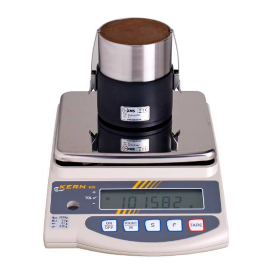
A laboratory scale with interface is required. If the type of scale is not in the following list, the scale is not supported and has to be send in to UMS (incl. manual and interface cable). Supported scales: Kern EG2200 (recommended) -
Page 39: Find Devices
(also see 6.1 Starting conditions p 48): 1. The scale should be placed on a vibration-free work table. 2. The work table should only be used for the HYPROP measurement. 3. The scale must be leveled out. Most scales have a bubble-level. -
Page 40: Device Window
Set-up the HYPROP Double-click on the device ® Fig. 40: tensioVIEW menu 5.2.2 Device window Detected devices will be displayed with their programmed names. Press the + symbol to see what readings parameter are available. Double-click on the name to open a menu window where all specifications and functions of this device are displayed. - Page 41 Set-up the HYPROP Depending on the authorization status, only parameters that can be edited are shown. To store a changed parameter in the device it has to be sent to the device by pressing the "Upload“ button. A message confirming the successful configuration will be displayed.
-
Page 42: Configuration Settings For Hyprop
Set-up the HYPROP 5.2.2.3 Configuration settings for HYPROP Those settings which are editable only for Power users are marked with an asterisk *. Parameters with related functions are bundled in one folder. tensioLINK Bus number ® tensioLINK bus number of the device Sub address ®... - Page 43 Overwrites old values (if you select „on“) if the memory is full Sensor measuring Continuous measuring Activate the quick updating of readings to receive the HYPROP readings instantly, for example during a refilling procedure. Measurements are taken in intervals of 50 ms. Note the rise in power consumption and that the reaction to serial commands might be slowed down.
-
Page 44: Refilling Window
Set-up the HYPROP 5.2.3 Refilling window This function is required when the HYPROP sensor head needs to be refilled or during assembly of sensor head and Tensiometer shafts (strictly recommended!!). When the Tensiometer shafts are screwed back into the sensor unit the pressure reading must be checked at any time to avoid that excess pressure destroys the pressure transducer. -
Page 45: Current Readings
Set-up the HYPROP 5.2.4 Current readings In this window you can display current values of the Tension Bottom , Tension top and Temperature, depending on the Parameter Interval. 5.2.5 Stored readings In this window you can download stored readings and delete stored... -
Page 46: Add The Scale
UMS are pre-set. There are two ways to add a new scale: 1. Click the right mouse button on HYPROP in the parent directory to open the “Add“ and “Add HYPROP device“ window. Click on „Add new Scales“. - Page 47 Set-up the HYPROP Select the scale type, for example “Kern EG2200“, the interface and the connection parameters. Then click on the Measure-Button. If a connection is established „zero“ is displayed for both status and reading. Click “OK“ to select the scale.
-
Page 48: Perform A Measuring Campaign
HYPROP assembly or of all assemblies measured at the same time. This information is stored in one file for further use. ® Familiarise yourself with the functions of tensioVIEW before you start a measuring campaign. - Page 49 4. The scale should be placed on a vibration-free work table. The work table should not be used for other purposes during a HYPROP measurement. 5. During a single mode measurement we strictly recommend to fix the cable of the sensor unit.
-
Page 50: Measuring Campaign Window
Perform a measuring campaign 6.2 Measuring campaign window There are two ways to open the measuring campaign window. 1. In the menu bar select <Tools> <HYPROP Measuring campaign> 2. Click this button: Fig. 46: tensioVIEW measuring campaign window 50/92... -
Page 51: Configure The Campaign
Perform a measuring campaign 6.3 Configure the campaign Open the measuring campaign window to configure the system. Enter file name and directory where you want to store the measuring campaign: Under <General parameters> enter the starting time of the campaign and the intervals when to weigh the samples (fig. - Page 52 Perform a measuring campaign To determine the starting water content you have the following options: 1. Automatically (default setting): this means starting water content weight determined approximate calculation so the measurement is graphically displayed and it's progression can be viewed. After the measurement the soil dry weight is determined precisely and then added.
- Page 53 Perform a measuring campaign Model The following calculation models are available (status December 2007): 1. van Genuchten 2. van Genuchten bimodal 3. Brooks & Corey Parameter Select in the menu <Model>. Click on <…> to set up the model parameters. Example for the model parameter according to van Genuchten: The parameters...
-
Page 54: Estimate The Initial Water Content
To estimate the water content before a measurement weigh the complete and saturated HYPROP assembly. The software will withdraw the tare weight of sensor unit and sampling ring. The difference is the sum of soil matter and water. The density of soil and water as well as the volume are known values with which the water content can approximately be calculated. -
Page 55: Zero Offset
Perform a measuring campaign 6.5 Zero offset An offset shift is caused by the different water columns inside both Tensiometers. Each of the two Tensiometers has a hanging water column inside the shaft, and as their shaft lengths are different they have a different offset. -
Page 56: Perform The Measurement
Perform a measuring campaign 6.6 Perform the measurement 6.6.1 Single unit mode and multiplex device mode In general there are two modes, the single unit mode and the multiplex devices mode. The following table shows the differences. Single unit mode Multiplex device mode Sensor unit... -
Page 57: Current Status Of The Measurement
Perform a measuring campaign 6.6.4 Start a spontaneou measurement In the function window you can optionally click on <measuring> to start measurement spontaneously (out constant measurement). 6.6.5 Current status of the measurement In the left upper window (”Current status“) the current readings are displayed. - Page 58 Perform a measuring campaign 6.6.6 Measurements in the „Single device mode“ Select “Single device mode” under “General Parameters” in the configuration window. Set up the parameters as described in the previous chapters. In the single device mode only one measuring interval is entered which is used for both tension and temperature measurement.
- Page 59 Fig. 48: Multiplex devices mode 6.6.6.1 Multiplex devices mode ® Connect all devices with tensioLINK to the HYPROP main unit. Click on “Multiplex devices mode” to start a scan. Note that a different tensioLINK address is given to each device (see chapter ”Configuration Settings”).
-
Page 60: Interrupt A Measuring Campaign
Perform a measuring campaign will automatically recognize which sample is put on the scale. The number of samples is limited to 20. A new menu opens on the screen showing information about the status and the routine of the weighing. Follow the given instructions (fig. -
Page 61: End Of A Measuring Campaign
Perform a measuring campaign 6.6.8 End of a measuring campaign A measuring campaign normally ends as soon as the first Tensiometer value reaches the end of its measuring range. The campaign does not stop automatically but must be stopped by the user. -
Page 62: Evaluation Of Readings
Perform a measuring campaign 6.7 Evaluation of readings Before starting the evaluation select an adequate model in the configuration menu to fit the curves (see chapter Configure the campaign 6.3). An evaluation is only possible if the campaign has been stopped and appropriate start and stop points are set. Pull the start and stop line to the proper position with the cursor. -
Page 63: Calculation And Fitting
Perform a measuring campaign The graph in fig. 50 shows the incline of both tension readings, in this example far beyond the boiling retardation range (beyond 95 kPa, depending on atmospheric pressure). The upper Tensiometer (light blue line) fails first and drops to end of the measuring range (gas bubbles inside the ceramic have bursted). -
Page 64: Export Readings And Calculations
<Export> in the menu bar. Export data not before a campaign has been terminated and the calculations have been executed (see chapter 6.4). The data of all involved HYPROP devices of this campaign are exported in csv format. Thus, the data can be opened for example 64/92... - Page 65 Excel. Diagrams are exported in jpg format. If functions were recorded the function parameters are exported as well. For each data type and each HYPROP device individual files are created. For the file name the sample name and the date is recommended but you may enter your own names and directory.
- Page 66 Perform a measuring campaign 6.10 Typical results for different soil Typical results for different soils after data export. Fig..52 : pF-WC curves ( kindly supported by Dr. Uwe Schindler, ZALF Müncheberg) 66/92...
-
Page 67: Trouble Shooting
Trouble shooting Trouble shooting Problem Possible cause and solution 1. It is not possible to achieve a If the tip is completely dry just put bubble free filling. the empty shaft in a beaker with deionised distilled water overnight. 2. The Tensiometer readings only Could depend on the soil type: rise very slowly for example sand has a poor... - Page 68 Trouble shooting and interrupts the water contact (see point 3) 8. At the beginning the lower This is caused by inaccuracy of the Tensiometer surpasses the upper sensors. Execute the “Zero offset“ to one which would indicate a negative compensate the water column shift. conductivity Eventually set the starting point to a later point.
-
Page 69: Service And Maintenance
Service and maintenance 8.1 Testing 8.2 Check the HYPROP 1. First check if the Tensiometers of the HYPROP need to be refilled (recommended always at initial use and after a complete measurement campaign): Connect the sensor unit with adapter cable and USB-converter to ®... -
Page 70: Check The Offset
(grain size 150...240). 8.4 Storage If the HYPROP should not be used for a year or more empty shaft and sensor head to avoid algae growth. Store both in a dry place. 70/92... -
Page 71: Theoretical Basics
Theoretical basics Theoretical basics 9.1 Evaporation method (overview) In a soil sampling ring two Tensiometers, comparable to the T5 model, are installed in two depths (z and z ). The middle between the sensing tips of the Tensiometers is the centre of the soil sample. The sample is saturated, closed on the bottom and placed on a scale. -
Page 72: Retention And Conductivity Functions
9.3 Retention and conductivity functions Normally hydraulic characteristics are described by parametric functions for With HYPROP three models can be chosen. These models can be adapted to measure data via a robust and non-linear optimizing procedure. 72/92... -
Page 73: The Van Genuchten/Mualem Modell
Theoretical basics 9.3.1 The van Genuchten/Mualem modell With this model the effective saturation the unsaturated conductivity K in relation to the matric potential h are predetermined by the following equation formula (van Genuchten, 1980): ... -
Page 74: The Brooks And Corey Model
Theoretical basics 9.3.3 The Brooks and Corey Model In the Brooks & Corey model the retention and conductivity function are defined as (Brooks and Corey, 1964): ... -
Page 75: Additional Notes
10.1.1 The bubble point of the porous cup The bubble point of a porous, hydrophilic structure is specified by the wetting angle and the pore size. The cups used for UMS Tensiometers have a bubble point far beyond the measuring range (8.8 bar). -
Page 76: Boiling Retardation
(unless the 8.8 bar range is irrelevant). It is possible to get further information from the known bubble point which is 8.8 bar for the HYPROP cups. The moment the tension reading rapidly drops to zero the soil has a tension of -880 kPa (+/- 20 kPa). -
Page 77: Vapour Pressure Influence On Pf/Wc
Additional notes 10.2 Vapour pressure influence on pF/WC If the temperature of a soil with a constant water content rises from 20°C to 25°C the soil water tension is reduced by about 0,85 kPa due to the increased vapour pressure which antagonizes the water tension. -
Page 78: Appendix
Appendix Appendix 11.1 Parameter list 11.1.1 Input Geometric variables: V [cm] FLOAT Soil sample volume [cm] FLOAT Height of Tensiometer 1 (over bottom of soil sample) [cm] FLOAT Height of Tensiometer 2 (over bottom of soil sample) L [cm] FLOAT Length of the soil sample For generating data points: INTERPOL INTEGER... -
Page 79: Output
Appendix data“ (JH-Paper). Otherwise w and w in equation (3) can be θ rated manually with parameters w and w θ FLOAT Rating for the retention data (only considered θ if IN_WEIGHTFLAG = FALSE.) wk FLOAT Rating of the conductivity data (only considered if IN_WEIGHTFLAG = FALSE.) The parameter collections “Control parameters for Levenberg- Marquardt algorithm“, “Control parameters for SCEUA algorithm“... -
Page 80: Parameter Listing And Describtion Of The .Csv Table
Root mean squared error of the function of Retentionscurve RMSELOGK Root mean squared error of the function of conductivity curve _PARVEC.csv Fittingparameter, please look at chapter HYPROP Theory _HYDFUNC.csv pF- Value Theta m³/m³ Water content cm/d Hydraulic conductivity _EVATH.csv PMEAN... - Page 81 Appendix 11.2 Technical specifications Material and dimensions Sensor unit housing Fibre-glass reinforced Polyamide Dimensions Height 60 mm, 80 mm Tensiometer shafts Ceramic sinter, bubble point > 200 kPa; 5 mm Shaft material Acrylic glass; 5 mm Total length Lower: 25 mm Upper: 50 mm Cable...
- Page 82 Appendix 11.2.1 Wiring configuration USB converter Signal Function Vout Supply +7…+10 VDC Supply minus n.c. n.c. n.c. RS485-A RS485-A twin 8-pin female plug RS485-B RS485-B twin n.c. Connection cable USB Converter T-junction Signal Function Vout Supply +6…+10 VDC RS485-A RS485-A twin Supply minus RS485-B...
-
Page 83: Hyprop Extension And Accessories
Appendix 11.3 Accessories 11.3.1 HYPROP extension and Accessories UMS art. no.: HYPROP-E Set consisting of: Sensor unit 2 Tensiometer shafts T-piece junction plug Connection cable with LEMO plug Note: a sampling ring is not included, please order separately. SZ250 Soil sampling ring, vol. 250 ml, stainless steel, outer diam. -
Page 84: Service Kit
Appendix 11.3.2 Service kit 11.4 Units for soil water and matric potentials kPa=J/kg 99,9993 -0,001 -0,01 -0,1450 99,9926 2,01 -100 -0,01 -0,1 -1,4504 2.53 -330 -0,033 -0,33 -4,9145 FK field 99,9756 capacitiy 2.93 -851 -85,1 -0,085 -0,85 -12,345 Tensiometer ranges* 99,9261 -1.000 -100... -
Page 85: List Of Literature
List of literature List of literature Brooks, R. H., and A. T. Corey (1964), Hydraulic properties of porous media, Hydrol. Pap. 3, 27 pp., Colo. State Univ., Fort Collins. Durner, W., 1994. Hydraulic conductivity estimation 703 for soils with heterogeneous pore structure. Water Resour. Res. 30, 211–223. -
Page 86: Table Of Figures
Fig. 22-24: Degas sensor head 26, 27 Fig. 25-29: Assembly 28, 29 Fig. 30 customized vacuum system made by UMS Fig. 31-33: Auger the Tensiometer holes Fig. 34-36: Assemble sensor unit and sampling ring 34, 35 Fig. 37: tensioLINK T-connector piece Fig. -
Page 87: Index
Clayey soil........17 hydraulic characteristics ....72 cleaning the threads......5 hydraulic conductivity......72 csv format ........64 Hyprop service kit ......20 Degas ceramic cup and shaft ..22 integral fit ........74 Degas the sensor head....26 internal pressure transducers ..12 degassed ........20 ion concentration ......77 de-ionised ........20... - Page 88 Index scale ..........46 semi permeable diaphragm ....13 sensor diaphragm ......28 short groove ........29 long groove ........29 SHYPFIT 2.0........8 soil samples ........17 Soil type ..........52 soil water pressure......5 soil water tension ....5, 12, 13 stainless-steel sampling ring...15 matric potential........13 starting conditions......48 measuring campaign....46, 48 surplus of water ......48 measuring head syringe....26...
- Page 89 Index 89/92...
- Page 90 Index 90/92...
- Page 91 Index 91/92...
-
Page 92: Your Addressee At Ums
D-81379 München Fax: +49-89-126652-20 Gmunderstr. 37 email: info@ums-muc.de Strictly observe rules for disposal of equipment containing electronics. Rücknahme nach Elektro G Within the EU: disposal through municipal waste WEEE-Reg.-Nr. DE 69093488 prohibited - return electronic parts back to UMS. 92/92...
Need help?
Do you have a question about the Hyprop and is the answer not in the manual?
Questions and answers