Table of Contents
Advertisement
Advertisement
Table of Contents

Related Manuals for Unitest Telaris 0751


Summary of Contents for Unitest Telaris 0751
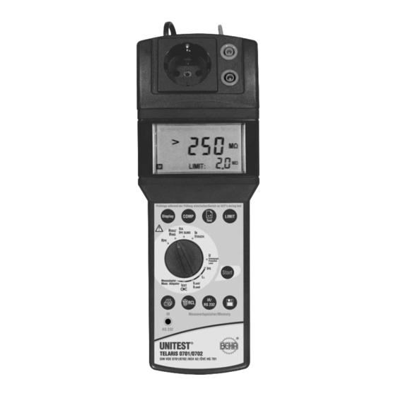
- Page 1 ® ® UNITEST Instruction Manual Cat. No. 9095 TELARIS 0751...
- Page 2 Content Content ....................Page Introduction ..................4 Model and Type Designation/Identification ........4 Product Description ................4 Scope of Supply ................5 Optional Accessories ..............5 Transport and Storage..............6 Safety Measures ................6 Appropriate Usage ................7 Operation Elements and Display ............8 Front Panel ..................8 LC Display..................10 General Information to Perform Measurements ......10 Explanations of Terms ..............11 Performing the Tests ..............14 Performing Tests in compliance with ..........15...
- Page 3 Content Measuring the PE earth leakage current (PE current) and the Differential Current with Schuko Measurement Adapter (Option) ........36 Function Test, Measurement of the Load Current with Schuko Measurement Adapter (Option) ..........40 Current Measurement using external Current Clamp Adapters, with Current Clamp Adapter (Option)..42 UUTs equipped with Three-phase Connection ........44 6.10 Messung des Ersatz-Geräteableitstromes ........45 6.11 Messung des Ersatz- Patientenableitstromes ........47...
-
Page 4: Introduction
An additional external Schuko Measurement tained herein can result in serious bodily injury Adapter may be connected to the TELARIS 0751 to or appliance damage. measure PE resistance currents, differential cur- rents, and load currents. Optionally you may also connect a current clamp adapter to measure PE re- sistance currents. -
Page 5: Scope Of Supply
Measurement adapter (to test appliances equipped with a three-phase connection): 1.3 Scope of Supply CEE 5 pole, 16 A Cat. No. 1240 1pc TELARIS 0751 CEE 5 pole, 32 A Cat. No. 1241 1pc Test lead equipped with test probe (appliance mounted) -
Page 6: Transport And Storage
3.0 Safety Measures • shows obvious damage • does not carry out the desired measurements The UNITEST TELARIS 0701/0702 has been de- • has been stored for too long under un- signed and checked in accordance with the safety favourable conditions regulations for Electronic test and Measurement •... -
Page 7: Appropriate Usage
Appropriate Usage 3.1 Appropriate Usage The appliance may only be used under those conditions and for those purposes for which it was built. The appliance may not be used for measure- ments in electrical distribution systems! The appliance may only be connected to cor- rectly wired and protected mains sockets, pro- tected with maximum 16 A! When modifying or changing the appliance, the... -
Page 8: Operation Elements And Display
Operation Elements and Display 4.0 Operation Elements and Display 4.1 Front Panel Explanation of the individual operation and display elements Figure 4.1: Appliance view... - Page 9 Operation Elements and Display 1. Mains connection plug, to connect the test ap- 10. Key “Store”, to save a measurement. pliance to the power supply 230 V +10%/-15%, 50 Hz. The test appliance may only be con- 11. Key “Send”, for data transfer of stored data to nected to a mains plug protected with a fuse of the PC via interface adapter (optional).
-
Page 10: Lc Display
LC-Display/General Information to Perform Measurements 4.2 LC-Display The test appliance and the Schuko Measure- ment Adapter may only be operated on a cor- rectly wired and earthed mains socket, pro- 20 21 tected with maximum 16 A! The test socket, the measurement connectors in parallel to the test socket, and the PE test connector may not be connected to external voltage to avoid test appliance damage. -
Page 11: Explanations Of Terms
The appliance UNITEST TELARIS 0701/0702 ments stipulated within VDE 0750/IEC 60601-1, in easy and the appliance UNITEST TELARIS particular when observing the admissible leakage 0701/0702 use the direct measurement proce- current. It is characterised by the symbol... - Page 12 Instrument connected to the mains by means of fixed connections which can only be removed using The Schuko Measurement Adapter (Option) of tools. the appliance UNITEST TELARIS 0701/0702 al- lows to perform the measurement using with Casing leakage current: the differential current procedure.
- Page 13 I are equipped with an formed. earth connector. The Schuko Measurement Adapter (option) of the appliance UNITEST TELARIS 0701/0702 allows the PE resistance current measurement in compliance with the direct measurement procedure and the differential current proce-...
-
Page 14: Performing The Tests
Explanations of Terms / Performing the Tests PE resistance (earth bond): 5.2 Performing the Tests We are dealing with the PE resistance of the mains The accident prevention prescriptions (German connection point (earth connector of the mains Unvallverhütungsvorschrift BGV A 2 for "Electrical plug) to all touchable, metal UUT casing parts which Systems and Equipment", issued by the profes- have to be connected to the PE resistance. -
Page 15: Performing Tests In Compliance With
Performing Tests in compliance with DIN VDE 0701 4a.) Measurement of PE resistance Current 5.3 Performing Tests in compliance with (for appliances of protection class I) DIN VDE 0701, Part 1 (issue 2000-09) The limit value amounts to 3.5 mA. DIN VDE 0701 defines the requirements regarding -at appliances with heating elements and a the electrical safety for electrical appliances. -
Page 16: Performing Tests In Compliance With
Performing Tests in compliance with DIN VDE 0702 4.) Measurement of substitute leakage current 5.4 Performing tests in compliance with The limit value amounts to: DIN VDE 0702, Part 1 (issue 1995-11) 7 mA for appliances of protection class I with a DIN VDE 0702 defines the test procedures and limit heating capacity of <... - Page 17 Performing Tests in compliance with DIN VDE 0751 2.) - Measurement of protective earth conductor 5.5 Performing Tests in compliance with resistance (for instruments pertaining to pro- DIN VDE 0751, Part 1 (Edition 2001-10) tection class I) DIN VDE 0751 stipulates the requirements for the The limit value is: electrical safety on medical, electrical instruments - 0.3 Ω...
- Page 18 Performing Tests in compliance with DIN VDE 0751 Table 1: Limit values for leakage currents Leakage current in mA in mA Contact surface TYP B TYP BF Instrument leakage current, in general Instrument leakage current for instruments in compliance with remarks 1 and 3 Instrument leakage current for instruments in compliance with remark 2 Instrument leakage current for instruments pertaining to protection class II and for instruments with conductible,...
- Page 19 Performing Tests in compliance with DIN VDE 0751 4.) Measurement of the insulation resistance 6 ) –Evaluation of the Documentation and Tests Only for old generation medical devices, plea- 6.1) Evaluation se refer to DIN VDE 0751 Part 1, Appendix E. The safety evaluation of INSTRUMENTS/SYSTEMS must be performed by a specialised person in elec- In case of doubt regarding the perfect condition of...
-
Page 20: Performing Individual Tests
The PE resistance connection via an additional connection must be removed when performing the measurement. For the appliance UNITEST TELARIS 0751 the test current is an AC current. The key ”Display” (17) is used to display the measurement val- ues for both polarities during active measure- ment. - Page 21 Continue with the PE resistance test for all test lead resistance (please refer to chapter 6.1.4). other touchable, conductive parts of the UUT. Connect the UNITEST TELARIS 0751 via the The measurement results can be saved by mains plug (1) to a functional and correct wired pressing the key “Store”...
- Page 22 PE resistance can be determined. ter 6.1.4. Continue with the PE resistance test for all Connect the UNITEST TELARIS 0751 via the other touchable, conductive parts of the UUT. mains plug (1) to a functional and correct wired and grounded mains socket.
- Page 23 Measurement of the PE resistance benachbarte Steckdose Prüfling Prüfling Figure 6.2: Measurement of the PE resistance for Figure 6.3: Measurement of the PE resistance for fixed installed appliances appliances not equipped with a mains plug...
- Page 24 Compensation of the Test Lead Resistance 6.1.4 Compensation of the Test Lead Resistance The appliance TELARIS 0751 allows to compensate the test lead resistance and the resistance of test ac- cessories resistance up to a value of 1,00 Ω. For compensation, please proceed as follows: Connect the PE test connection ‘Probe’...
-
Page 25: Measuring The Insulation Resistance
General Information regarding the Measurement of the Insulation Resis- Performing the measurement: tance Connect the UNITEST TELARIS 0751 via the The insulation resistance may only be per- mains plug (1) to a functional and correctly formed after successful PE resistance test. - Page 26 Measuring the Insulation Resistance For appliances of protection class II or III con- nect, in addition, the ‘PE’ socket (5) to all touch- able, conductive casing parts of the UUT, please refer to Figure 6.6.This is also applica- ble for conductive parts of class I appliances which are NOT connected to PE.
- Page 27 Performing the measurement: regarding the saving of measurement values, please refer to section 7.1 and 7.2. Connect the UNITEST TELARIS 0751 via the mains plug (1) to a functional and correct wired and grounded mains socket. Turn the ‘Measurement function” selection switch (15) to position ‘RINS’.
-
Page 28: Measuring The Substitute Leakage Current
Performing the measurement: urement for all other touchable, conductive casing parts of the UUT. Connect the UNITEST TELARIS 0751 via the mains plug (1) to a functional and correct wired The measurement results can be saved by and grounded mains socket. - Page 29 Measuring the Substitute Leakage Current Figure 6.8: Measuring the substitute leakage cur- Figure 6.9: Measuring the substitute leakage cur- rent for appliances of protection class I rent for appliances of protection class II...
- Page 30 Performing the measurement: pressing the key “Store” (10). For references regarding the saving of measurement values, Connect the UNITEST TELARIS 0751 via the please refer to section 7.1 and 7.2. mains plug (1) to a functional and correctly wired and grounded mains socket.
-
Page 31: Measuring The Touch Current
The measurement has to be performed for both after successful PE resistance test. positions of the mains plug . The higher of both values has to be considered. The UNITEST The UUT is put into operation during this test, TELARIS 0751 displays the symbol (22) i.e. - Page 32 (approx. 2 kΩ) to the blue "PE” socket (5). The blue "PE” sock- Connect the UNITEST TELARIS 0751 via the mains et (5) is during the measurement directly con- plug (1) to a functional and correctly wired and nected to the PE resistance of the mains plug grounded mains socket.
- Page 33 Measuring the Touch Current Read the measurement value from the LC dis- play (6). If the limit value display is active, the symbol ‘LIMIT’ (21) indicates that the limit value has been exceeded. Continue the touch current test for all other touchable, conductive casing parts of the UUT.
-
Page 34: Measuring The Protection Level Of Overvoltage Protection Devices (Varistors)
Overvoltage Protection Devices (varistors) Carrying out measurement: 6.5.1 General Information for Measuring Connect the UNITEST TELARIS 0751 via the the Protection Level mains plug (1) to a functional and correct wired and grounded mains socket. The protection level or the response voltage of over- voltage protection devices can be measured using Turn the ‘Measurement function”... - Page 35 Measuring the Protection Level of Overvoltage Protection Devices (varistors) PE L The measurement may be started and stopped manually. After approx. 15 seconds, the meas- urement is automatically terminated to avoid any overload of the tested overvoltage protec- tion devices. PE L Prüfling Prüfling...
-
Page 36: With Schuko Measurement Adapter (Option)
Measuring the PE earth leakage current An external Schuko Measurement Adapter must be 6.6 Measuring the PE earth leakage current connected to the TELARIS 0751 (Cat. No. 9091) to (PE current) and the Differential Current measure the PE resistance current, the differential with Schuko Measurement Adapter current, and the load current. - Page 37 The measurement must be performed for both positions of the mains plug. The higher of both values have to be considered. As a reference, the UNITEST TELARIS 0751 displays the sym- (22). The limit value for the PE current DIN VDE 0701/0702 amounts to 3.5 mA.
- Page 38 Read the second value from the LC display Performing the measurement: (16). The higher measurement value of both measurement values has to be considered and Connect the UNITEST TELARIS 0751 via the recorded. mains plug (1) to a functional and correctly wired and grounded mains socket.
- Page 39 Read the second value from the LC display Performing the measurement: (16). The higher measurement value of both measurement values has to be considered and Connect the UNITEST TELARIS 0751 via the recorded. mains plug (1) to a functional and correctly wired and grounded mains socket.
-
Page 40: Function Test, Measurement Of The Load Current With Schuko Measurement Adapter (Option)
To complete a test procedure, the appliance tected at maximum 16 A! UNITEST TELARIS 0751 offers the function test fa- cility. This test checks the UUT function and meas- The maximum output current of the mains ures the load current consumption. - Page 41 6.7.2 Function Test including Measurement of the Load Current (ILOAD) Performing the measurement: Connect the UNITEST TELARIS 0751 via the mains plug (1) to a functional and correctly wired and grounded mains socket. Connect the Schuko Measurement Adapter via the mains plug to a functional and correctly wired and grounded mains socket.
- Page 42 6.8 Current Measurement using external Current Clamp Adapter (IEXT) Current Clamp Adapters, Performing the measurement: Current Clamp Adapter (Option) Connect the UNITEST TELARIS 0751 via the mains plug (1) to a functional and correct wired 6.8.1 General Information regarding the and grounded mains socket.
- Page 43 Current Measurement using external Current Clamp Adapters Messadapter (optional) Figure 6.17: Measuring the PE current using a cur- rent clamp adapter...
-
Page 44: Uuts Equipped With Three-Phase Connection
The optional UNITEST Three-phase adapters 1240 and 1241 allow the direct connection of three-phase appliances to the UNITEST TELARIS 0751 test sock- Figure 6.18: Measuring the PE resistance for UUTs equipped with three-phase connection. Figure 6.20: Three-phase adapter 16 A (Cat. No. - Page 45 Performing the measurement: akage Current According to DIN VDE 0751, Part 1:2001-10, the Connect the UNITEST TELARIS 0751 via the measurement of the auxiliary instrument leakage mains plug (1) to a functional and correct wired current is an alternative measurement procedure to and grounded mains socket.
- Page 46 Measurement of the Auxiliary Instrument Leakage Current Figure 6.23: Measurement of the auxiliary instru- Figure 6.24: Measurement of the auxiliary instru- ment leakage current for instruments pertaining to ment leakage current for instruments pertaining to protection class I protection class II * * The measurement is only performed if contact surfaces of type F are available.
- Page 47 Measurement of the Auxiliary Patient Leakage Current 6.11 Measurement of the Auxiliary Patient Leakage Current 6.11.1 General Information regarding the Auxiliary Patient Leakage Current According to DIN VDE 0751, Part 1:2001-10, the measurement of the auxiliary patient leakage cur- rent is an alternative measurement procedure to de- termine the leakage current.
- Page 48 6.11.2 Measurement of the Auxiliary Patient Leakage Current (IEPA) Performing the measurement: z.B. Heizdecke, Connect the UNITEST TELARIS 0751 via the Bewegungsschiene mains plug (1) to a functional and correct wired and grounded mains socket. Turn the ‘Measurement function” selection switch (15) to position ‘IEPA’.
- Page 49 Measurement of the Auxiliary Patient Leakage Current Table 5: Limit values for the auxiliary leakage current Source: Table F.1 of DIN VDE 0751, Part 1:2001-10 Leakage current in mA in mA Contact surface TYP B TYP BF Auxiliary instrument leakage current - within protective earth conductor or parts connected to the protective earth - Instruments with mineral insulation and instruments...
-
Page 50: Storing, Printing, And Data Transfer
Storing, Printing and Data Transfer 7.0 Storing, Printing 7.2 Saving Measurement Data and Data Transfer To save the measurement data, please proceed as follows: After every completed measurement, the user has the possibility to save the measurement result by Perform a measurement. pressing the key “Store”... -
Page 51: Viewing Measurement Data
Switch on the printer and set the interface pa- rameter on the protocol printer in compliance To view measurement data, please proceed as fol- with the TELARIS 0751 (9600 Baud, 8 data bit, lows: 1 Stopbit, no parity). Briefly press the key “Clear/Recall” (13). The last memory location number is displayed. -
Page 52: Deleting Saved Measurement Data/View The Memory Location Number
Deleting Saved Measurement Data/View the Memory Location Number 7.5.3 Delete all Saved Measurement Values: 7.5 Deleting Saved Measurement Data/View the Memory Location Number Press the key “Clear/Recall” (13) and keep it de- It is possible to delete the last measurement value pressed. -
Page 53: Infrared Interface, Send Measurement Data
“Store” (10), see also section 7.1 and 7.2 Apply the Interface adapter (Cat. No. 1157) to TELARIS 0751. Connect interface cable via 9pole D-sub con- nector to serial interface of PC (ie COM 1). Call the "es control 0701/0702” Software (please refer to user manual "es control 0751”). -
Page 54: Internal Fuses
9.1 Display after Fuse Blown interval can be extended on to 3 years. If the appliance TELARIS 0751 displays the meas- urement values described below during the meas- urement, the respective fuse has blown. -
Page 55: Technical Data
Technical Data 11.0 Technical Data Function PE resistance (RPE) according to EN 61557-4, DIN VDE 0413, Part 4, Display range:........0.05 Ω... 19.99 Ω Measurement range:......0.1 Ω ... 1.99 Ω Resolution: ........0.01 Ω Accuracy: ........± (10% rdg. + 3 Digits) Limit value: ........0.3 Ω and 1.0 Ω Test current: ........≥... - Page 56 Technical Data Function Touch current ILEAK according to DIN VDE 0701/0702, Part 1 Display range:........0.01 mA … 1.999 mA Measurement range:......0.1 mA … 1.99 mA Resolution: ........0.001 mA Accuracy: ........± (10% rdg. + 3 Digits) Limit value: ........0.25 and 0.5 mA Internal resistance: ......approx.
- Page 57 Technical Data Function Protection Level of overvoltage devices (VProt Level) Display rangee: ........50 ... 500 V (DC) ............31 ... 312 V (AC) Calculation:........UAC=UDC/1.6 Measurement range:......50 ... 500 V DC Resolution: ........1 V Accuracy: ........± (10% rdg. + 3 Digits) Test voltage: ........approx. 500 V DC Test current: ........>...
- Page 58 Technical Data General Technical Data Display:..........3 -digit. LC-Display Temperature Ranges Reference Temperature Range: ..+23 °C (± 2 °C), 40...60 % rel. humidity Working Temperature: ....0 °C ... + 40 °C, max. 85 % rel. humidity (not condensing) Storage Temperature: ......–20 °C ... + 60 °C, max. 85 % rel. humidity (not condensing) Memory: ..........600 values, approx.
- Page 59 Technical Data Schuko-Measurement Adapter (Option) Measurement Functions: Earth Current, Differential Current, Load Current Output: 0...1 V AC Function Earth Current and Differential Current Display Range: ........0.25 mA … 19.00 mA Measurement range:......0.25 mA … 19.00 A Accuracy: ........± (5% rdg. + 50 µA) Frequency Range: ......40 Hz...100 kHz Frequency response:......according.
- Page 60 24 Month Warranty Qualitätszertifikat • Certificate of Quality Certificat de Qualité • Certificado de calidad Die BEHA-Gruppe bestätigt The BEHA Group confirms Le groupe BEHA déclare que El grupo BEHA declara que el hiermit, dass das erworbene herein that the unit you have l´appareil auquel ce document producto adquirido ha sido ca- Produkt gemäß...
-
Page 61: Month Warranty
24 month Warranty UNITEST appliances are subject to strict quality con- trol. However, should the appliance function improp- erly during daily use, you are protected by our 24 months warranty (valid only with invoice). We will repair free of charge any defects in work- manship or material, provided the appliance is re- turned unopened and untampered with, i.e. - Page 64 CH. BEHA GmbH Elektronik · Elektrotechnik In den Engematten 14 79286 Glottertal/Germany Tel.: +49 (0)76 84/ 80 09 -0 Fax: +49 (0) 76 84/ 80 09- 410 Techn. Hotline: +49(0)76 84 / 80 09 -429 internet: http://www.beha.com Reg.No. 3335 e-mail: info@beha.de 03/2006 Subject to technical changes without notice! PTEB90950001...
Need help?
Do you have a question about the Telaris 0751 and is the answer not in the manual?
Questions and answers