
Related Manuals for Unitest TELARIS EARTH


Summary of Contents for Unitest TELARIS EARTH
- Page 1 ® UNITEST Bedienungsanleitung Best.-Nr.: 8986 Instruction Manual Cat. No. 8986 E Mode d´emploi Réf. 8986 F ® TELARIS ERDE ® TELARIS EARTH...
-
Page 2: Table Of Contents
Inhaltsverzeichnis Seite 1.0 Einleitung/Lieferumfang..................2 2.0 Transport und Lagerung..................3 3.0 Sicherheitsmaßnahmen..................3 4.0 Allgemeines zur Erdmessung ................4 4.1 Einflüsse auf die Meßgenauigkeit...............5 5.0 Bedienelemente / Display.................. 6 6.0 Inbetriebnahme....................7 6.1 Erdwiderstandsmessung (Zweileitermethode)...........7 6.2 Erdwiderstandsmessung (Dreileitermethode............. 7 6.3 Erdwiderstandsmessung (Vierleitermethode)............9 7.0 Displayanzeigen....................11 8.0 Energiemanagement .................. -
Page 3: Transport Und Lagerung
Einschalten eine Aklimatisierung von mindestens 2 Stunden. Sicherheitsmaßnahmen Das UNITEST Telaris Erde wurde gemäß den Sicherheitsbestimmungen für elektronische Meß- und Prüfgeräte gebaut und hat das Werk in sicherheitstechnisch einwandfreiem Zustand verlassen. Um diesen Zustand zu erhalten, muß der Anwender die Sicherheits-... -
Page 4: Allgemeines Zur Erdmessung
Das Meßgerät darf nur an spannungsfreie Erder angeschlossen werden. Allgemeines zur Erdmessung: (siehe auch Begriffserklärungen Seite 5) TELARIS ERDE eingebauten Erdungsmessung handelt es sich um Bei der im UNITEST ® eine echte Erdwiderstandsmessung. Die Messungen erfolgen netzunabhängig, die Stromversorgung wird durch die eingebauten Batterien sichergestellt. Die Erdwiderstände werden mit dem Strom-Spannungs-Meßverfahren ermittelt. -
Page 5: Einflüsse Auf Die Meßgenauigkeit
umgebenden Erdreich abhängig ist. Geht man von einem gleichartig beschaffenen Erdreich aus, mit gleicher Temperatur und gleicher Feuchtigkeit, bilden sich um den Erder Spannungstrichter von konzentrischer Form. Je niederohmiger der Erdwiderstand ist, desto kleiner sind die Spannungstrichter. Gemessen wird bei der Erdwiderstandsmessung der Spannungsfall, erzeugt von einem bekannten konstanten Strom über den zu messen- den Erdwiderstand. -
Page 6: Bedienelemente / Display
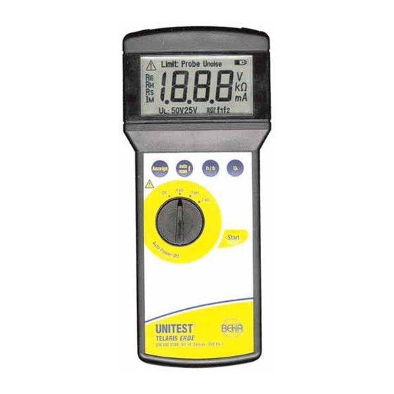
5.0 Bedienelemente Anzeigen im Display (siehe auch 7.0 Displayanzeigen): 1) Achtung Symbol... 2) Limit: Probe/Unoise 3) Batteriezustandsanzeige 4) Einheitenanzeige (ist abhängig von Auswahl (8)) für V, kΩ, mA 5) Frequenzanzeige f1=127Hz/ f2=140Hz 6) automatische/manuelle Frequenzwahl 7) Berührungsspannung 8) Meßgrößenanzeige Bedienelemente 9) Anschlußbuchsen für die Meßleitungen: Hilfserder....(H).. -
Page 7: Inbetriebnahme
Inbetriebnahme Vor der Inbetriebnahme ist die Bedienungsanleitung aufmerksam zu lesen. Erdwiderstandsmessung (Zweileitermethode) Die Widerstandsmessung mit der Zweileitermethode dient z.B. der Widerstandsmessung zwischen einem vorhandenen, bekannten und guten Erder und einem neu gesetzten Erder. Messungen in gefährlicher Nähe elektrischer Anlagen sind nur nach Anweisung einer verantwortlichen Elektrofachkraft und nicht alleine durchzuführen. - Page 8 Konstantstrom hervorgerufene Spannungsfall zwischen Sonde und Erder gemessen und hieraus RE ermittelt und angezeigt. 4 Ordnen Sie die Erdspieße für Hilfserder, Sonde, Erder wie in Bild 6.2 dargestellt, möglichst in einer Linie an. 4 Der Abstand zwischen Sonde und Erder bzw. Sonde und Hilfserder muß...
-
Page 9: Erdwiderstandsmessung (Vierleitermethode)
Erdwiderstandsmessung (Vierleitermethode nach Wenner) (nur mit Zubehörset, Best.:1048, möglich !) Messungen in gefährlicher Nähe elektrischer Anlagen sind nur nach Anweisung einer verantwortlichen Elektrofachkraft und nicht alleine durchzuführen. Für eine vorläufige Berechnung des Ausbreitungswiderstandes eines Erders ist die Kenntnis des spezifischen Erdwiderstandes notwendig. Der Widerstand kann nicht direkt abgelesen werden, der angezeigte Wert muß... - Page 10 Tabelle 6.3.1: Hinweise zur Auswertung der Meßergebnisse (nach DIN VDE 0413 Teil 7) Bodenbeschaffenheit Erdungswiderstand Erdungswiderstand Staberder Banderder 3m tief 5m tief 5m lang 10m lang Moorboden / Sumpf 10Ω 5Ω 12Ω 6Ω Ackerboden / Lehm 33Ω 17Ω 40Ω 20Ω Feuchter Sandboden 66Ω...
-
Page 11: Displayanzeigen
Displayanzeigen Meldung Ursache Hinweis auf Grenzwertüberschreitung in einer Meßgröße Probe Unterbrechung / Vertauschung S - ES (4 pol) Unterbrechung / Vertauschung S - E (3 pol) Unterbrechung H-E (2 pol) Limit Unterbrechung H-E (4/3 pol) Unoise Fremdspannung hat zulässigen Wert überschritten, Meßwerte entsprechen nicht mehr den Spezifikationen. -
Page 12: Wartung
10.0 Wartung Das Meßgerät benötigt bei einem Betrieb gemäß der Bedienungsanleitung keine besonde- re Wartung. 10.1 Reinigung Sollte das Gerät durch den täglichen Gebrauch schmutzig geworden sein, kann es mit einem feuchten Tuch und etwas mildem Haushaltsreiniger gesäubert werden. Bevor Sie mit der Reinigung beginnen, vergewissern Sie sich, daß das Gerät ausge- schaltet und von allen Stromkreisen getrennt ist. -
Page 13: Kalibrierintervall
Wird das Gerät über einen längeren Zeitraum nicht benutzt, sollten die Batterien ent- nommen werden. Sollte es zu einer Verunreinigung des Gerätes durch ausgelaufene Batteriezellen gekommen sein, muß das Gerät zur Reinigung und Überprüfung in unser Werk eingesandt werden. 12.0 Kalibrierintervall Um die angegebenen Genauigkeiten der Meßergebnisse zu erhalten, muß... - Page 14 Luftfeuchtigkeit:....80% bei -10°C...40°C 12 Monate Garantie UNITEST-Geräte unterliegen einer strengen Qualitätskontrolle. Sollten während der tägli- chen Praxis dennoch Fehler in der Funktion auftreten, gewähren wir eine Garantie von 12 Monaten (nur gültig mit Rechnung). Fabrikations- oder Materialfehler werden von uns kostenlos beseitigt, sofern das Gerät ohne Fremdeinwirkung und ungeöffnet an uns...
-
Page 15: Introduction/Scope Of Supply
Contents Page Introduction/Scope of Supply................15 Transport and Storage..................16 Operator´s Safety................... 16 General Information concerning Earth Measurement........17 Influence on Measurement Accuracy...............18 Control Elements / Display................19 Commissioning....................20 Earth Resistance Measurement (two-wire method).........20 Earth Resistance Measurement (three-wire method)........20 Earth Resistance Measurement (four-wire method)........22 Display Indications.................. -
Page 16: Transport And Storage
The UNITEST ® TELARIS EARTH is characterised by the following features: • Determination of earth resistance or specific earth resistance • 2, 3, and 4-wire measurements possible • Measurement in compliance with the Wenner method • Measurement current exceeds 10mA •... -
Page 17: General Information Concerning Earth Measurement
Prior to usage, inspect electronic load for external damage.Prior to any operation, ensure that the connecting leads used and the electronic load are both in perfect condition. If the operator’s safety can no longer be guaranteed, the instrument is to be put out of service and protected against use. -
Page 18: Influence On Measurement Accuracy
4.1 Influence on Measurement Accuracy Noise voltages present at ground connections may influence the measurement result. Interference voltage influence is very low for the instrument TELARIS EARTH. A precise filter suppresses all interference whose frequencies are different with respect to the res- pective measurement frequency. -
Page 19: Control Elements / Display
5.0 Control Elements Indications in Display (Also refer to display indications in chapter 7.0): 1) Warning symbol... 2) Limit:/Probe/Unoise 3) Battery condition indication 4) Indication of units (depending on the selection made (8)) for V, kW, mA 5) Frequency indication f1=127Hz/ f2=140Hz 6) Automatic/manual frequency selection 7) Contact voltage... -
Page 20: Commissioning
6.0 Commissioning Prior to commissioning, carefully read the instruction manual. 6.1 Earth Resistance Measurement (two-wire method) Resistance measurement by using the two-wire method is used to measure, e.g. the resistance between an available, known and good ground connection and a newly instal- led ground. - Page 21 auxiliary ground "H" and ground "E". The voltage drop between probe and ground is measured via probe input "S", and consequently the earth resistance is determined and displayed. 4 Locate earth rods for auxiliary ground, probe and ground, in one line if possible, as described in figure 6.2.
-
Page 22: Earth Resistance Measurement (Four-Wire Method)
Earth Resistance Measurement (four-wire method in line with the Wenner principle and only possible with the accessory set, order number:1048!) Measurements in dangerous proximity to electrical systems should only be carried out in conjunction with clear instructions from a responsible electrical specialist and must not be carried out alone. - Page 23 Table 6.3.1: References to evaluate measurement results (in compliance with DIN VDE 0413 Part 7) State of the earth resistance earth resistance ground bar ground connection flat ground connection 3m deep 5m deep 5m long 10m long marshy soil/swamp 10Ω 5Ω...
-
Page 24: Display Indications
7.0 Display Indications Message Cause Reference to exeeding the threshold value of a measurement variable Probe interruption / exchange S - ES (4 pole) interruption / exchange S - E (3 pole) interruption H-E (2 pole) Limit interruption H-E (4/3 pole) Unoise external voltage has exceeded admissible value, measurement values do no longer correspond to the specifications... -
Page 25: Maintenance
10.0 Maintenance When using the instrument in compliance with the instruction manual, no special mainte- nance is required. 10.1 Cleaning If the instrument is dirty after daily usage, it is advised to clean it by using a damp cloth and a mild household detergent. Prior to cleaning, ensure that the instrument is switched off and disconnected from the external voltage supply and any other instruments that may be connected (such as the EUT, control instruments, etc.). -
Page 26: Calibration Interval
If an instrument is not used over an extended time period, the accumulators or batteries must be removed. Should the instrument be contaminated by leaking battery cells, the instrument has to be returned for cleaning and inspection to the factory. 12.0 Calibration Interval The instrument has to be periodically calibrated by our service department in order to ensure the specified accuracy of measurement results. - Page 27 Height above NN:..........up to 2000m Relative humidity:........... 80% at -10°C...40°C 12 month Warranty UNITEST instruments are subject to strict quality control. However, should the instrument function improperly during daily use, you are protected by our 12 months warranty (valid only with invoice).
- Page 28 ® TELARIS ERDE a été développpe et construit selon DIN Le Contrôleur de terre UNITEST VDE 0413, Partie 5 et livré en état sûr. Ce contrôleur de terre UNTEST a été concu et fabri- qué selon les reconnaissances de techniques de sécurité les plus récentes.
-
Page 29: Transport Et Stockage
Le UNITEST ® TELARIS ERDE se caractérise par els points suivant: • détermination de la résistance de la mise à terre ou de la résistance spécifique • mesures à 2, 3 et 4 fils possibles • mesure selon la méthode Wenner •... -
Page 30: Information Générale Concernant Mesure De Terre
Avant toute utilisation, vérifier que la charge électronique n’ait pas de dommages extérieurs. Un appareil détérioré peut être dangereux. Eviter toute utilisation volontaire ou non. La sécurité n’est plus assurée lorsque l’appareil : • est manifestement endommagé • n’effectue pas les mesures désirées •... -
Page 31: Influences Sur La Précision De La Mesure
4.1 Influences sur la précision de la mesure Des tensions parasites peuvent influencer le résultat de mesure. L’influence de tensions parasites est très réduite pour l’appareil TELARIS ERDE. Un filtre de précision supprime toutes les interférences dont les fréquences sont différentes par rapport à la fréquence de mesure respective. -
Page 32: Fonctions / Affichage
5.0 Eléments de contrôle Indications sur l’affichage: 1) Symbole Achtung... 2) Seuil:/Sonde/Unoise 3) Indication de la pile 4) Indication des unités (selon la sélection effectuée (8)) pour V, kΩ, mA 5) Indication de la fréquence f1=127Hz/ f2=140Hz 6) Sélection de la fréquence automatique / manuelle 7) Tension de contact 8) Indication des variables de mesure Eléments de contrôle... -
Page 33: Mise En Service
Mise en service Avant la mise en service, lire soigneusement le mode d’emploi. 6.1 Mesure de la résistance de la mise à terre (méthode à deux fils) Les mesures à proximité dangereuse de systèmes électriques ne sont à effectuer que d’après les instructions d’un spécialiste en électricité... - Page 34 intensité constante est introduite dans le sol via les sorties de la terre auxiliaire "H" et la terre "E". La chute de tension entre la sonde et la terre, causée par l’intensité directe, est mesurée par l’intermédiaire de l’entrée de la sonde "S". Par conséquent, RE est déter- minée, puis affichée.
-
Page 35: Mesure De Résistance De La Mise À Terre (Méthode À Quatre Fils)
Mesure de la résistance de la mise à terre (méthode à quatre fils / selon Wenner) / (uniquement possible avec kit d’accessoires référence:1048!) Les mesures à proximité dangereuse de systèmes électriques ne sont à effectuer que d’après les instructions d’un spécialiste en électricité et dans aucun cas seul. Pour un calcul préliminaire de la diffusion de la résistance d’une terre, il faut disposer de la résistance spécifique d’une terre. - Page 36 Table 6.3.1: Références pour l’évaluation des résultats de mesure (selon DIN VDE 0413 section7) condition de terre résistance de la mise résistance de la mise sonde band 3m bas 5m bas 10m de grande taille marais 10Ω 5Ω 12Ω 6Ω champ terre / glaise 33Ω...
-
Page 37: Indications D'affichage
7.0 Indications d’affichage Message Raison Référence aux dépassement de seuil d’une variable de mesure Sonde interruption / échange S - ES (4 pôle) interruption / échange S - E (3 pôle) interruption H-E (2 pôle) Seuil interruption H-E (4/3 pôle) Unoise tension extérieure a dépassée la valeur admissible, les valeurs de mesures ne correspondent plus aux spécifications... -
Page 38: Entretien
10.0 Entretien Aucun entretien n’est requis lors de l’utilisation conforme au présent mode d’emploi 10.1 Nettoyage Si l’appareil s’avère sale dû à l’utilisation quotidienne, nous recommandons le nettoyage à l’aide d’un chiffon humide et d’un détergent ménager doux. Avant tout nettoyage, s’assurer que l’appareil soit éteint et déconnecté de toute source de tension externe et de tout autre instrument connecté... -
Page 39: Intervalle De Calibrage
Si l’appareil reste inutilisé pendant une période prolongée, il est conseillé de retirer les piles. En cas d’une contamination de l’appareil causée par des fuites de piles, il faut retourner l’appareil à notre usine pour nettoyage et vérification. 12.0 Intervalle de calibrage L’appareil est à... - Page 40 Conditions d’environnement: Humidité relative:..........80% pour -10°C...40°C Catégorie de surtension.:........ CAT III / 300V vers terre Degré de pollution:..........2 Hauteur sur NN:..........jusqu’à 2000m Plages de température:........0°C...40°C 12 mois de garantie Les appareils UNIWATT ont subi un contrôle individuel de qualité. Ces appareils sont cou- verts par une garantie de 1 an, pièces et main-d’oeuvre (facture d’achat).
Need help?
Do you have a question about the TELARIS EARTH and is the answer not in the manual?
Questions and answers