
Related Manuals for National Instruments NI 4350


Summary of Contents for National Instruments NI 4350
- Page 1 NI 4350 User Manual Temperature and Voltage Measurement Instruments NI 4350 User Manual May 1998 Edition Part Number 321566B-01 © Copyright 1997, 1998 National Instruments Corporation. All rights reserved.
- Page 2 Netherlands 0348 433466, Norway 32 84 84 00, Singapore 2265886, Spain 91 640 0085, Sweden 08 730 49 70, Switzerland 056 200 51 51, Taiwan 02 377 1200, United Kingdom 01635 523545 National Instruments Corporate Headquarters 6504 Bridge Point Parkway Austin, Texas 78730-5039 USA Tel: 512 794 0100...
-
Page 3: Important Information
Important Information Warranty The NI 4350 instruments are warranted against defects in materials and workmanship for a period of one year from the date of shipment, as evidenced by receipts or other documentation. National Instruments will, at its option, repair or replace equipment that proves to be defective during the warranty period. - Page 4 Installation and Configuration Software Installation ..................... 2-1 Hardware Installation....................2-1 Configuration ........................ 2-4 Power Considerations for the NI 4350 (USB) .............. 2-5 Chapter 3 NI 4350 Operation Warming up Your NI 4350 Instrument................. 3-1 Choosing a Measurement Mode ................... 3-1 Choosing a Range ......................
- Page 5 Two-Wire, Three-Wire, and Four-Wire Measurements ....3-24 Self-Heating..................3-25 AC Noise Effects ................3-26 Thermal EMF .................. 3-26 Using the Current Source ..................... 3-26 Using Digital Inputs and Outputs ................. 3-27 Connecting Your Digital Input and Output............ 3-27 NI 4350 User Manual © National Instruments Corporation...
- Page 6 Figure 3-10. Multiple Transducer Connections to Analog Channels in One Measurement Setup................ 3-22 Figure 3-11. Examples of DIO Applications.............. 3-28 Tables Table 2-1. LED Patterns for the NI 4350 (USB) States .......... 2-4 Table 3-1. Filtering and Sample Rates ..............3-3 Table 3-2. Using Programmable Ground-Referencing ........... 3-5 Table 3-3.
- Page 7 Table 3-6. Logic Family Thresholds*..............3-29 Table B-1. Using the NI 4350 (PCMCIA) with the CB-27 ........B-1 Table B-2. Using the NI 4350 (ISA and USB) with the TBX-68 ......B-3 NI 4350 User Manual viii © National Instruments Corporation...
- Page 8 NI 4350. • Appendix B, Signal Connections, explains the signal correlation between your NI 4350 and the accessories you might use with it. • Appendix C, Customer Communication, contains forms you can use to request help from National Instruments or to comment on our products.
- Page 9 Refers only to the NI 4350 for ISA bus computers. You may have software that refers to this instrument as the PC-4350. NI 4350 (PCMCIA) Refers only to the NI 4350 for computers with a Type II PCMCIA slot. You may have software that refers to this instrument as the DAQCard-4350.
- Page 10 Customer Communication National Instruments wants to receive your comments on our products and manuals. We are interested in the applications you develop with our products, and we want to help if you have problems with them.
-
Page 11: About The Ni 4350 Instruments
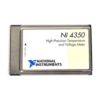
About the NI 4350 Instruments Thank you for buying a National Instruments 4350 instrument. The NI 4350 family consists of three instruments for the bus of your choice: PCMCIA, ISA, and Universal Serial Bus (USB). The NI 4350 instruments feature accurate thermocouple and DC voltage measurements. -
Page 12: What You Need To Get Started
Detailed specifications for the NI 4350 instruments are in Appendix A, Specifications. What You Need to Get Started To set up and use your NI 4350 instrument, you will need the following: One of the following NI 4350 instruments: – NI 4350 (PCMCIA) –... -
Page 13: Unpacking
NI 4350 (PCMCIA) Your NI 4350 (PCMCIA) is shipped in an antistatic vinyl case; when you are not using your NI 4350 (PCMCIA), store it in this case. Because your NI 4350 (PCMCIA) is enclosed in a fully shielded case, no additional electrostatic precautions are necessary. -
Page 14: Software Programming Choices
NI-DAQ software kit. The LabWindows/CVI Data Acquisition library is functionally equivalent to the NI-DAQ software. NI 4350 instruments are supported by the Easy I/O for DAQ library in LabWindows/CVI. Use of the NI435X instrument driver is recommended while using LabWindows/CVI. -
Page 15: Ni435X Instrument Driver And Ni-Daq
Introduction data storage by adding timestamps, measurements, user name, and comments. Your NI 4350 works with VirtualBench-Logger and VirtualBench-DIO. VirtualBench-Logger is a turn-key application that allows you to make measurements as you would with a standard bench-type data logger. VirtualBench-DIO allows you to read from or write to the digital I/O lines. -
Page 16: Optional Equipment
NI 4350 Figure 1-1. The Relationship between the Programming Environment, NI-DAQ and Your Hardware Optional Equipment National Instruments offers a variety of products to use with your NI 4350, including cables, connector blocks, terminal blocks and other accessories, as follows: •... -
Page 17: Software Installation
Hardware Installation ♦ NI 4350 (PCMCIA) You can install the NI 4350 (PCMCIA) in any available Type II PCMCIA slot in your computer. Windows 95 or higher includes the Plug and Play services your operating system will use. Windows NT 4.0 or higher includes the drivers needed to use PCMCIA cards. - Page 18 ♦ NI 4350 (ISA) You can install the NI 4350 (ISA) in any available ISA, AT, or XT slot in your computer. However, for best noise performance, leave as much room as possible between the NI 4350 (ISA) and other hardware.
- Page 19 If the LED comes on after the NI 4350 (USB) is connected to the host, it is functioning properly. If the LED remains off or blinks, refer to Table 2-1.
-
Page 20: Configuration
Chapter 2 Installation and Configuration Table 2-1. LED Patterns for the NI 4350 (USB) States NI 4350 (USB) State Description Configured state Your NI 4350 (USB) is configured. Off or in the low-power, Your NI 4350 (USB) is turned suspend mode off or in the low-power, suspend mode. -
Page 21: Power Considerations For The Ni 4350 (Usb)
USB cable. There are circumstances when the NI 4350 (USB) may require more power than the USB power supply can safely deliver, so if the NI 4350 (USB) tries to draw more than the allowed current from the USB power supply, internal protection circuitry will turn off most of the circuitry in the NI 4350 (USB) to protect the USB supply. -
Page 22: Describes How To Use Your Ni
Chapter NI 4350 Operation This chapter describes how to use your NI 4350 instrument and includes operation tips on taking measurements with temperature sensors such as thermocouples, RTDs, and thermistors, as well as measuring voltages and resistances. Warming up Your NI 4350 Instrument... -
Page 23: Choosing A Reading Rate
Choosing a Reading Rate The reading rate is the rate at which your NI 4350 takes a new measurement. This rate has a direct relationship with the digital filter built into the ADC used in the NI 4350. - Page 24 10, 50, 60, 1.4‡ and 400 fast 50 and 400 2.1‡ fast 2.1‡ *Number of power-line cycles used for filtering †Power line frequency ‡For resistance ranges of 50 kΩ and higher © National Instruments Corporation NI 4350 User Manual...
-
Page 25: Knowing Your Signal Source
A ground-referenced signal source is one that is connected in some way to the building system ground and is, therefore, already connected to a common ground point with respect to the NI 4350 instrument, assuming that the computer is plugged into the same power system. Examples of... -
Page 26: Using Programmable Open-Thermocouple Detection
The default setting for programmable ground referencing is on in volts measurement mode and off in 4-wire ohms mode. Using Programmable Open-Thermocouple Detection The NI 4350 instruments have software-programmable, open-thermocouple detection on every channel, which you can use to detect an open or broken thermocouple. This feature connects CH+ to +2.5 V through a 10 MΩ... -
Page 27: Measuring Temperature With Thermocouples
EMF. However, just measuring this voltage is not sufficient because connecting the thermocouple to the NI 4350 instrument accessory creates the reference junction or cold-junction, shown in Figure 3-2. These additional junctions act as thermocouples, themselves, and produce their own voltages. -
Page 28: Figure 3-2. Effect Of The Cold-Junction
With the NI 4350 instruments, you can perform cold-junction compensation in software. To do this, you can use the thermistor temperature sensor on the NI 4350 accessory to measure the ambient temperature at the cold-junction and compute the appropriate compensation for the unwanted thermoelectric voltages using software. -
Page 29: Connecting Your Thermocouple
The NI 4350 accessories—the PSH32-TC6 and the CB-27T for the NI 4350 (PCMCIA), and the TC-2190 and the TBX-68T for the NI 4350 (ISA) and the NI 4350 (USB)—are designed to be used with thermocouples. Consult your accessory installation guide for instructions on how to connect your thermocouples. -
Page 30: Auto-Zero
If you determine that your thermocouple is floating, switch on ground-referencing on that channel. Otherwise, the thermocouple inputs may float out of the input common-mode limits of the NI 4350 instrument. When you use the PSH32-TC6, CB-27T, TC-2190, and TBX-68T accessories, always switch on ground-referencing on CH1. -
Page 31: Programmable Open-Thermocouple Detection
Alternatively, you can switch off the open-thermocouple detection to eliminate the current injected into the thermocouple. AC Noise Effects Your NI 4350 instrument rejects AC voltages as specified in NMR in Appendix A, Specifications. However, if the amplitudes of the AC... -
Page 32: Measuring Dc Voltage
Your NI 4350 instrument has six bipolar input ranges available for measuring DC voltage. These ranges are ±625 mV, ±1.25 V, ±2.5 V, ±3.75 V, ±7.5 V, and ±15 V. The NI 4350 instrument can measure DC voltage to the specified accuracy as long as the voltage is within the selected input range. -
Page 33: Optimizing Measurements
You can measure the voltage offset on this auto-zero channel and subtract it from the voltage measurements on other channels. This way, you can compensate for any residual offset error the NI 4350 instrument may have. This is especially useful when the NI 4350 instrument is operating at an ambient temperature other than that of calibration (23°... -
Page 34: Programmable Open-Thermocouple Detection
25 kΩ, you should measure the same channel for up to 1 s, then switch to another channel to achieve the specified accuracy. AC Noise Effects Your NI 4350 instrument rejects AC voltages as specified in NMR in Appendix A, Specifications. However, if the amplitudes of the AC... -
Page 35: Measuring Temperature With Rtds And Thermistors And Measuring Resistance
With the NI 4350, you can excite your resistor with the built-in precision current source and measure the resulting voltage. When using LabVIEW, set the measurements mode to 4-wire ohms.When using the... - Page 36 RTD in Ω at 0° C, A, B, and C are the Callendar-Van Dusen coefficients shown in Table 3-4, and T is the temperature in ° C. For temperatures above 0° C, coefficient C equals 0. © National Instruments Corporation 3-15 NI 4350 User Manual...
-
Page 37: Connecting Your Rtd
RTD will add errors to your readings. For example, consider a two-wire RTD element connected to the NI 4350 instrument accessory that also supplies a constant current source IEX to excite the RTD. As shown in... -
Page 38: Figure 3-4. Two-Wire Rtd Measurement
RTD in a Wheatstone configuration with a current source. Another variation of the three-wire RTD configuration is shown in Figure 3-7. In this configuration, the resistance R of only one lead adds error to the measurement. © National Instruments Corporation 3-17 NI 4350 User Manual... -
Page 39: Introduction To Thermistors
(NTC) thermistors and positive temperature coefficient (PTC) thermistors. An NTC thermistor is one whose resistance decreases with increasing temperature. A PTC thermistor is one whose resistance increases with increasing temperature. NTC thermistors are much more NI 4350 User Manual 3-18 © National Instruments Corporation... -
Page 40: Figure 3-8. Resistance-Temperature Curve Of A Thermistor
5,000 Ω thermistor. The curve of a 100 Ω RTD is also shown for comparison. 10 M Thermistor (5,000 Ω at 25˚ C) 100 k 10 k (PT 100 Ω at 0˚ C) Temperature (˚C) Figure 3-8. Resistance-Temperature Curve of a Thermistor © National Instruments Corporation 3-19 NI 4350 User Manual... -
Page 41: Resistance-Temperature Characteristic Of Thermistors
Because the thermistor is a resistive device, you must pass a current through the thermistor to produce a voltage that can be measured by the NI 4350 instrument. The high resistance and high sensitivity of the thermistor simplify the necessary measurement circuitry and signal conditioning. -
Page 42: Connecting Your Resistor
The NI 4350 accessories—the CB-27T and CB-27 for the NI 4350 (PCMCIA), and the TBX-68T and TBX-68 for the NI 4350 (ISA) and the NI 4350 (USB)—are designed to be used with RTDs, thermistors, and resistors. Consult your accessory installation guide for instructions on how to connect your resistors. - Page 43 To prevent possible safety hazards, the maximum voltage between any of the analog inputs and the computer ground should never exceed ±42 VDC when the NI 4350 instrument is powered up and ±17 VDC when the NI 4350 instrument is powered down.
-
Page 44: Input Ranges
NI 4350 Operation Input Ranges The NI 4350 has six ranges for resistance measurements. These ranges are 25 kΩ, 50 kΩ, 100 kΩ, 150 kΩ, 300 kΩ, and 600 kΩ.These ranges correspond to the six input ranges available for measuring DC voltages developed across resistors. -
Page 45: Programmable Ground-Referencing
Chapter 3 NI 4350 Operation especially useful when your NI 4350 instrument is operating at an ambient temperature other than that of calibration (23° C typical). Use the 4-wire mode in LabVIEW while reading the offset for resistance measurements. Note: When using VirtualBench-Logger along with NI 4350 accessories—... -
Page 46: Self-Heating
R > 10 kΩ Four-wire, three-wire, or two-wire Self-Heating The current source on the NI 4350 instrument is designed such that any error resulting from self-heating is negligible in most cases. This section explains how that occurs. When current is passed through an RTD or a thermistor (both are... -
Page 47: Ac Noise Effects
However, if the amplitudes of the AC noise are large compared to the DC signal, or if the peak value (AC + DC) of the measured signal is outside the input range, the NI 4350 instrument may exhibit additional errors. To minimize these errors,... -
Page 48: Using Digital Inputs And Outputs
Connecting Your Digital Input and Output All NI 4350 accessories are designed to be used for DIO. Refer to your accessory installation guide for instructions on how to connect your DIO lines. -
Page 49: Figure 3-11. Examples Of Dio Applications
DGND Figure 3-11. Examples of DIO Applications The DIO lines of the NI 4350 instrument are protected against damage from voltages within – 0.5 and +5.5 V with respect to digital ground (DGND). You should never apply voltages above these levels to these signals. -
Page 50: Table 3-6. Logic Family Thresholds*
Table 3-6. Logic Family Thresholds* Logic Family High CMOS < 0.8 V > 2.0 V < 0.8 V > 2.0 V * Check your logic family data sheets for any variations. © National Instruments Corporation 3-29 NI 4350 User Manual... -
Page 51: Lists The Specifications Of The Ni
Appendix Specifications This appendix lists the specifications of the NI 4350. These specifications are for 15° to 35° C ambient temperature range for one year unless otherwise specified. All specifications are relative to calibration standards and require a 30 minute warm-up period. - Page 52 1.14 1.69 1820 0.74 1.05 1.50 ° ° † Add when thermocouple accessory and NI 4350 is outside 15 –35 C temperature range ° ° * Add when thermocouple accessory is outside 15 –35 C temperature range NI 4350 User Manual...
- Page 53 Thermistor accuracy is valid for all filter settings. Specifications assume that the 25 kΩ range is used and worst case common mode voltage for this range is present. Specifications improve is actual common mode voltage is less than worst case. © National Instruments Corporation NI 4350 User Manual...
- Page 54 Resistance specifications assume worst case common mode voltage for the given range. Specifications improve if actual common mode voltage is less than worst case. Measurement accuracy is affected by source impedance. Resistances > 25 kΩ may require 1 s setting time. NI 4350 User Manual © National Instruments Corporation...
- Page 55 10 Hz: accuracy is 0.42° C [directly from table] • Measurement of 760° C using J type thermocouple with NI 4350 at 38° C and accessory (cold-junction sensor) at 23° C; filter setting of 10 Hz: accuracy is 0.48°...
- Page 56 Data transfers ........Interrupts, programmed I/O Warm-up time ........30 minutes Amplifier Characteristics Input impedance Normal powered on ..... >1 GΩ in parallel with 0.39 µF Powered off ......... 10 kΩ Overload........10 kΩ NI 4350 User Manual © National Instruments Corporation...
- Page 57 Bandwidth ..........20 Hz Step response (full-scale step Accuracy Time (s) ±0.1% ±0.01% ±0.0015% ±0.001% ±0.0004% Excitation Number of channels ......1 Level ..........25 µA Maximum load resistance ....600 kΩ Temperature coefficient ......±15 ppm/° C © National Instruments Corporation NI 4350 User Manual...
- Page 58 Bus Interface Type ........... Slave (Plug and Play) Power Requirement PCMCIA ..........130 mA at +5 V ISA............. 160 mA at +5 V USB ........... High power, USB powered peripheral (500 mA) NI 4350 User Manual © National Instruments Corporation...
- Page 59 (5.8 by 8.4 by 1.5 in.) I/O connector PCMCIA ........32-pin female, shielded and latched ISA and USB........68-pin male, shielded and latched Environment Operating temperature ......0° to 55° C Storage temperature ......–20° to 70° C © National Instruments Corporation NI 4350 User Manual...
- Page 60 ♦ The NI 4350 (PCMCIA) kit includes a label that you should apply to your CB-27 accessory. This label provides the pin correlation between these two devices. The following table shows how the screw terminals on the CB-27 correspond to the signal names on the NI 4350 (PCMCIA).
- Page 61 NI 4350 (PCMCIA) Table B-1. Using the with the CB-27 (Continued) NI 4350 (PCMCIA) CB-27 Screw Signal Name Terminal CH6– CH7+ CH7– AGND IEX+ IEX– RSVD1 RSVD2 DIO0 DIO1 DIO2 DIO3 DGND © National Instruments Corporation NI 4350 User Manual...
- Page 62 ♦ The NI 4350 (ISA and USB) accessories—TBX-68, SH6868, and R6868— have a one-to-one correlation to pins on the NI 4350 (ISA). Table B-2. Using the NI 4350 (ISA and USB) with the TBX-68 NI 4350 (ISA and USB) TBX-68...
- Page 63 Appendix B Signal Connections Table B-2. Using the NI 4350 (ISA and USB) with the TBX-68 (Continued) NI 4350 (ISA and USB) TBX-68 Signal Name Screw Terminal CH9– CH10+ CH10– CH11+ CH11– CH12+ CH12– CH13+ CH13– CH14+ CH14– CH15+ CH15–...
- Page 64 9, 10, 11, 14, 16, 20, 24, 27, 32, 43, 44, 47, 48, 51, 56, 59, 64, 67 * The current available may be limited to less than 50 mA (typical) when using the NI 4350 (USB). © National Instruments Corporation...
- Page 65 Electronic Services Bulletin Board Support National Instruments has BBS and FTP sites dedicated for 24-hour support with a collection of files and documents to answer most common customer questions. From these sites, you can also download the latest instrument drivers, updates, and example programs. For recorded instructions on how to use the bulletin board and FTP services and for BBS automated information, call 512 795 6990.
- Page 66 Telephone and Fax Support National Instruments has branch offices all over the world. Use the list below to find the technical support number for your country. If there is no National Instruments office in your country, contact the source from which you purchased your software to obtain support.
- Page 67 National Instruments for technical support helps our applications engineers answer your questions more efficiently. If you are using any National Instruments hardware or software products related to this problem, include the configuration forms from their user manuals. Include additional pages if necessary.
- Page 68 Complete a new copy of this form each time you revise your software or hardware configuration, and use this form as a reference for your current configuration. Completing this form accurately before contacting National Instruments for technical support helps our applications engineers answer your questions more efficiently.
- Page 69 Documentation Comment Form National Instruments encourages you to comment on the documentation supplied with our products. This information helps us provide quality products to meet your needs. Title: NI 4350 User Manual Edition Date: May 1998 Part Number: 321566B-01 Please comment on the completeness, clarity, and organization of the manual.
- Page 70 – 6 µ- micro- –3 milli- kilo- mega- giga- Numbers/Symbols percent positive of, or plus – negative of, or minus ± plus or minus ° degree Ω +5 V output signal © National Instruments Corporation NI 4350 User Manual...
- Page 71 Typically, a bus is the expansion vehicle to which I/O or other instruments are connected. Examples of PC buses are the AT bus (also known as the ISA bus) and the PCI bus. NI 4350 User Manual © National Instruments Corporation...
- Page 72 Plug-in boards, PCMCIA cards, and instruments such as the NI 4350 (USB), which connects to your computer USB port, are all examples of DAQ devices.
- Page 73 NI 4350 User Manual © National Instruments Corporation...
- Page 74 (2) mega, the prefix for 1,048,576, or 2 , when used with B to quantify data or computer memory megabytes of memory Mbytes/s a unit for data transfer that means 2 or 1,048,576 bytes/s © National Instruments Corporation NI 4350 User Manual...
- Page 75 Glossary NI-DAQ National Instruments driver software for DAQ hardware, including computer-based instruments NIST National Institute of Standards and Technology normal mode rejection noise an undesirable signal—Electrical Noise comes from external sources such as the AC power line, motors, generators, transformers,...
- Page 76 A metallic probe that measures temperature based upon its resistance. second—a unit of time sample samples per second—used to express the rate at which a NI 4350 samples an analog signal sigma-delta technology used for analog to digital conversion...
- Page 77 (2) a LabVIEW software module (VI), which consists of a front panel user interface and a block diagram program VirtualBench software suite of stand-alone virtual instruments that combine DAQ products, software, and PCs NI 4350 User Manual © National Instruments Corporation...
- Page 78 EMF, 3-13 auto-zero optimization digital inputs and outputs, 3-27 to 3-29 DC voltage measurement, 3-9 connecting, 3-27 to 3-29 RTDs, thermistors, and resistors, DIO application examples (figure), 3-28 3-23 to 3-24 thermocouples, 3-9 © National Instruments Corporation NI 4350 User Manual...
- Page 79 3-1 ground-referenced signal source, 3-4 ground-referencing, programmable optimizing measurements National Instruments application software, 1-4 DC voltage measurement, 3-12 NI 4350 instruments. See also operation of RTDs, thermistors, and resistors, NI 4350 instruments. 3-23 to 3-24 configuration, 2-4 thermocouples, 3-9...
- Page 80 3-8 thermocouples, 3-10 optimizing measurements, settings (table), 3-6 3-8 to 3-11 operation of NI 4350 instruments, 3-1 to 3-29 warming up NI 4350 instrument, 3-1 current source, 3-26 optimizing measurements DC voltage measurement, 3-11 to 3-13 DC voltage, 3-12 to 3-13...
- Page 81 3-25 to 3-26 thermal EMF, 3-26 two-wire, three-wire, and four-wire physical specifications, A-9 measurements, 3-24 to 3-25 power considerations, for NI 4350 (USB), 2-5 RTDs, 3-14 to 3-18 power requirements, A-8 connecting, 3-16 to 3-18 programmable ground-referencing. See relationship of resistance and ground-referencing, programmable.
- Page 82 3-25 to 3-26 technical support, C-1 to C-2 signal connections, B-1 to B-5 telephone and fax support numbers, C-2 using NI 4350 (ISA and USB) with temperature measurement TBX-68 (table), B-3 to B-5 RTDs, 3-14 to 3-18...
- Page 83 3-1 3-6 to 3-11 range selection, 3-1 accuracy specifications (table), A-1 to A-2 cold-junction compensation options, 3-7 to 3-8 warming up NI 4350 instrument, 3-1 cold-junction effect (figure), 3-7 connecting thermocouple, 3-8 NI 4350 User Manual © National Instruments Corporation...
Need help?
Do you have a question about the NI 4350 and is the answer not in the manual?
Questions and answers